key YAMAHA XMAX 125 2018 Owner's Manual
[x] Cancel search | Manufacturer: YAMAHA, Model Year: 2018, Model line: XMAX 125, Model: YAMAHA XMAX 125 2018Pages: 114, PDF Size: 8.24 MB
Page 63 of 114

Operation and important riding points
6-6
6
EAUN1421
Parking
When parking, turn the vehicle power
off, and then turn the smart key off.
TIP
Even when the vehicle is parked in a lo-
cation partitioned by a fence or the
glass window of a shop, if the smart
key is within operating range, other
people will be able to start the engine
and operate the vehicle. Please turn
the smart key off when leaving the ve-
hicle. (See page 3-5.)
If the sidestand is lowered when the
engine is running, the engine will stop
and the beeper will sound for approxi-
mately 1 minute. To stop the beeper,
turn the vehicle power off or raise the
sidestand.
TIP
Before leaving the vehicle, be sure
to turn the main switch to “OFF”
or “ ”. Otherwise, the battery may
discharge.
The sidestand alarm beeper can
be set to not activate. Please con-
tact your Yamaha dealer.
WARNING
EWA10312
Since the engine and exhaust
system can become very hot,
park in a place where pedestri-
ans or children are not likely to
touch them and be burned.
Do not park on a slope or on soft
ground, otherwise the vehicle
may overturn, increasing the
risk of a fuel leak and fire.Do not park near grass or other
flammable materials which
might catch fire.
UBL2E0E0.book Page 6 Friday, June 23, 2017 9:30 AM
Page 95 of 114

Periodic maintenance and adjustment
7-32
7
EAU60701
Troubleshooting
Although Yamaha vehicles receive a
thorough inspection before shipment
from the factory, trouble may occur
during operation. Any problem in the
fuel, compression, or ignition systems,
for example, can cause poor starting
and loss of power.
The following troubleshooting charts
represent quick and easy procedures
for checking these vital systems your-
self. However, should your vehicle re-
quire any repair, take it to a Yamaha
dealer, whose skilled technicians have
the necessary tools, experience, and
know-how to service the vehicle prop-
erly.
Use only genuine Yamaha replace-
ment parts. Imitation parts may look
like Yamaha parts, but they are often
inferior, have a shorter service life and
can lead to expensive repair bills.
WARNING
EWA15142
When checking the fuel system, do
not smoke, and make sure there are
no open flames or sparks in the ar-
ea, including pilot lights from water
heaters or furnaces. Gasoline or
gasoline vapors can ignite or ex-
plode, causing severe injury or prop-
erty damage.
EAU76551Smart key system troubleshooting
Please check the following items when
the smart key system does not work.
Is the smart key turned on? (See
page 3-5.)
Is the smart key battery dis-
charged? (See page 3-6.)Is the smart key battery installed
correctly? (See page 3-6.)
Is the smart key being used in a lo-
cation with strong radio waves or
other electromagnetic noise? (See
page 3-1.)
Are you using the smart key that is
registered to the vehicle?
Is the vehicle battery discharged?
When the vehicle battery is dis-
charged, the smart key system will
not operate. Please have the vehi-
cle battery charged or replaced.
(See page 7-26.)
If the smart key system does not work
after checking the above items, have a
Yamaha dealer check the smart key
system.
TIP
See Emergency mode on page 7-35
for information on starting the engine
without the smart key.
UBL2E0E0.book Page 32 Friday, June 23, 2017 9:30 AM
Page 98 of 114

Periodic maintenance and adjustment
7-35
7
EAU76561
Emergency mode
When the smart key is lost or dam-
aged, or its battery has discharged, the
vehicle can still be turned on and the
engine started. You will need the smart
key system identification number.
To operate the vehicle in emergency
mode
1. Stop the vehicle in a safe place
and turn the main switch to “OFF”.
2. Push the main switch knob for 5
seconds until the smart key sys-
tem indicator light flashes once,
then release it. Repeat two more
times. The smart key system indi-
cator light will come on for three
seconds to indicate the transition
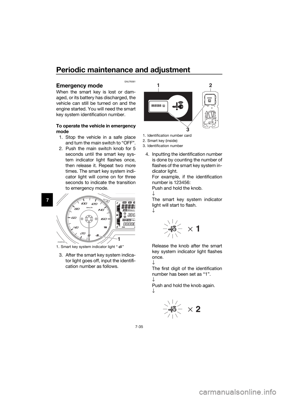
to emergency mode.
3. After the smart key system indica-
tor light goes off, input the identifi-
cation number as follows.4. Inputting the identification number
is done by counting the number of
flashes of the smart key system in-
dicator light.
For example, if the identification
number is 123456:
Push and hold the knob.
↓
The smart key system indicator
light will start to flash.
↓
Release the knob after the smart
key system indicator light flashes
once.
↓
The first digit of the identification
number has been set as “1”.
↓
Push and hold the knob again.
↓
1. Smart key system indicator light “ ”
ZAUM15301
1. Identification number card
2. Smart key (inside)
3. Identification number
868588
868588
1
32
UBL2E0E0.book Page 35 Friday, June 23, 2017 9:30 AM
Page 99 of 114

Periodic maintenance and adjustment
7-36
7 Release the knob after the smart
key system indicator light flashes
twice.
↓
The second digit has been set as
“2”.
↓
Repeat the above procedure until
all digits of the identification num-
ber have been set. The smart key
system indicator light will flash for
10 seconds if the correct identifi-
cation number was entered.
TIP
When one of the following situations
applies, emergency mode will be ter-
minated and the smart key system in-
dicator light will flash quickly for 3
seconds. In this case, start over again
from step 2.
When there are no knob opera-
tions for 10 seconds during the
identification number input pro-
cess.
When the smart key system indi-
cator light is allowed to flash nine
or more times.
The identification number is not
entered correctly.
5. While the smart key system indi-
cator light is on, push the knob
once more to complete emergen-
cy mode access. The smart key
indicator light will go off and then
come back on for approximately 4
seconds.
6. While the smart key system indi-
cator light is on, turn the main
switch to “ON”. The vehicle can
now be operated normally.
UBL2E0E0.book Page 36 Friday, June 23, 2017 9:30 AM
Page 107 of 114

Specifications
9-3
9
High beam indicator light:
LED
Turn signal indicator light:
LED
Engine trouble warning light:
LED
ABS warning light:
LED
Smart key system indicator light:
LED
Traction control system indicator/warning
light:
LED
Fuse(s):
Main fuse:
20.0 A
Main fuse 2:
7.5 A
Terminal fuse 1:
2.0 A
Signaling system fuse:
10.0 A
Signaling system fuse 2:
7.5 A
Radiator fan motor fuse:
7.5 A
Turn signal light and hazard fuse:
7.5 A
ABS control unit fuse:
7.5 A
ABS motor fuse:
30.0 A
ABS solenoid fuse:
15.0 A
Answer back fuse:
2.0 A
Backup fuse:
7.5 A
UBL2E0E0.book Page 3 Friday, June 23, 2017 9:30 AM
Page 110 of 114

11-1
11
Index
A
ABS ....................................................... 4-14
ABS warning light ................................... 4-1
Acceleration and deceleration ................ 6-3
Air filter and V-belt case air filter
elements ............................................. 7-14
Auxiliary DC jack ................................... 4-29
Auxiliary lights ....................................... 7-29
B
Battery .................................................. 7-26
Brake fluid, changing ............................ 7-21
Brake fluid level, checking .................... 7-20
Brake lever, front .................................. 4-13
Brake lever, rear.................................... 4-14
Brake levers, lubricating ....................... 7-23
Brake/tail light ....................................... 7-30
Braking.................................................... 6-4
C
Cables, checking and lubricating ......... 7-22
Care ........................................................ 8-1
Catalytic converters .............................. 4-20
Centerstand and sidestand, checking
and lubricating .................................... 7-24
Coolant ................................................. 7-12
D
Data recording, vehicle ......................... 10-2
Diagnostic connectors .......................... 10-2
Dimmer/Pass switch ............................. 4-12
E
Emergency mode.................................. 7-35
Engine break-in....................................... 6-5
Engine oil ................................................ 7-9
Engine serial number ............................ 10-1
Engine trouble warning light ................... 4-1
F
Final transmission oil ............................ 7-11
Front and rear brake lever free play,
checking ............................................. 7-19
Front and rear brake pads, checking.... 7-20
Front fork, checking .............................. 7-24
Front turn signal light ............................ 7-30
Fuel ....................................................... 4-18
Fuel consumption, tips for reducing ....... 6-5
Fuel tank cap ........................................ 4-17
Fuel tank overflow hose ........................ 4-19
Fuses, replacing.................................... 7-27
H
Handlebar position, adjusting ............... 4-25
Handlebar switches .............................. 4-12
Hazard switch ....................................... 4-12Headlights ............................................ 7-29
High beam indicator light ....................... 4-1
Horn switch .......................................... 4-12
I
Identification numbers .......................... 10-1
Ignition circuit cut-off system............... 4-27
Indicator lights and warning lights ......... 4-1
K
Key, handling of smart and mechanical
keys ...................................................... 3-3
L
License plate light bulb, replacing........ 7-31
M
Main switch ............................................ 3-8
Maintenance and lubrication, periodic ... 7-4
Maintenance, emission control
system.................................................. 7-3
Matte color, caution ............................... 8-1
Model label ........................................... 10-1
Multi-function display ............................. 4-3
O
Operating range of the smart key
system.................................................. 3-2
P
Panel, removing and installing ............... 7-7
Parking ................................................... 6-6
Part locations ......................................... 2-1
S
Safe-riding points ................................... 1-5
Safety information .................................. 1-1
Shock absorber assemblies,
adjusting............................................. 4-25
Sidestand ............................................. 4-26
Smart key ............................................... 3-5
Smart key battery, replacing .................. 3-6
Smart key system ................................... 3-1
Smart key system indicator light ............ 4-2
Smart key system, troubleshooting...... 7-32
Spark plug, checking ............................. 7-8
Specifications ......................................... 9-1
Speedometer .......................................... 4-2
Starting off.............................................. 6-3
Starting the engine ................................. 6-2
Steering, checking................................ 7-25
Stop/Run/Start switch .......................... 4-12
Storage ................................................... 8-4
Storage compartments ........................ 4-20
T
Tachometer ............................................ 4-3
UBL2E0E0.book Page 1 Friday, June 23, 2017 9:30 AM