engine overheat YAMAHA XMAX 125 2021 Owners Manual
[x] Cancel search | Manufacturer: YAMAHA, Model Year: 2021, Model line: XMAX 125, Model: YAMAHA XMAX 125 2021Pages: 114, PDF Size: 13.55 MB
Page 36 of 114

Instrument and control functions
5-5
5 5. Push the ŌĆ£TRIPŌĆØ switch for three
seconds, and then release it. The
minute digits will start flashing.
6. Use the ŌĆ£TRIPŌĆØ switch to set the minutes.
7. Push the ŌĆ£TRIPŌĆØ switch for three seconds, and then release it to
start the clock.
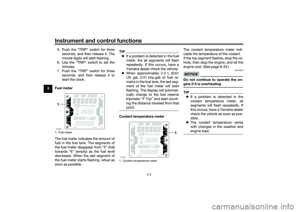
Fuel meter
The fuel meter indicates the amount of
fuel in the fuel tank. The segments of
the fuel meter disappear from ŌĆ£FŌĆØ (full)
towards ŌĆ£EŌĆØ (empty) as the fuel level
decreases. When the last segment of
the fuel meter starts flashing, refuel as
soon as possible.
TIP’ü¼ If a problem is detected in the fuel
meter, the all segments will flash
repeatedly. If this occurs, have a
Yamaha dealer check the vehicle.
’ü¼ When approximately 2.3 L (0.61
US gal, 0.51 Imp.gal) of fuel re-
mains in the fuel tank, the last seg-
ment of the fuel meter will start
flashing. The display will automat-
ically change to the fuel reserve
tripmeter ŌĆ£F TripŌĆØ and start count-
ing the distance traveled from that
point.Coolant temperature meter The coolant temperature meter indi-
cates the temperature of the coolant.
If the top segment flashes, stop the ve-
hicle, then stop the engine, and let the
engine cool. (See page 8-33.)
NOTICE
ECA10022
Do not continue to operate the en-
g
ine if it is overheatin g.TIP’ü¼ If a problem is detected in the
coolant temperature meter, all
segments will flash repeatedly. If
this occurs, have a Yamaha dealer
check the vehicle as soon as pos-
sible.
’ü¼ The coolant temperature varies
with changes in the weather and
engine load.
1. Fuel meterZAUM14831
1. Coolant temperature meterZAUM1484
1
UB9YE0E0.book Page 5 Wednesday, January 6, 2021 3:03 PM
Page 62 of 114

Operation and important rid ing points
7-1
7
EAU15952
Read the OwnerŌĆÖs Manual carefully to
become familiar with all controls. If
there is a control or function you do not
understand, ask your Yamaha dealer.
WARNING
EWA10272
Failure to familiarize yourself with
the controls can lead to loss of con-
trol, which coul d cause an acci dent
or injury.
EAU16831
En gine break-inThere is never a more important period
in the life of your engine than the period
between 0 and 1000 km (600 mi). For
this reason, you should read the fol-
lowing material carefully.
Since the engine is brand new, do not
put an excessive load on it for the first
1000 km (600 mi). The various parts in
the engine wear and polish themselves
to the correct operating clearances.
During this period, prolonged full-throt-
tle operation or any condition that
might result in engine overheating
must be avoided.
EAUM4310
0ŌĆō500 km (0ŌĆō300 mi)
Avoid prolonged operation above 5000
r/min.
500ŌĆō1000 km (300ŌĆō600 mi)
Avoid prolonged operation above 6000
r/min. NOTICE: After 1000 km (600
mi) of operation, be sure to replace
the en gine oil an d clean the oil
strainer, an d replace the final trans-
mission oil.
[ECA23650]
1000 km (600 mi) an d b eyon d
The vehicle can now be operated nor-
mally.NOTICE
ECA10311
’ü¼ Keep the en gine spee d out of
the tachometer red zone.
’ü¼ If any en gine trou ble shoul d oc-
cur during the en gine break-in
period , imme diately have a
Yamaha dealer check the vehi-
cle.
UB9YE0E0.book Page 1 Wednesday, January 6, 2021 3:03 PM
Page 99 of 114

Periodic maintenance an d a djustment
8-33
8
EAU86420
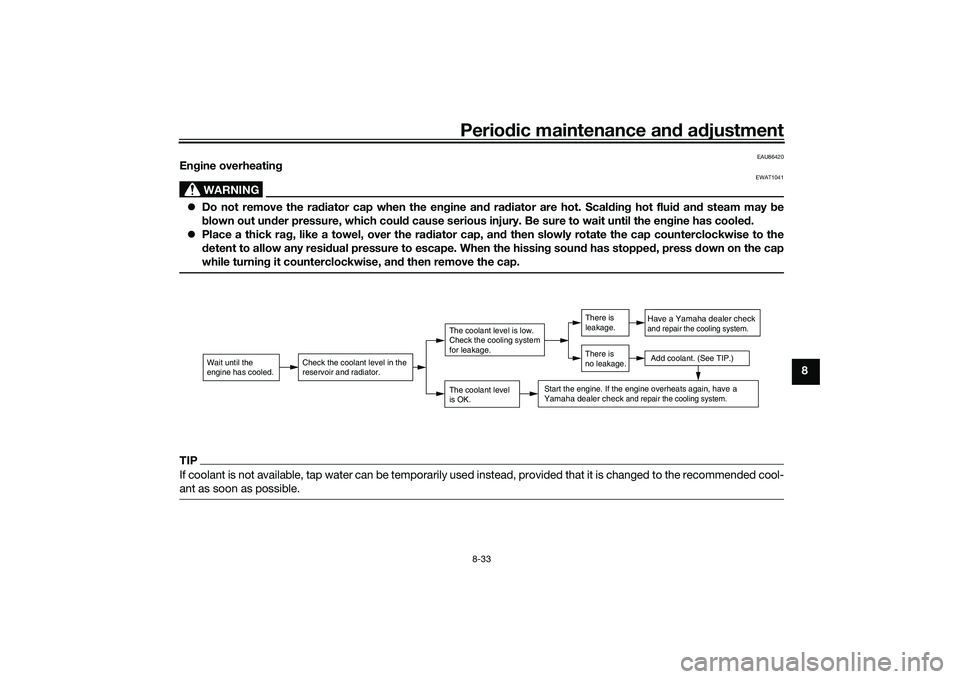
En gine overheatin g
WARNING
EWAT1041
’ü¼Do not remove the ra diator cap when the en gine an d ra diator are hot. Scal din g hot flui d an d steam may be
b lown out un der pressure, which coul d cause serious injury. Be sure to wait until the en gine has coole d.
’ü¼ Place a thick ra g, like a towel, over the ra diator cap, an d then slowly rotate the cap counterclockwise to the
d etent to allow any resi dual pressure to escape. When the hissin g soun d has stoppe d, press down on the cap
while turnin g it counterclockwise, an d then remove the cap.TIPIf coolant is not available, tap water can be temporarily used instead, provided that it is changed to the recommended cool-
ant as soon as possible.
Wait until the
engine has cooled.
Check the coolant level in the
reservoir and radiator.
The coolant level
is OK.The coolant level is low.
Check the cooling system
for leakage.
Have a Yamaha dealer checkand repair the cooling system.Add coolant. (See TIP.)
Start the engine. If the engine overheats again,
have a
Yamaha dealer check
and repair the cooling system.
There is
leakage.
There is
no leakage.
UB9YE0E0.book Page 33 Wednesday, January 6, 2021 3:03 PM
Page 111 of 114

12-1
12
Index
AABS warning light ................................... 5-2
Acceleration and deceleration ................ 7-3
Activating the Stop and Start System .... 4-1
Air filter and V-belt case air filter
elements ............................................. 8-14
Anti-lock brake system (ABS)............... 5-14
Auxiliary DC jack .................................. 5-26BBattery .................................................. 8-26
Brake fluid, changing............................ 8-22
Brake fluid level, checking.................... 8-21
Brake lever, front .................................. 5-14
Brake lever, rear ................................... 5-14
Brake levers, lubricating ....................... 8-23
Braking ................................................... 7-3CCables, checking and lubricating ......... 8-23
Canister ................................................ 8-10
Care ........................................................ 9-1
Catalytic converter ............................... 5-20
Centerstand and sidestand, checking and lubricating ................................... 8-24
Coolant ................................................. 8-13DData recording, vehicle......................... 11-2
Diagnostic connector ........................... 11-2
Dimmer/Pass switch............................. 5-12EEmergency mode ................................. 8-34
Engine break-in ...................................... 7-1
Engine oil and oil strainer ..................... 8-10
Engine overheating ............................... 8-33
Engine serial number ............................ 11-1
FFinal transmission oil............................ 8-12
Front and rear brake lever free play, checking ............................................ 8-19
Front and rear brake pads, checking ... 8-20
Front fork, checking ............................. 8-25
Front turn signal light ........................... 8-29
Fuel ...................................................... 5-18
Fuel consumption, tips for reducing ...... 7-4
Fuel tank cap........................................ 5-17
Fuel tank overflow hose ....................... 5-20
Fuses, replacing ................................... 8-27HHandlebar position, adjusting .............. 5-25
Handlebar switches ............................. 5-12
Hazard switch ...................................... 5-13
High beam indicator light ....................... 5-1
Horn switch .......................................... 5-13IIdentification numbers ......................... 11-1
Ignition circuit cut-off system .............. 5-27
Indicator lights and warning lights ......... 5-1KKey, handling of smart and mechanical keys...................................................... 3-3LLicense plate light bulb, replacing ....... 8-30MMain switch ............................................ 3-8
Maintenance and lubrication, periodic... 8-4
Maintenance, emission control system ................................................. 8-3
Malfunction indicator light (MIL)............. 5-1
Matte color, caution ............................... 9-1 Model label ........................................... 11-1
Multi-function display ............................. 5-4
OOperating range of the smart key
system .................................................. 3-2PPanel, removing and installing ................ 8-8
Parking.................................................... 7-4
Part locations.......................................... 2-1
Precautions when using the Stop and Start System ......................................... 4-3SSafe-riding points ................................... 1-5
Safety information................................... 1-1
Shock absorber assemblies, adjusting ............................................. 5-25
Sidestand.............................................. 5-27
Smart key................................................ 3-5
Smart key battery, replacing................... 3-6
Smart key system ................................... 3-1
Smart key system indicator light ............ 5-2
Smart key system, troubleshooting ...... 8-31
Spark plug, checking .............................. 8-9
Specifications ....................................... 10-1
Speedometer .......................................... 5-3
Starting off .............................................. 7-3
Starting the engine ................................. 7-2
Steering, checking ................................ 8-25
Stop and Start System ........................... 4-1
Stop and Start System indicator light..... 5-2
Stop and Start System operation ........... 4-1
Stop and Start System switch .............. 5-13
Stop/Run/Start switch .......................... 5-13
Storage ................................................... 9-3
UB9YE0E0.book Page 1 Wednesday, January 6, 2021 3:03 PM