lock YAMAHA XMAX 250 2014 Owners Manual
[x] Cancel search | Manufacturer: YAMAHA, Model Year: 2014, Model line: XMAX 250, Model: YAMAHA XMAX 250 2014Pages: 96, PDF Size: 8.03 MB
Page 5 of 96

Table of contents
Safety information............................1-1
Further safe-riding points ................1-5
Description........................................2-1
Left view ..........................................2-1
Right view........................................2-2
Controls and instruments ................2-3
Instrument and control functions....3-1
Immobilizer system .........................3-1
Main switch/steering lock ...............3-2
Indicator lights and warning
lights ............................................3-4
Multi-function meter unit .................3-6
Handlebar switches.......................3-14
Front brake lever ...........................3-15
Rear brake lever ............................3-16
ABS (for ABS models) ...................3-16
Fuel tank cap.................................3-17
Fuel................................................3-18
Catalytic converters .....................3-19
Seat ...............................................3-20
Storage compartments .................3-21
Adjusting the shock absorber
assemblies .................................3-22
Sidestand ......................................3-23
Ignition circuit cut-off system........3-24
For your safety – pre-operation
checks...............................................4-1
Operation and important riding
points.................................................5-1
Starting the engine ..........................5-2
Starting off.......................................5-3
Acceleration and deceleration.........5-3
Braking ............................................5-4
Tips for reducing fuel
consumption ................................5-5
Engine break-in ...............................5-5
Parking ............................................5-6
Periodic maintenance and
adjustment........................................6-1
Owner’s tool kit ...............................6-2Periodic maintenance chart for the
emission control system.............. 6-3
General maintenance and
lubrication chart........................... 6-4
Removing and installing panels ...... 6-7
Checking the spark plug ................. 6-9
Engine oil ...................................... 6-10
Final transmission oil .................... 6-12
Coolant ......................................... 6-13
Air filter and V-belt case air filter
elements and check hoses........ 6-14
Checking the throttle grip free
play ............................................ 6-16
Valve clearance ............................. 6-16
Tires .............................................. 6-17
Cast wheels .................................. 6-19
Checking the front and rear brake
lever free play ............................ 6-19
Checking the front and rear brake
pads........................................... 6-20
Checking the brake fluid level....... 6-21
Changing the brake fluid............... 6-22
Checking and lubricating the
cables ........................................ 6-23
Checking and lubricating the
throttle grip and cable ............... 6-23
Lubricating the front and rear
brake levers ............................... 6-24
Checking and lubricating the
centerstand and sidestand ........ 6-24
Checking the front fork ................. 6-25
Checking the steering ................... 6-25
Checking the wheel bearings ....... 6-26
Battery .......................................... 6-26
Replacing the fuses ...................... 6-28
Replacing a headlight bulb ........... 6-30
Auxiliary lights ............................... 6-30
Tail/brake light .............................. 6-31
Front turn signal light .................... 6-31
Replacing a rear turn signal light
bulb............................................ 6-32
Replacing the license plate light
bulb............................................ 6-33
Troubleshooting ............................ 6-33
Troubleshooting charts ................. 6-34
U2DLE2E0.book Page 1 Thursday, July 2, 2015 6:20 PM
Page 14 of 96
Description
2-3
2
EAU63401
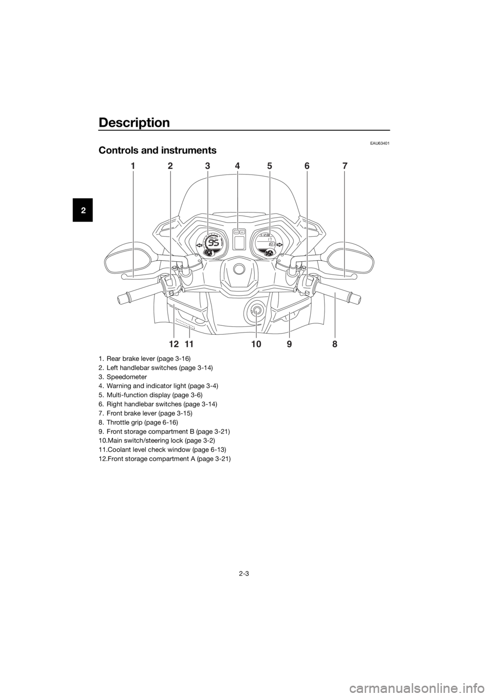
Controls and instruments
98765432111 10
120
1000r/minx
E
FCH
FSELECTRESET
417 5 362
891011 12
1. Rear brake lever (page 3-16)
2. Left handlebar switches (page 3-14)
3. Speedometer
4. Warning and indicator light (page 3-4)
5. Multi-function display (page 3-6)
6. Right handlebar switches (page 3-14)
7. Front brake lever (page 3-15)
8. Throttle grip (page 6-16)
9. Front storage compartment B (page 3-21)
10.Main switch/steering lock (page 3-2)
11.Coolant level check window (page 6-13)
12.Front storage compartment A (page 3-21)
U2DLE2E0.book Page 3 Thursday, July 2, 2015 6:20 PM
Page 16 of 96
Instrument and control functions
3-2
3Keep the standard keys as well
as keys of other immobilizer
systems away from this vehi-
cle’s code re-registering key.
Keep other immobilizer system
keys away from the main switch
as they may cause signal inter-
ference.
EAU10474
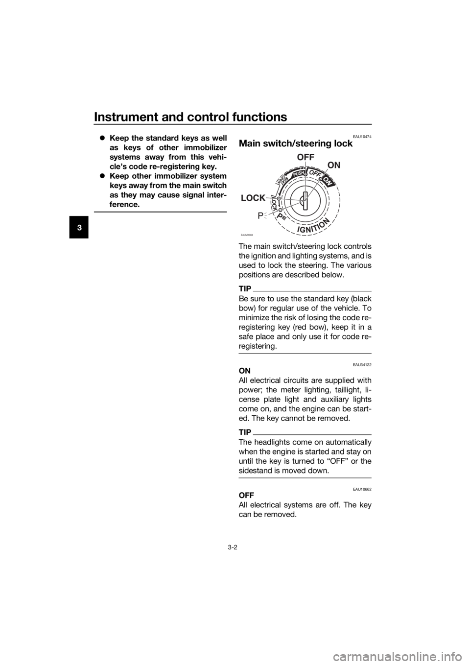
Main switch/steering lock
The main switch/steering lock controls
the ignition and lighting systems, and is
used to lock the steering. The various
positions are described below.
TIP
Be sure to use the standard key (black
bow) for regular use of the vehicle. To
minimize the risk of losing the code re-
registering key (red bow), keep it in a
safe place and only use it for code re-
registering.
EAU34122ON
All electrical circuits are supplied with
power; the meter lighting, taillight, li-
cense plate light and auxiliary lights
come on, and the engine can be start-
ed. The key cannot be removed.
TIP
The headlights come on automatically
when the engine is started and stay on
sidestand is moved down.
EAU10662OFF
All electrical systems are off. The key
can be removed.
ZAUM1004
U2DLE2E0.book Page 2 Thursday, July 2, 2015 6:20 PM
Page 17 of 96
Instrument and control functions
3-3
3
WARNING
EWA10062
Never turn the key to “OFF” or
“LOCK” while the vehicle is moving.
Otherwise the electrical systems will
be switched off, which may result in
loss of control or an accident.
EAU10686LOCK
The steering is locked and all electrical
systems are off. The key can be re-
moved.
To lock the steering
1. Turn the handlebars all the way to
the left.
2. With the key in the “OFF” position,
push the key in and turn it to
“LOCK”.
3. Remove the key.
TIP
If the steering will not lock, try turning
the handlebars back to the right slight-
ly.
To unlock the steering
1. Insert the key.
2.
tion, push the key in and turn it to
EAU59680 (Parking)
The hazard lights and turn signal lights
can be turned on, but all other electri-
cal systems are off. The key can be re-
moved.
The steering must be locked before the
key can be turned to “ ”.
NOTICE
ECA20760
Using the hazard or turn signal lights
for an extended length of time may
cause the battery to discharge.
U2DLE2E0.book Page 3 Thursday, July 2, 2015 6:20 PM
Page 18 of 96
Instrument and control functions
3-4
3
EAU49398
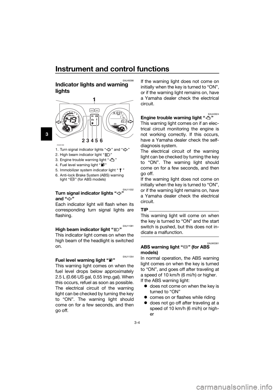
Indicator lights and warning
lights
EAU11032Turn signal indicator lights “ ”
and“”
Each indicator light will flash when its
corresponding turn signal lights are
flashing.
EAU11081High beam indicator light “ ”
This indicator light comes on when the
high beam of the headlight is switched
on.
EAU11354Fuel level warning light “ ”
This warning light comes on when the
fuel level drops below approximately
2.5 L (0.66 US gal, 0.55 Imp.gal). When
this occurs, refuel as soon as possible.
The electrical circuit of the warning
light can be checked by turning the key
to “ON”. The warning light should
come on for a few seconds, and then
go off.If the warning light does not come on
initially when the key is turned to “ON”,
or if the warning light remains on, have
a Yamaha dealer check the electrical
circuit.
EAU43024Engine trouble warning light “ ”
This warning light comes on if an elec-
trical circuit monitoring the engine is
not working correctly. If this occurs,
have a Yamaha dealer check the self-
diagnosis system.
The electrical circuit of the warning
light can be checked by turning the key
to “ON”. The warning light should
come on for a few seconds, and then
go off.
If the warning light does not come on
initially when the key is turned to “ON”,
or if the warning light remains on, have
a Yamaha dealer check the electrical
circuit.
TIP
This warning light will come on when
switch is pushed, but this does not in-
dicate a malfunction.
EAUM3381ABS warning light “ ” (for ABS
models)
In normal operation, the ABS warning
light comes on when the key is turned
to “ON”, and goes off after traveling at
a speed of 10 km/h (6 mi/h) or higher.
If the ABS warning light:
does not come on when the key is
turned to “ON”
comes on or flashes while riding
does not go off after traveling at a
speed of 10 km/h (6 mi/h) or high-
er
1. Turn signal indicator lights “ ” and “ ”
2. High beam indicator light “ ”
3. Engine trouble warning light “ ”
4. Fuel level warning light “ ”
5. Immobilizer system indicator light “ ”
6. Anti-lock Brake System (ABS) warning
light “ ” (for ABS models)
ZAUM109823456
98765432111 10
12
0
1000r/minx
km/h
E
FCH
kmOdoOdoSELECTRESET
11
ABS
ABS
U2DLE2E0.book Page 4 Thursday, July 2, 2015 6:20 PM
Page 19 of 96
Instrument and control functions
3-5
3 The ABS may not work correctly. If any
of the above occurs, have a Yamaha
dealer check the system as soon as
possible. (See page 3-16 for an expla-
nation of the ABS.)
WARNING
EWA16041
If the ABS warning light does not go
off after traveling at a speed of 10
km/h (6 mi/h) or higher, or if the
warning light comes on or flashes
while riding, the brake system re-
verts to conventional braking. If ei-
ther of the above occurs, or if the
warning light does not come on at
all, use extra caution to avoid possi-
ble wheel lock during emergency
braking. Have a Yamaha dealer
check the brake system and electri-
cal circuits as soon as possible.
TIP
The ABS warning light may come on
while accelerating the engine with the
scooter on its centerstand, but this
does not indicate a malfunction.
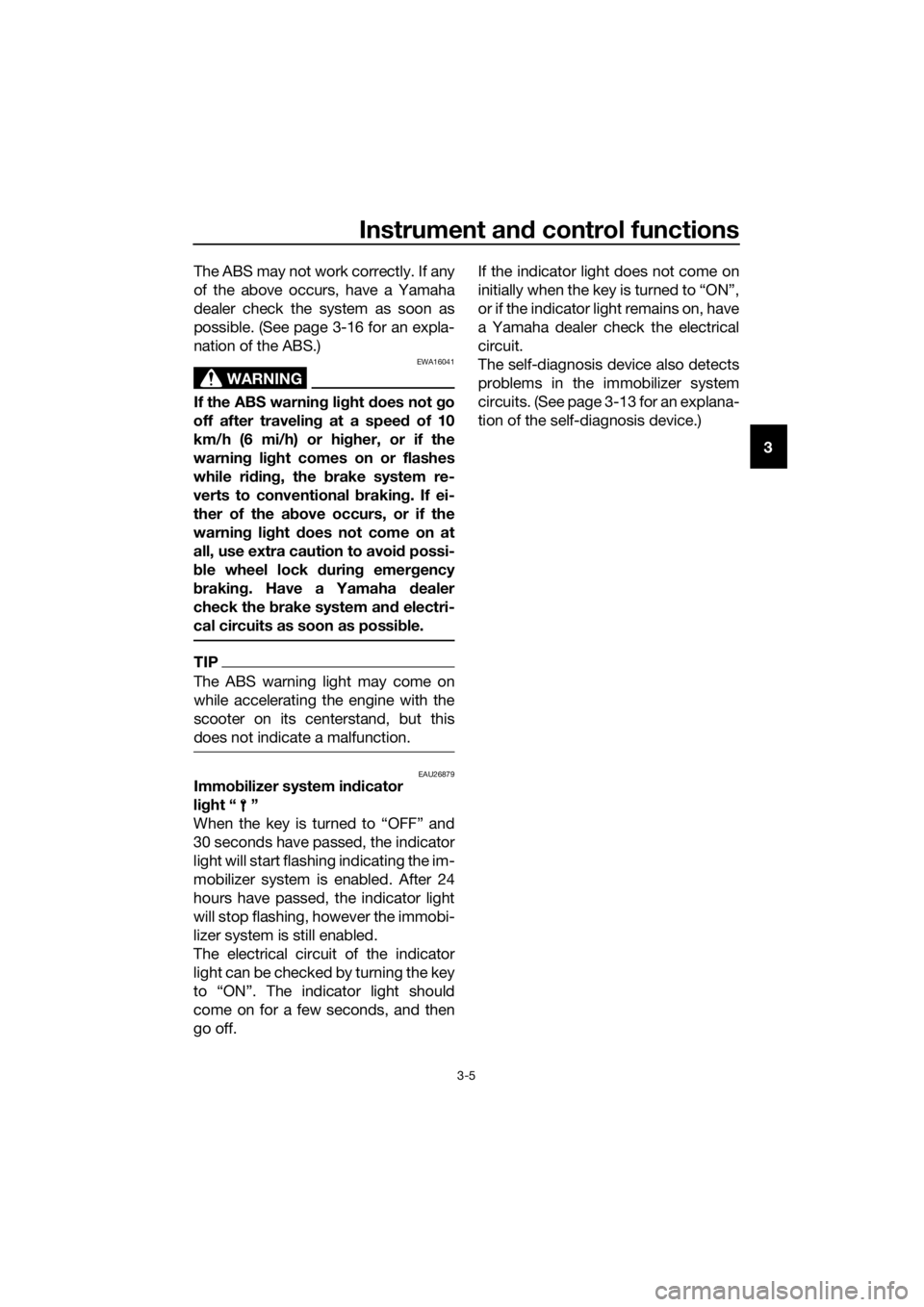
EAU26879Immobilizer system indicator
light “ ”
When the key is turned to “OFF” and
30 seconds have passed, the indicator
light will start flashing indicating the im-
mobilizer system is enabled. After 24
hours have passed, the indicator light
will stop flashing, however the immobi-
lizer system is still enabled.
The electrical circuit of the indicator
light can be checked by turning the key
to “ON”. The indicator light should
come on for a few seconds, and then
go off.If the indicator light does not come on
initially when the key is turned to “ON”,
or if the indicator light remains on, have
a Yamaha dealer check the electrical
circuit.
The self-diagnosis device also detects
problems in the immobilizer system
circuits. (See page 3-13 for an explana-
tion of the self-diagnosis device.)
U2DLE2E0.book Page 5 Thursday, July 2, 2015 6:20 PM
Page 20 of 96
Instrument and control functions
3-6
3
EAUM3313
Multi-function meter unit
WARNING
EWA12423
Be sure to stop the vehicle before
making any setting changes to the
multi-function meter unit. Changing
settings while riding can distract the
operator and increase the risk of an
accident.
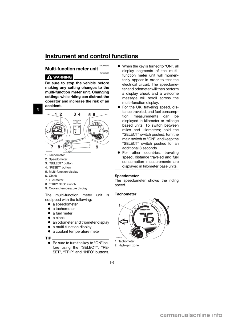
The multi-function meter unit is
equipped with the following:
a speedometer
a tachometer
a fuel meter
a clock
an odometer and tripmeter display
a multi-function display
a coolant temperature meter
TIP
Be sure to turn the key to “ON” be-
fore using the “SELECT”, “RE-
SET”, “TRIP” and “INFO” buttons.When the key is turned to “ON”, all
display segments of the multi-
function meter unit will momen-
tarily appear in order to test the
electrical circuit. The speedome-
ter and odometer will then perform
a display check and a welcome
message will scroll across the
multi-function display.
For the UK, traveling speed, dis-
tance traveled, and fuel consump-
tion measurements can be
displayed in kilometer or mileage
based units. To switch between
miles and kilometers; hold the
“SELECT” switch pushed, turn the
main switch to “ON”, and keep the
“SELECT” switch pushed for an
additional 8 seconds.
For other countries, traveling
speed, distance traveled and fuel
consumption measurements are
displayed in kilometer base units.
Speedometer
The speedometer shows the riding
speed.
Tachometer
1. Tachometer
2. Speedometer
3. “SELECT” button
4. “RESET” button
5. Multi-function display
6. Clock
7. Fuel meter
8. “TRIP/INFO” switch
9. Coolant temperature display
ZAUM1099
3
98765432111 10
12
0
1000r/minx
km/h
E
FCH
kmOdo
AirA
veCo
ns
OilV- Be
ltTi
meTr ipOdoSELECTRESETF
465
7
21
8
9INFOTRIP
1. Tachometer
2. High-rpm zone
ZAUM1136
19876543
2
1
11 10
12
0
1000r/minx
km/h
E
F
2
U2DLE2E0.book Page 6 Thursday, July 2, 2015 6:20 PM
Page 21 of 96
Instrument and control functions
3-7
3 The electric tachometer allows the rid-
er to monitor the engine speed and
keep it within the ideal power range.
NOTICE
ECAM1150
Do not operate the engine in the ta-
chometer high-rpm zone.
High-rpm zone: 8000 r/min and
above
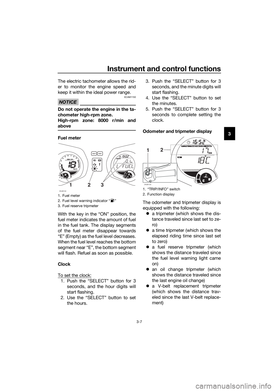
Fuel meter
With the key in the “ON” position, the
fuel meter indicates the amount of fuel
in the fuel tank. The display segments
of the fuel meter disappear towards
“E” (Empty) as the fuel level decreases.
When the fuel level reaches the bottom
segment near “E”, the bottom segment
will flash. Refuel as soon as possible.
Clock
To set the clock:
1. Push the “SELECT” button for 3
seconds, and the hour digits will
start flashing.
2. Use the “SELECT” button to set
the hours.3. Push the “SELECT” button for 3
seconds, and the minute digits will
start flashing.
4. Use the “SELECT” button to set
the minutes.
5. Push the “SELECT” button for 3
seconds to complete setting the
clock.
Odometer and tripmeter display
The odometer and tripmeter display is
equipped with the following:
a tripmeter (which shows the dis-
tance traveled since last set to ze-
ro)
a time tripmeter (which shows the
elapsed riding time since last set
to zero)
a fuel reserve tripmeter (which
shows the distance traveled since
the fuel level warning light came
on)
an oil change tripmeter (which
shows the distance traveled since
the last engine oil change)
a V-belt replacement tripmeter
(which shows the distance trav-
eled since the last V-belt replace-
ment)
1. Fuel meter
2. Fuel level warning indicator “ ”
3. Fuel reserve tripmeter
ZAUM1102
98765432111 10
12
0
1000r/min
km/h
E
FCH
kmT
ripOdo
SELECTRESET
F
3121.
2. Function display
ZAUM1104CH
km
Odo
Air
OilV- B e l tTimeT
ripOdoF
21
INFOTRIP
U2DLE2E0.book Page 7 Thursday, July 2, 2015 6:20 PM
Page 30 of 96
Instrument and control functions
3-16
3
EAU12952
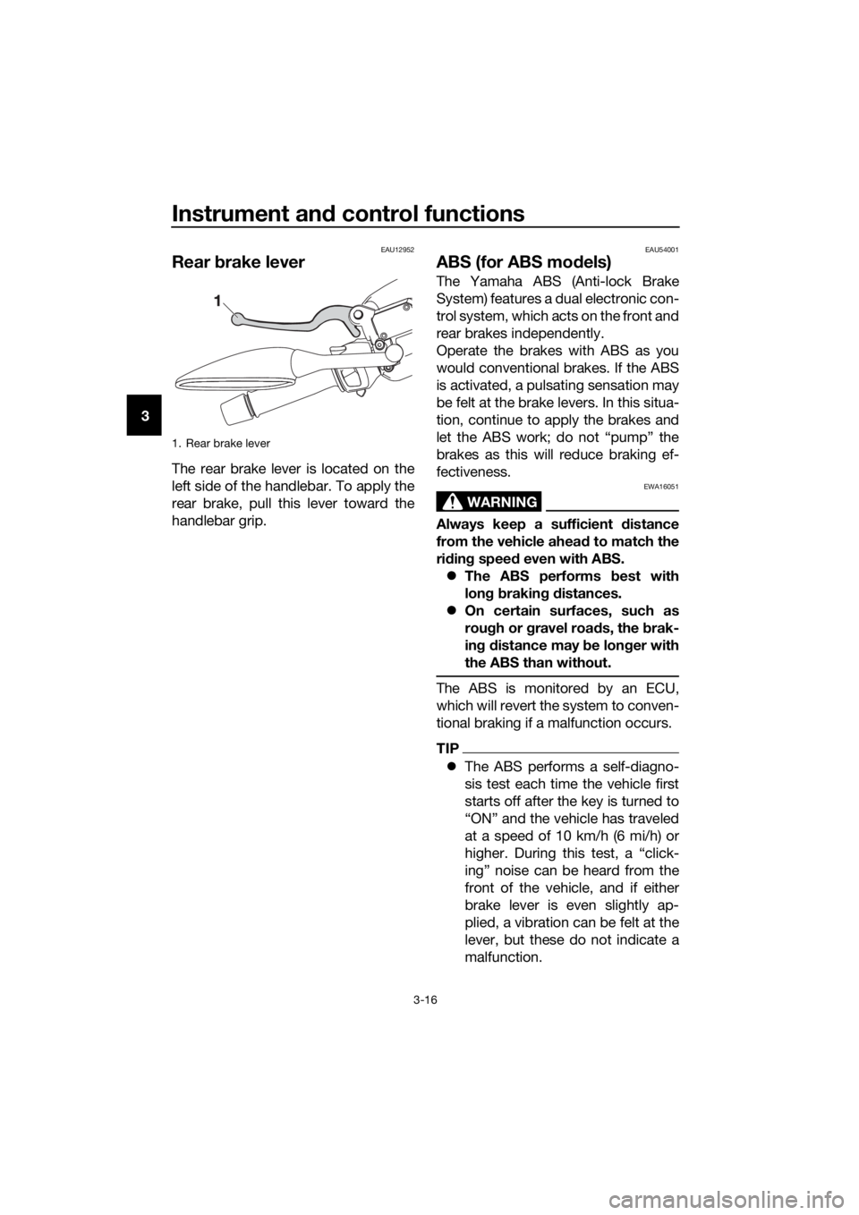
Rear brake lever
The rear brake lever is located on the
left side of the handlebar. To apply the
rear brake, pull this lever toward the
handlebar grip.
EAU54001
ABS (for ABS models)
The Yamaha ABS (Anti-lock Brake
System) features a dual electronic con-
trol system, which acts on the front and
rear brakes independently.
Operate the brakes with ABS as you
would conventional brakes. If the ABS
is activated, a pulsating sensation may
be felt at the brake levers. In this situa-
tion, continue to apply the brakes and
let the ABS work; do not “pump” the
brakes as this will reduce braking ef-
fectiveness.
WARNING
EWA16051
Always keep a sufficient distance
from the vehicle ahead to match the
riding speed even with ABS.
The ABS performs best with
long braking distances.
On certain surfaces, such as
rough or gravel roads, the brak-
ing distance may be longer with
the ABS than without.
The ABS is monitored by an ECU,
which will revert the system to conven-
tional braking if a malfunction occurs.
TIP
The ABS performs a self-diagno-
sis test each time the vehicle first
starts off after the key is turned to
“ON” and the vehicle has traveled
at a speed of 10 km/h (6 mi/h) or
higher. During this test, a “click-
ing” noise can be heard from the
front of the vehicle, and if either
brake lever is even slightly ap-
plied, a vibration can be felt at the
lever, but these do not indicate a
malfunction.
1. Rear brake lever
U2DLE2E0.book Page 16 Thursday, July 2, 2015 6:20 PM
Page 31 of 96
Instrument and control functions
3-17
3 This ABS has a test mode which
allows the owner to experience
the pulsation at the brake levers
when the ABS is operating. How-
ever, special tools are required, so
please consult your Yamaha deal-
er when performing this test.
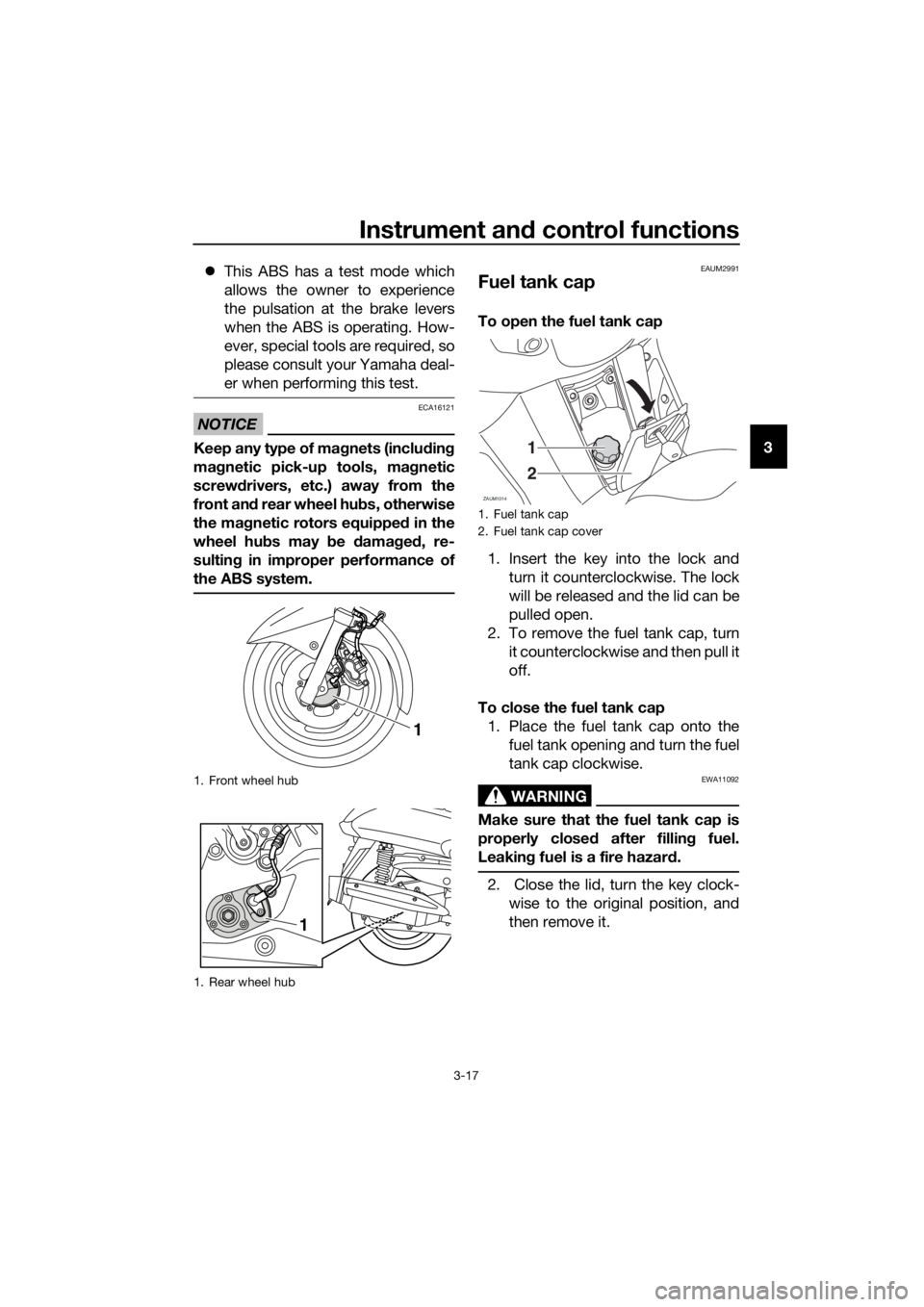
NOTICE
ECA16121
Keep any type of magnets (including
magnetic pick-up tools, magnetic
screwdrivers, etc.) away from the
front and rear wheel hubs, otherwise
the magnetic rotors equipped in the
wheel hubs may be damaged, re-
sulting in improper performance of
the ABS system.
EAUM2991
Fuel tank cap
To open the fuel tank cap
1. Insert the key into the lock and
turn it counterclockwise. The lock
will be released and the lid can be
pulled open.
2. To remove the fuel tank cap, turn
it counterclockwise and then pull it
off.
To close the fuel tank cap
1. Place the fuel tank cap onto the
fuel tank opening and turn the fuel
tank cap clockwise.
WARNING
EWA11092
Make sure that the fuel tank cap is
properly closed after filling fuel.
Leaking fuel is a fire hazard.
2. Close the lid, turn the key clock-
wise to the original position, and
then remove it.
1. Front wheel hub
1. Rear wheel hub
1
1
1. Fuel tank cap
2. Fuel tank cap cover
ZAUM1014
1
2
U2DLE2E0.book Page 17 Thursday, July 2, 2015 6:20 PM