change time YAMAHA XMAX 300 2021 Owners Manual
[x] Cancel search | Manufacturer: YAMAHA, Model Year: 2021, Model line: XMAX 300, Model: YAMAHA XMAX 300 2021Pages: 114, PDF Size: 4.65 MB
Page 31 of 114
Instrument and control functions
4-4
4
EAU78486
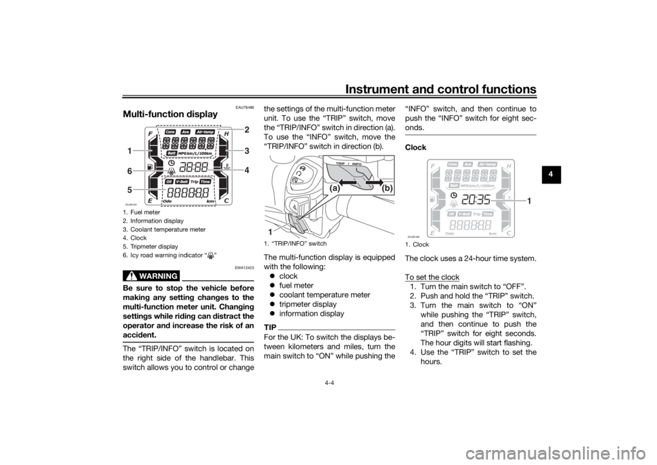
Multi-function display
WARNING
EWA12423
Be sure to stop the vehicle before
makin g any settin g chan ges to the
multi-function meter unit. Chan gin g
settin gs while ri din g can distract the
operator an d increase the risk of an
acci dent.The “TRIP/INFO” switch is located on
the right side of the handlebar. This
switch allows you to control or change the settings of the multi-function meter
unit. To use the “TRIP” switch, move
the “TRIP/INFO” switch in direction (a).
To use the “INFO” switch, move the
“TRIP/INFO” switch in direction (b).
The multi-function display is equipped
with the following:
clock
fuel meter
coolant temperature meter
tripmeter display
information display
TIPFor the UK: To switch the displays be-
tween kilometers and miles, turn the
main switch to “ON” while pushing the “INFO” switch, and then continue to
push the “INFO” switch for eight sec-
onds.
Clock
The clock uses a 24-hour time system.
To set the clock1. Turn the main switch to “OFF”.
2. Push and hold the “TRIP” switch.
3. Turn the main switch to “ON”
while pushing the “TRIP” switch,
and then continue to push the
“TRIP” switch for eight seconds.
The hour digits will start flashing.
4. Use the “TRIP” switch to set the hours.
1. Fuel meter
2. Information display
3. Coolant temperature meter
4. Clock
5. Tripmeter display
6. Icy road warning indicator “ ”ZAUM1481
234
165
1. “TRIP/INFO” switch1 (b)
(a)
1. ClockZAUM1482
1
UBBAE0E0.book Page 4 Thursday, September 24, 2020 3:19 PM
Page 33 of 114
Instrument and control functions
4-6
4
Tripmeter
display
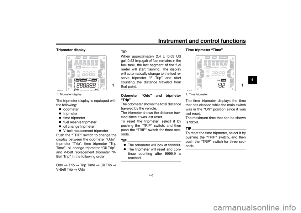
The tripmeter display is equipped with
the following: odometer
tripmeter
time tripmeter
fuel reserve tripmeter
oil change tripmeter
V-belt replacement tripmeter
Push the “TRIP” switch to change the
display between the odometer “Odo”,
tripmeter “Trip”, time tripmeter “Trip
Time”, oil change tripmeter “Oil Trip”,
and V-belt replacement tripmeter “V-
Belt Trip” in the following order:
Odo → Trip → Trip Time → Oil Trip →
V-Belt Trip → Odo
TIPWhen approximately 2.4 L (0.63 US
gal, 0.53 Imp.gal) of fuel remains in the
fuel tank, the last segment of the fuel
meter will start flashing. The display
will automatically change to the fuel re-
serve tripmeter “F Trip” and start
counting the distance traveled from
that point.Odometer “O do” an d tripmeter
“Trip”
The odometer shows the total distance
traveled by the vehicle.
The tripmeter shows the distance trav-
eled since it was last reset.
To reset the tripmeter, select it by
pushing the “TRIP” switch, and then
push the “TRIP” switch for three sec-
onds.TIP The odometer will lock at 999999.
The tripmeter will reset and con-
tinue counting after 9999.9 is
reached.
Time tripmeter “Time”
The time tripmeter displays the time
that has elapsed while the main switch
was in the “ON” position since it was
last reset.
The maximum time that can be shown
is 99:59.TIPTo reset the time tripmeter, select it by
pushing the “TRIP” switch, and then
push the “TRIP” switch for three sec-
onds.
1. Tripmeter displayZAUM1485
1
1. Time tripmeterZAUM1486
1
UBBAE0E0.book Page 6 Thursday, September 24, 2020 3:19 PM
Page 34 of 114
Instrument and control functions
4-7
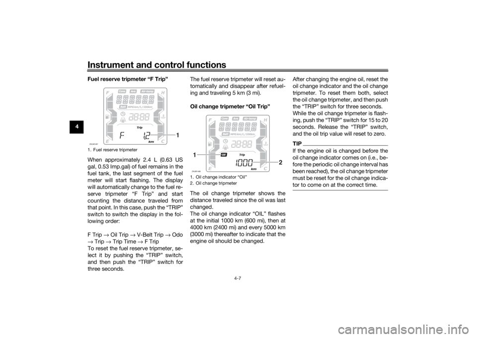
4 Fuel reserve tripmeter “F Trip”
When approximately 2.4 L (0.63 US
gal, 0.53 Imp.gal) of fuel remains in the
fuel tank, the last segment of the fuel
meter will start flashing. The display
will automatically change to the fuel re-
serve tripmeter “F Trip” and start
counting the distance traveled from
that point. In this case, push the “TRIP”
switch to switch the display in the fol-
lowing order:
F Trip
→ Oil Trip → V-Belt Trip → Odo
→ Trip → Trip Time → F Trip
To reset the fuel reserve tripmeter, se-
lect it by pushing the “TRIP” switch,
and then push the “TRIP” switch for
three seconds. The fuel reserve tripmeter will reset au-
tomatically and disappear after refuel-
ing and traveling 5 km (3 mi).
Oil chan
ge tripmeter “Oil Trip”
The oil change tripmeter shows the
distance traveled since the oil was last
changed.
The oil change indicator “OIL” flashes
at the initial 1000 km (600 mi), then at
4000 km (2400 mi) and every 5000 km
(3000 mi) thereafter to indicate that the
engine oil should be changed. After changing the engine oil, reset the
oil change indicator and the oil change
tripmeter. To reset them both, select
the oil change tripmeter, and then push
the “TRIP” switch for three seconds.
While the oil change tripmeter is flash-
ing, push the “TRIP” switch for 15 to 20
seconds. Release the “TRIP” switch,
and the oil trip value will reset to zero.
TIPIf the engine oil is changed before the
oil change indicator comes on (i.e., be-
fore the periodic oil change interval has
been reached), the oil change tripmeter
must be reset for the oil change indica-
tor to come on at the correct time.
1. Fuel reserve tripmeterZAUM1487
1
1. Oil change indicator “Oil”
2. Oil change tripmeterZAUM14881
2
UBBAE0E0.book Page 7 Thursday, September 24, 2020 3:19 PM
Page 35 of 114

Instrument and control functions
4-8
4
V-
belt replacement tripmeter “V-
Belt Trip”
The V-belt replacement tripmeter
shows the distance traveled since the
V-belt was last replaced.
The V-belt replacement indicator “V-
Belt” will flash every 20000 km (12000
mi) to indicate that the V-belt should be
replaced.
After replacing the V-belt, reset the V-
belt replacement indicator and the V-
belt replacement tripmeter. To reset
them both, select the V-belt replace-
ment tripmeter, and then push the
“TRIP” switch for three seconds. While the V-belt replacement tripmeter
is flashing, push the “TRIP” switch for
15 to 20 seconds. Release the “TRIP”
switch, and the V-belt trip value will re-
set to zero.
TIPIf the V-belt is replaced before the V-
belt replacement indicator comes on
(i.e., before the periodic V-belt replace-
ment interval has been reached), the V-
belt replacement tripmeter must be re-
set for the V-belt replacement indicator
to come on at the correct time.Information
display
The information display is equipped
with the following:
air temperature display
battery voltage display
traction control system display
average fuel consumption display
instantaneous fuel consumption
display
average speed display
warning message function
Navi gatin g the information d isplay
Push the “INFO” switch to change the
display between the air temperature
display “Air-temp”, battery voltage dis-
play “Battery”, traction control system
display “TCS ON” or “TCSOFF”, aver-
age fuel consumption display “Con-
sumption/Average_ _._ km/L” or
“Consumption/Average_ _._ L/100
km”, instantaneous fuel consumption
display “Consumption_ _._ km/L” or
“Consumption_ _._ L/100 km” and av-
erage speed display “Average” in the
following order:
Air-temp → Battery → TCS ON or TC-
SOFF → Consumption/Average_ _._
km/L → Consumption/Average_ _._
1. V-belt replacement indicator “V-Belt”
2. V-belt replacement tripmeterZAUM14891
2
1. Information displayZAUM1490
1
UBBAE0E0.book Page 8 Thursday, September 24, 2020 3:19 PM
Page 40 of 114

Instrument and control functions
4-13
4
EAU54213
Stop/Run/Start switch “ / / ”
To crank the engine with the starter,
set this switch to “ ”, and then push
the switch down towards “ ”. See
page 6-2 for starting instructions prior
to starting the engine.
Set this switch to “ ” to stop the en-
gine in case of an emergency, such as
when the vehicle overturns or when the
throttle cable is stuck.
EAU78190
Hazar d switch “ ”
With the main switch in the “ON”
or “ ” position, use this switch to turn
on the hazard lights (simultaneous
flashing of all turn signal lights).
The hazard lights are used in case of an
emergency or to warn other drivers
when your vehicle is stopped where it
might be a traffic hazard.NOTICE
ECA10062
Do not use the hazard lights for an
exten ded len gth of time with the en-
g ine not runnin g, otherwise the bat-
tery may dischar ge.
EAU78491
“TRIP/INFO” switch
This switch is used to make setting and
display changes in the multi-function
meter unit. See page 4-4 for more in-
formation.
To use the “TRIP” switch, move the
“TRIP/INFO” switch in direction (a). To
use the “INFO” switch, move the
“TRIP/INFO” switch in direction (b).
EAU12902
Front brake leverThe front brake lever is located on the
right side of the handlebar. To apply
the front brake, pull this lever toward
the throttle grip.
1. “TRIP/INFO” switch1 (b)
(a)
1. Front brake lever
1
UBBAE0E0.book Page 13 Thursday, September 24, 2020 3:19 PM
Page 74 of 114
Periodic maintenance an d a djustment
7-12
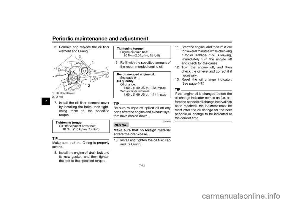
7 6. Remove and replace the oil filter
element and O-ring.
7. Install the oil filter element cover by installing the bolts, then tight-
ening them to the specified
torque.
TIPMake sure that the O-ring is properly
seated.8. Install the engine oil drain bolt andits new gasket, and then tighten
the bolt to the specified torque. 9. Refill with the specified amount of
the recommended engine oil.
TIPBe sure to wipe off spilled oil on any
parts after the engine and exhaust sys-
tem have cooled down.NOTICE
ECA24060
Make sure that no forei gn material
enters the crankcase.10. Install and tighten the oil filler cap and its O-ring. 11. Start the engine, and then let it idle
for several minutes while checking
it for oil leakage. If oil is leaking,
immediately turn the engine off
and check for the cause.
12. Turn the engine off, and then check the oil level and correct it if
necessary.
13. Reset the oil change indicator. (See page 4-7.)
TIPIf the engine oil is changed before the
oil change indicator comes on (i.e. be-
fore the periodic oil change interval has
been reached), the indicator must be
reset after the oil change for the next
periodic oil change to be indicated at
the correct time.
1. Oil filter element
2. O-ringTightenin g torque:
Oil filter element cover bolt: 10 N·m (1.0 kgf·m, 7.4 lb·ft)
1
2
Tightenin g torque:
Engine oil drain bolt:
20 N·m (2.0 kgf·m, 15 lb·ft)
Recommen ded en gine oil:
See page 9-1.
Oil quantity:
Oil change:1.50 L (1.59 US qt, 1.32 Imp.qt)
With oil filter removal:
1.60 L (1.69 US qt, 1.41 Imp.qt)
UBBAE0E0.book Page 12 Thursday, September 24, 2020 3:19 PM
Page 82 of 114
Periodic maintenance an d a djustment
7-20
7
EAU21403
Valve clearanceThe valves are an important engine
component, and since valve clearance
changes with use, they must be
checked and adjusted at the intervals
specified in the periodic maintenance
chart. Unadjusted valves can result in
improper air-fuel mixture, engine
noise, and eventually engine damage.
To prevent this from occurring, have
your Yamaha dealer check and adjust
the valve clearance at regular intervals.TIPThis service must be performed when
the engine is cold.
EAU69761
TiresTires are the only contact between the
vehicle and the road. Safety in all con-
ditions of riding depends on a relatively
small area of road contact. Therefore, it
is essential to maintain the tires in good
condition at all times and replace them
at the appropriate time with the speci-
fied tires.
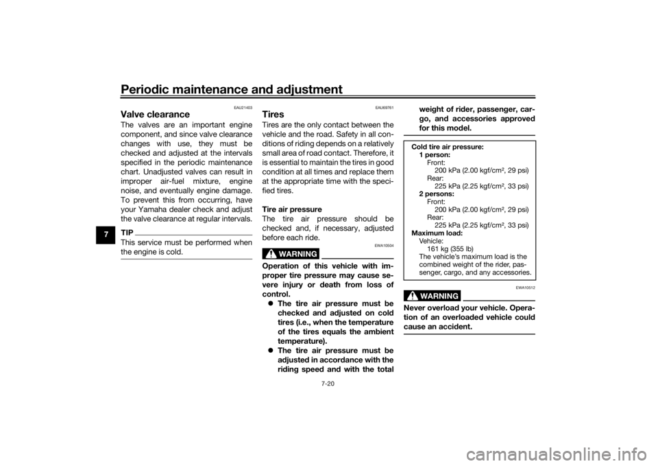
Tire air pressure
The tire air pressure should be
checked and, if necessary, adjusted
before each ride.
WARNING
EWA10504
Operation of this vehicle with im-
proper tire pressure may cause se-
vere injury or death from loss of
control. The tire air pressure must be
checked and a djuste d on col d
tires (i.e., when the temperature
of the tires equals the am bient
temperature).
The tire air pressure must be
a d juste d in accor dance with the
ri din g speed and with the total wei
ght of ri der, passen ger, car-
g o, an d accessories approve d
for this mo del.
WARNING
EWA10512
Never overloa d your vehicle. Opera-
tion of an overload ed vehicle coul d
cause an acci dent.Col d tire air pressure:
1 person: Front:200 kPa (2.00 kgf/cm², 29 psi)
Rear: 225 kPa (2.25 kgf/cm², 33 psi)
2 persons:
Front:200 kPa (2.00 kgf/cm², 29 psi)
Rear:
225 kPa (2.25 kgf/cm², 33 psi)
Maximum load :
Vehicle:
161 kg (355 lb)
The vehicle’s maximum load is the
combined weight of the rider, pas-
senger, cargo, and any accessories.
UBBAE0E0.book Page 20 Thursday, September 24, 2020 3:19 PM