check engine light YAMAHA XMAX 400 2014 User Guide
[x] Cancel search | Manufacturer: YAMAHA, Model Year: 2014, Model line: XMAX 400, Model: YAMAHA XMAX 400 2014Pages: 92, PDF Size: 7.3 MB
Page 59 of 92

PERIODIC MAINTENANCE AND ADJUSTMENT
6-16
6
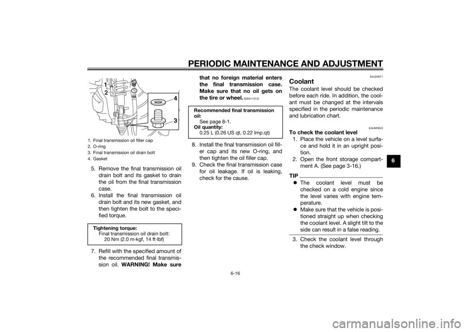
5. Remove the final transmission oil
drain bolt and its gasket to drain
the oil from the final transmission
case.
6. Install the final transmission oil
drain bolt and its new gasket, and
then tighten the bolt to the speci-
fied torque.
7. Refill with the specified amount of
the recommended final transmis-
sion oil. WARNING! Make surethat no foreign material enters
the final transmission case.
Make sure that no oil gets on
the tire or wheel.
[EWA11312]
8. Install the final transmission oil fill-
er cap and its new O-ring, and
then tighten the oil filler cap.
9. Check the final transmission case
for oil leakage. If oil is leaking,
check for the cause.
EAU20071
CoolantThe coolant level should be checked
before each ride. In addition, the cool-
ant must be changed at the intervals
specified in the periodic maintenance
and lubrication chart.
EAUM3043
To check the coolant level
1. Place the vehicle on a level surfa-
ce and hold it in an upright posi-
tion.
2. Open the front storage compart-
ment A. (See page 3-16.)TIPThe coolant level must be
checked on a cold engine since
the level varies with engine tem-
perature.
Make sure that the vehicle is posi-
tioned straight up when checking
the coolant level. A slight tilt to the
side can result in a false reading.3. Check the coolant level through
the check window.
1. Final transmission oil filler cap
2. O-ring
3. Final transmission oil drain bolt
4. GasketTightening torque:
Final transmission oil drain bolt:
20 Nm (2.0 m·kgf, 14 ft·lbf)
21
34
Recommended final transmission
oil:
See page 8-1.
Oil quantity:
0.25 L (0.26 US qt, 0.22 Imp.qt)
U1SDE1E0.book Page 16 Monday, September 23, 2013 3:55 PM
Page 63 of 92

PERIODIC MAINTENANCE AND ADJUSTMENT
6-20
6 5. Lightly tap the V-belt case air filter
element to remove most of the
dust and dirt, and then blow out
the dirt with compressed air as
shown.
6. Check the V-belt case air filter ele-
ment for damage and replace it if
necessary.
7. Install the V-belt case air filter ele-
ment by installing the screws.
NOTICE: Make sure that the V-
belt filter element is properly
seated in its case.
[ECA12942]
8. Install the V-belt air filter case cov-
er by installing the screws.
9. Install the left air filter case cover.
10. Install the panel.
EAU21385
Checking the throttle grip free
playThe throttle grip free play should mea-
sure 3.0–5.0 mm (0.12–0.20 in) at the
inner edge of the throttle grip. Periodi-
cally check the throttle grip free play
and, if necessary, have a Yamaha deal-
er adjust it.
EAU21402
Valve clearanceThe valve clearance changes with use,
resulting in improper air-fuel mixture
and/or engine noise. To prevent this
from occurring, the valve clearance
must be adjusted by a Yamaha dealer
at the intervals specified in the periodic
maintenance and lubrication chart.
1. Throttle grip free play
U1SDE1E0.book Page 20 Monday, September 23, 2013 3:55 PM
Page 89 of 92

10-1
10
INDEX
AABS (for ABS models) .......................... 3-12
ABS warning light (for ABS models) ....... 3-4
Acceleration and deceleration ................ 5-3
Air filter elements and check hoses
and V-belt case air filter element ....... 6-18
Anti-theft alarm (optional) ..................... 3-10
Auxiliary light ........................................ 6-35BBattery .................................................. 6-29
Brake fluid, changing............................ 6-26
Brake fluid level, checking.................... 6-24
Brake lever, front .................................. 3-11
Brake lever, rear ................................... 3-12
Brake levers, lubricating ....................... 6-27
Braking ................................................... 5-3CCables, checking and lubricating ......... 6-26
Care ........................................................ 7-1
Catalytic converters.............................. 3-15
Centerstand and sidestand, checking
and lubricating ................................... 6-27
Coolant ................................................. 6-16DDimmer switch...................................... 3-11EEngine break-in ...................................... 5-4
Engine oil and oil filter element............. 6-13
Engine trouble warning light ................... 3-4FFinal transmission oil ............................ 6-15
Front and rear brake lever free play,
checking ............................................. 6-23
Front and rear brake pads, checking ... 6-24Front fork, checking ............................. 6-28
Front turn signal light ........................... 6-33
Fuel ...................................................... 3-14
Fuel consumption, tips for reducing ...... 5-4
Fuel tank cap........................................ 3-13
Fuses, replacing ................................... 6-31
HHandlebar switches ............................. 3-10
Hazard switch ...................................... 3-11
Headlight bulb, replacing ..................... 6-32
High beam indicator light ....................... 3-4
Horn switch .......................................... 3-11IIdentification numbers ........................... 9-1
Ignition circuit cut-off system .............. 3-19
Immobilizer system ................................ 3-1
Immobilizer system indicator light ......... 3-4
Indicator lights and warning lights ......... 3-3LLicense plate light bulb, replacing ....... 6-34MMain switch/steering lock ...................... 3-2
Maintenance and lubrication, periodic... 6-4
Maintenance, emission control
system ................................................. 6-3
Matte color, caution ............................... 7-1
Model label............................................. 9-1
Multi-function display............................. 3-6PPanels, removing and installing ............. 6-8
Parking ................................................... 5-5
Part locations ......................................... 2-1
Pass switch .......................................... 3-11
SSafe-riding points ................................... 1-5
Safety information................................... 1-1
Seat....................................................... 3-16
Shock absorber assemblies,
adjusting ............................................. 3-18
Sidestand.............................................. 3-18
Spark plug, checking ............................ 6-11
Specifications ......................................... 8-1
Speedometer .......................................... 3-5
Starting off .............................................. 5-2
Starting the engine ................................. 5-1
Start switch ........................................... 3-11
Steering, checking ................................ 6-29
Storage ................................................... 7-4
Storage compartments ......................... 3-16TTachometer............................................. 3-6
Tail/brake light ...................................... 6-33
Throttle grip and cable, checking and
lubricating ........................................... 6-26
Throttle grip free play, checking ........... 6-20
Tires ...................................................... 6-21
Tool kit .................................................... 6-2
Troubleshooting .................................... 6-35
Troubleshooting charts ......................... 6-36
Turn signal indicator lights...................... 3-3
Turn signal light bulb (rear),
replacing ............................................. 6-33
Turn signal switch ................................. 3-11VValve clearance..................................... 6-20
Vehicle identification number ................. 9-1
U1SDE1E0.book Page 1 Monday, September 23, 2013 3:55 PM