key YAMAHA XMAX 400 2015 User Guide
[x] Cancel search | Manufacturer: YAMAHA, Model Year: 2015, Model line: XMAX 400, Model: YAMAHA XMAX 400 2015Pages: 92, PDF Size: 7.29 MB
Page 27 of 92
INSTRUMENT AND CONTROL FUNCTIONS
3-11
3
EAU12351
Pass switch “ ”
Press this switch to flash the headlight.
EAU12401
Dimmer switch “ / ”
Set this switch to “ ” for the high
beam and to “ ” for the low beam.
EAU12461
Turn signal switch “ / ”
To signal a right-hand turn, push this
switch to “ ”. To signal a left-hand
turn, push this switch to “ ”. When
released, the switch returns to the cen-
ter position. To cancel the turn signal
lights, push the switch in after it has re-
turned to the center position.
EAU12501
Horn switch “ ”
Press this switch to sound the horn.
EAU12722
Start switch “ ”
With the sidestand up, push this switch
while applying the front or rear brake to
crank the engine with the starter. See
page 5-1 for starting instructions prior
to starting the engine.
EAU41701
The engine trouble warning light will
come on when the key is turned to
“ON” and the start switch is pushed,
but this does not indicate a malfunc-
tion.
EAU12734
Hazard switch “ ”
With the key in the “ON” or “ ” posi-
tion, use this switch to turn on the haz-
ard lights (simultaneous flashing of all
turn signal lights).
The hazard lights are used in case of an
emergency or to warn other drivers
when your vehicle is stopped where it
might be a traffic hazard.NOTICE
ECA10062
Do not use the hazard lights for an
extended length of time with the en-
gine not running, otherwise the bat-
tery may discharge.
EAU12902
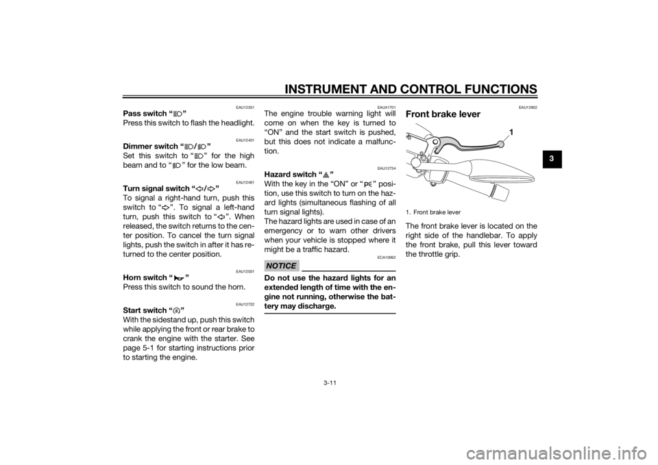
Front brake leverThe front brake lever is located on the
right side of the handlebar. To apply
the front brake, pull this lever toward
the throttle grip.1. Front brake lever
U1SDE1E0.book Page 11 Monday, September 23, 2013 3:55 PM
Page 28 of 92
INSTRUMENT AND CONTROL FUNCTIONS
3-12
3
EAU12952
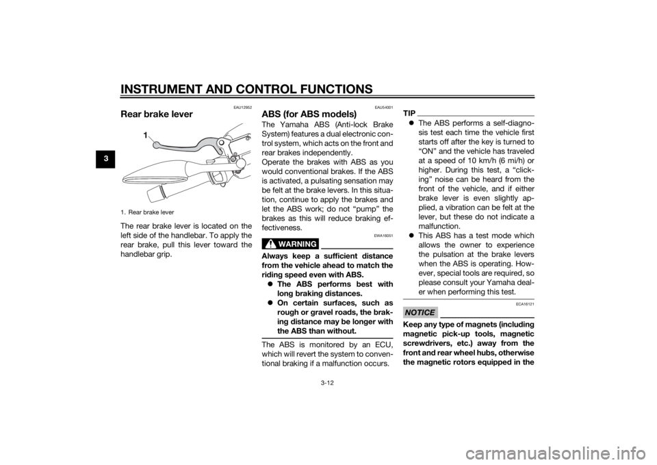
Rear brake leverThe rear brake lever is located on the
left side of the handlebar. To apply the
rear brake, pull this lever toward the
handlebar grip.
EAU54001
ABS (for ABS models)The Yamaha ABS (Anti-lock Brake
System) features a dual electronic con-
trol system, which acts on the front and
rear brakes independently.
Operate the brakes with ABS as you
would conventional brakes. If the ABS
is activated, a pulsating sensation may
be felt at the brake levers. In this situa-
tion, continue to apply the brakes and
let the ABS work; do not “pump” the
brakes as this will reduce braking ef-
fectiveness.
WARNING
EWA16051
Always keep a sufficient distance
from the vehicle ahead to match the
riding speed even with ABS.
The ABS performs best with
long braking distances.
On certain surfaces, such as
rough or gravel roads, the brak-
ing distance may be longer with
the ABS than without.The ABS is monitored by an ECU,
which will revert the system to conven-
tional braking if a malfunction occurs.
TIPThe ABS performs a self-diagno-
sis test each time the vehicle first
starts off after the key is turned to
“ON” and the vehicle has traveled
at a speed of 10 km/h (6 mi/h) or
higher. During this test, a “click-
ing” noise can be heard from the
front of the vehicle, and if either
brake lever is even slightly ap-
plied, a vibration can be felt at the
lever, but these do not indicate a
malfunction.
This ABS has a test mode which
allows the owner to experience
the pulsation at the brake levers
when the ABS is operating. How-
ever, special tools are required, so
please consult your Yamaha deal-
er when performing this test.NOTICE
ECA16121
Keep any type of magnets (including
magnetic pick-up tools, magnetic
screwdrivers, etc.) away from the
front and rear wheel hubs, otherwise
the magnetic rotors equipped in the
1. Rear brake leverU1SDE1E0.book Page 12 Monday, September 23, 2013 3:55 PM
Page 29 of 92

INSTRUMENT AND CONTROL FUNCTIONS
3-13
3 wheel hubs may be damaged, re-
sulting in improper performance of
the ABS system.
EAUM2991
Fuel tank capTo open the fuel tank cap
1. Insert the key into the lock and
turn it counterclockwise. The lock
will be released and the lid can be
pulled open.
2. To remove the fuel tank cap, turn
it counterclockwise and then pull it
off.
To close the fuel tank cap
1. Place the fuel tank cap onto the
fuel tank opening and turn the fuel
tank cap clockwise.
WARNING
EWA11092
Make sure that the fuel tank cap is
properly closed after filling fuel.
Leaking fuel is a fire hazard.2. Close the lid, turn the key clock-
wise to the original position, and
then remove it.
1. Front wheel hub
1. Rear wheel hub
1
1
1. Fuel tank cap
2. Fuel tank cap coverZAUM1014
12
U1SDE1E0.book Page 13 Monday, September 23, 2013 3:55 PM
Page 32 of 92
INSTRUMENT AND CONTROL FUNCTIONS
3-16
3
EAU13933
SeatTo open the seat
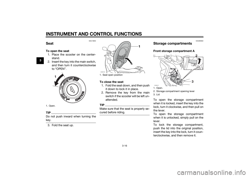
1. Place the scooter on the center-
stand.
2. Insert the key into the main switch,
and then turn it counterclockwise
to “OPEN”.TIPDo not push inward when turning the
key.3. Fold the seat up.To close the seat
1. Fold the seat down, and then push
it down to lock it in place.
2. Remove the key from the main
switch if the scooter will be left un-
attended.
TIPMake sure that the seat is properly se-
cured before riding.
EAUM3002
Storage compartmentsFront storage compartment A
To open the storage compartment
when it is locked, insert the key into the
lock, turn it clockwise, and then pull on
the lever.
To open the storage compartment
when it is unlocked, simply pull on the
lever.
To lock the storage compartment,
push the lid into the original position,
insert the key into the lock, turn it coun-
terclockwise, and then remove it.
1. Open.
1. Seat open positionZAUM1016
1. Open.
2. Storage compartment opening lever
3. LidZAUM1017
3
1 12
U1SDE1E0.book Page 16 Monday, September 23, 2013 3:55 PM
Page 36 of 92
INSTRUMENT AND CONTROL FUNCTIONS
3-20
3
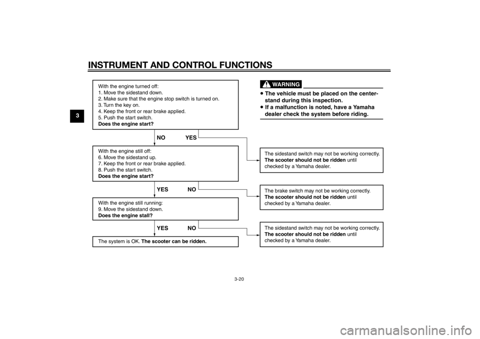
With the engine turned off:
1. Move the sidestand down.
2. Make sure that the engine stop switch is turned on.
3. Turn the key on.
4. Keep the front or rear brake applied.
5. Push the start switch.
Does the engine start?
With the engine still off:
6. Move the sidestand up.
7. Keep the front or rear brake applied.
8. Push the start switch.
Does the engine start?
With the engine still running:
9. Move the sidestand down.
Does the engine stall?
The system is OK. The scooter can be ridden.The sidestand switch may not be working correctly.
The scooter should not be ridden until
checked by a Yamaha dealer.
The sidestand switch may not be working correctly.
The scooter should not be ridden until
checked by a Yamaha dealer.
YES NO YES NO NO YES
The brake switch may not be working correctly.
The scooter should not be ridden until
checked by a Yamaha dealer.• The vehicle must be placed on the center-
stand during this inspection.• If a malfunction is noted, have a Yamaha
dealer check the system before riding.
WARNING
U1SDE1E0.book Page 20 Monday, September 23, 2013 3:55 PM
Page 39 of 92
OPERATION AND IMPORTANT RIDING POINTS
5-1
5
EAU15952
Read the Owner’s Manual carefully to
become familiar with all controls. If
there is a control or function you do not
understand, ask your Yamaha dealer.
WARNING
EWA10272
Failure to familiarize yourself with
the controls can lead to loss of con-
trol, which could cause an accident
or injury.
EAU48021
TIPThis model is equipped with a lean an-
gle sensor to stop the engine in case of
a turnover. In this case, the multi-func-
tion display indicates error code 30,
but this is not a malfunction. Turn the
the error code. Failing to do so will pre-
vent the engine from starting even
though the engine will crank when
pushing the start switch.
EAUS1893
Starting the engineNOTICE
ECA10251
See page 5-4 for engine break-in in-
structions prior to operating the ve-
hicle for the first time.In order for the ignition circuit cut-off
system to enable starting, the side-
stand must be up.
See page 3-19 for more information.
1. Turn the key to “ON”.
The following warning light, indi-
cator light and indicators should
come on for a few seconds, then
go off.
Engine trouble warning light
ABS warning light (for ABS
models)
Immobilizer system indicator
light
V-belt replacement indicator
Oil change indicator
U1SDE1E0.book Page 1 Monday, September 23, 2013 3:55 PM
Page 43 of 92
OPERATION AND IMPORTANT RIDING POINTS
5-5
5
EAU17214
ParkingWhen parking, stop the engine, and
then remove the key from the main
switch.
WARNING
EWA10312
Since the engine and exhaust
system can become very hot,
park in a place where pedestri-
ans or children are not likely to
touch them and be burned.
Do not park on a slope or on soft
ground, otherwise the vehicle
may overturn, increasing the
risk of a fuel leak and fire.
Do not park near grass or other
flammable materials which
might catch fire.
U1SDE1E0.book Page 5 Monday, September 23, 2013 3:55 PM
Page 58 of 92
PERIODIC MAINTENANCE AND ADJUSTMENT
6-15
6addition, do not use oils labeled
“ENERGY CONSERVING II” or
higher.
Be sure no foreign material en-
ters the crankcase.
10. Start the engine, and then let it idle
for several minutes while checking
it for oil leakage. If oil is leaking,
immediately turn the engine off
and check for the cause.
11. Reset the oil change indicator ac-
cording to the following proce-
dure.
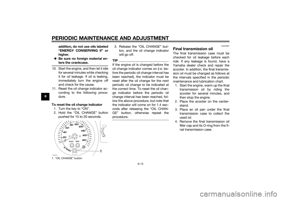
To reset the oil change indicator
1. Turn the key to “ON”.
2. Hold the “OIL CHANGE” button
pushed for 15 to 20 seconds.3. Release the “OIL CHANGE” but-
ton, and the oil change indicator
will go off.
TIPIf the engine oil is changed before the
oil change indicator comes on (i.e. be-
fore the periodic oil change interval has
been reached), the indicator must be
reset after the oil change for the next
periodic oil change to be indicated at
the correct time. To reset the oil chan-
ge indicator before the periodic oil
change interval has been reached, fol-
low the above procedure, but note that
the indicator will come on for 1.4 sec-
GEŽ button, otherwise repeat the
procedure.
EAU20067
Final transmission oilThe final transmission case must be
checked for oil leakage before each
ride. If any leakage is found, have a
Yamaha dealer check and repair the
scooter. In addition, the final transmis-
sion oil must be changed as follows at
the intervals specified in the periodic
maintenance and lubrication chart.
1. Start the engine, warm up the final
transmission oil by riding the
scooter for several minutes, and
then stop the engine.
2. Place the scooter on the center-
stand.
3. Place an oil pan under the final
transmission case to collect the
used oil.
4. Remove the final transmission oil
filler cap and its O-ring from the fi-
nal transmission case.
1. “OIL CHANGE” buttonZAUM1051
OIL CHANGE
1
U1SDE1E0.book Page 15 Monday, September 23, 2013 3:55 PM
Page 73 of 92
PERIODIC MAINTENANCE AND ADJUSTMENT
6-30
6 burns. Avoid any contact with
skin, eyes or clothing and al-
ways shield your eyes when
working near batteries. In case
of contact, administer the fol-
lowing FIRST AID.
EXTERNAL: Flush with plenty
of water.
INTERNAL: Drink large quan-
tities of water or milk and im-
mediately call a physician.
EYES: Flush with water for 15
minutes and seek prompt
medical attention.
Batteries produce explosive hy-
drogen gas. Therefore, keep
sparks, flames, cigarettes, etc.,
away from the battery and pro-
vide sufficient ventilation when
charging it in an enclosed
space.
KEEP THIS AND ALL BATTER-
IES OUT OF THE REACH OF
CHILDREN.
To charge the battery
Have a Yamaha dealer charge the bat-
tery as soon as possible if it seems to
have discharged. Keep in mind that thebattery tends to discharge more quick-
ly if the vehicle is equipped with op-
tional electrical accessories.
NOTICE
ECA16522
To charge a VRLA (Valve Regulated
Lead Acid) battery, a special (con-
stant-voltage) battery charger is re-
quired. Using a conventional battery
charger will damage the battery.To store the battery
1. If the model will not be used for
more than one month, remove the
battery, fully charge it, and then
place it in a cool, dry place.
NOTICE: When removing the
battery, be sure the key is
turned to “OFF”, then discon-
nect the negative lead before
disconnecting the positive lead.
[ECA16303]
2. If the battery will be stored for
more than two months, check it at
least once a month and fully char-
ge it if necessary.
3. Fully charge the battery before
installation. NOTICE: When in-
stalling the battery, be sure thekey is turned to “OFF”, then
connect the positive lead before
connecting the negative lead.
[ECA16841]
NOTICE
ECA16531
Always keep the battery charged.
Storing a discharged battery can
cause permanent battery damage.
U1SDE1E0.book Page 30 Monday, September 23, 2013 3:55 PM
Page 75 of 92
PERIODIC MAINTENANCE AND ADJUSTMENT
6-32
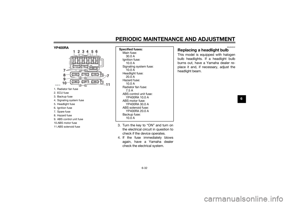
6 YP400RA
3. Turn the key to “ON” and turn on
the electrical circuit in question to
check if the device operates.
4. If the fuse immediately blows
again, have a Yamaha dealer
check the electrical system.
EAU34242
Replacing a headlight bulbThis model is equipped with halogen
bulb headlights. If a headlight bulb
burns out, have a Yamaha dealer re-
place it and, if necessary, adjust the
headlight beam.
1. Radiator fan fuse
2. ECU fuse
3. Backup fuse
4. Signaling system fuse
5. Headlight fuse
6. Ignition fuse
7. Spare fuse
8. Hazard fuse
9. ABS control unit fuse
10.ABS motor fuse
11.ABS solenoid fuseZAUM1129
10
10
10
20
30
30
7
7
11
1
2
3
4
56
20 1020
1010 1010
7.57.5
9
10
Specified fuses:
Main fuse:
30.0 A
Ignition fuse:
10.0 A
Signaling system fuse:
10.0 A
Headlight fuse:
20.0 A
Hazard fuse:
10.0 A
Radiator fan fuse:
7.5 A
ABS control unit fuse:
YP400RA 10.0 A
ABS motor fuse:
YP400RA 30.0 A
ABS solenoid fuse:
YP400RA 20.0 A
Backup fuse:
10.0 A
U1SDE1E0.book Page 32 Monday, September 23, 2013 3:55 PM