key YAMAHA XSR 900 2019 Owners Manual
[x] Cancel search | Manufacturer: YAMAHA, Model Year: 2019, Model line: XSR 900, Model: YAMAHA XSR 900 2019Pages: 102, PDF Size: 7.77 MB
Page 4 of 102

Important manual information
EAU10134
Particularly important information is distinguished in this manual by the following notations:
*Product and specifications are subject to change without notice.
This is the safety alert symbol. It is used to alert you to potential personal injury
hazards. Obey all safety messages that follow this symbol to avoid possible injury
or death.
A WARNING indicates a hazardous situation wh
ich, if not avoided, could result in
death or serious injury.
A NOTICE indicates special precautions that must be taken to avoid damage to the
vehicle or other property.
A TIP provides key information to make procedures easier or clearer.
WARNING
NOTICETIP
BAE-9-E0.book 1 ページ 2018年8月22日 水曜日 午後2時17分
Page 16 of 102
3-1
1
23
4
5
6
7
8
9
10
11
12
Instrument and control functions
EAU10979
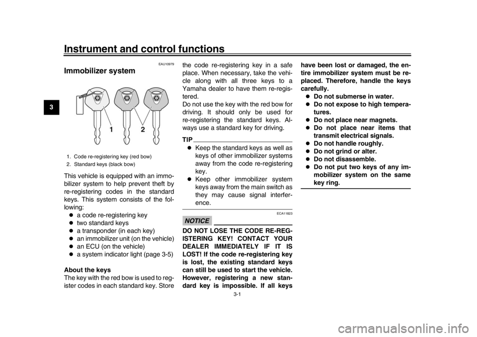
Immobilizer systemThis vehicle is equipped with an immo-
bilizer system to help prevent theft by
re-registering codes in the standard
keys. This system consists of the fol-
lowing:
a code re-registering key
two standard keys
a transponder (in each key)
an immobilizer unit (on the vehicle)
an ECU (on the vehicle)
a system indicator light (page 3-5)
About the keys
The key with the red bow is used to reg-
ister codes in each standard key. Store the code re-registering key in a safe
place. When necessary, take the vehi-
cle along with all three keys to a
Yamaha dealer to have them re-regis-
tered.
Do not use the key with the red bow for
driving. It should only be used for
re-registering the standard keys. Al-
ways use a standard key for driving.
TIP
Keep the standard keys as well as
keys of other immobilizer systems
away from the code re-registering
key.
Keep other immobilizer system
keys away from the main switch as
they may cause signal interfer-ence.
NOTICE
ECA11823
DO NOT LOSE THE CODE RE-REG-
ISTERING KEY! CONTACT YOUR
DEALER IMMEDIATELY IF IT IS
LOST! If the code re-registering key
is lost, the existing standard keys
can still be used to start the vehicle.
However, registering a new stan-
dard key is impossible. If all keyshave been lost or damaged, the en-
tire immobilizer system must be re-
placed. Therefore, handle the keys
carefully.
Do not submerse in water.
Do not expose to high tempera-
tures.
Do not place near magnets.
Do not place near items that
transmit electrical signals.
Do not handle roughly.
Do not grind or alter.
Do not disassemble.
Do not put two keys of any im-
mobilizer system on the samekey ring.
1. Code re-registering key (red bow)
2. Standard keys (black bow)
BAE-9-E0.book 1 ページ 2018年8月22日 水曜日 午後2時17分
Page 17 of 102
Instrument and control functions
3-2
1
234
5
6
7
8
9
10
11
12
EAU10474
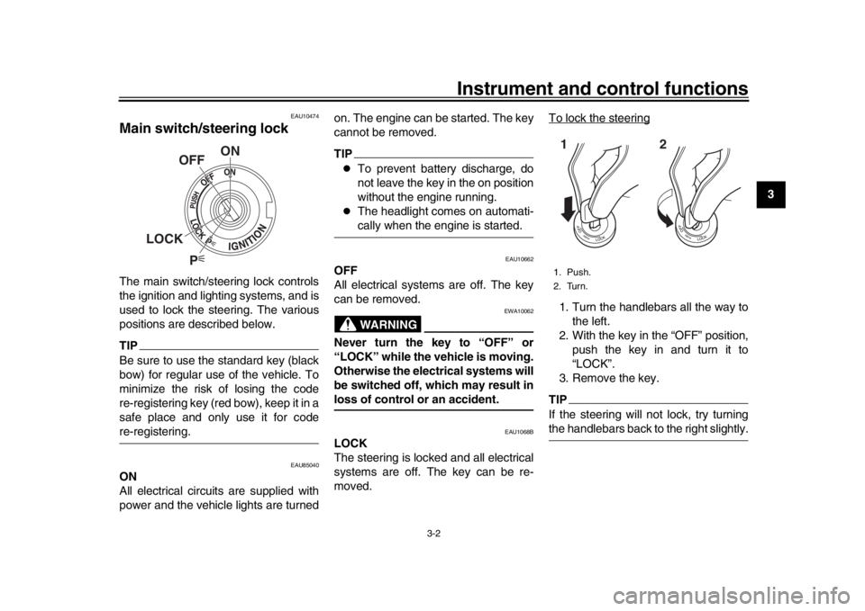
Main switch/steering lockThe main switch/steering lock controls
the ignition and lighting systems, and is
used to lock the steering. The various
positions are described below.TIPBe sure to use the standard key (black
bow) for regular use of the vehicle. To
minimize the risk of losing the code
re-registering key (red bow), keep it in a
safe place and only use it for codere-registering.
EAU85040
ON
All electrical circuits are supplied with
power and the vehicle lights are turned on. The engine can be started. The key
cannot be removed.
TIP
To prevent battery discharge, do
not leave the key in the on position
without the engine running.
The headlight comes on automati-cally when the engine is started.
EAU10662
OFF
All electrical systems are off. The key
can be removed.
WARNING
EWA10062
Never turn the key to “OFF” or
“LOCK” while the vehicle is moving.
Otherwise the electrical systems will
be switched off, which may result inloss of control or an accident.
EAU1068B
LOCK
The steering is locked and all electrical
systems are off. The key can be re-
moved.
To lock the steering
1. Turn the handlebars all the way to
the left.
2. With the key in the “OFF” position, push the key in and turn it to
“LOCK”.
3. Remove the key.TIPIf the steering will not lock, try turningthe handlebars back to the right slightly.
P
ON
OFF
LOCK
1. Push.
2. Turn.12
BAE-9-E0.book 2 ページ 2018年8月22日 水曜日 午後2時17分
Page 18 of 102
Instrument and control functions
3-3
1
23
4
5
6
7
8
9
10
11
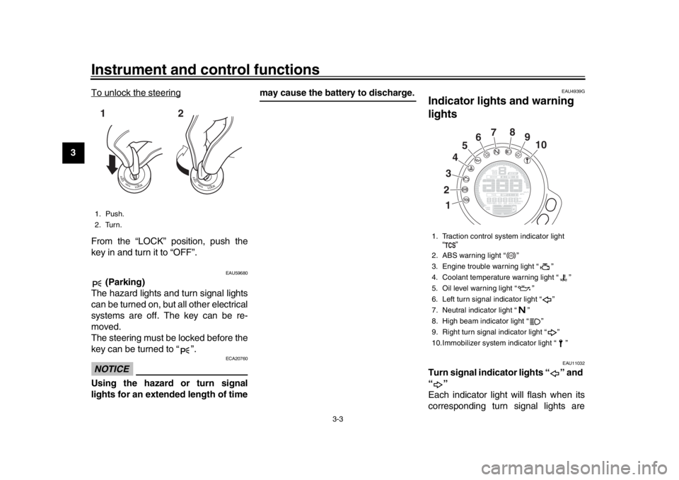
12 To unlock the steering
From the “LOCK” position, push the
key in and turn it to “OFF”.
EAU59680
(Parking)
The hazard lights and turn signal lights
can be turned on, but all other electrical
systems are off. The key can be re-
moved.
The steering must be locked before the
key can be turned to “ ”.NOTICE
ECA20760
Using the hazard or turn signal
lights for an extended length of time
may cause the battery to discharge.
EAU4939G
Indicator lights and warning
lights
EAU11032
Turn signal indicator lights “ ” and
“”
Each indicator light will flash when its
corresponding turn signal lights are
1. Push.
2. Turn.12
1. Traction control system indicator light “”
2. ABS warning light “ ”
3. Engine trouble warning light “ ”
4. Coolant temperature warning light “ ”
5. Oil level warning light “ ”
6. Left turn signal indicator light “ ”
7. Neutral indicator light “ ”
8. High beam indicator light “ ”
9. Right turn signal indicator light “ ”
10.Immobilizer system indicator light “ ”
2
13
4
5
6
7
8
9
10
ABS
BAE-9-E0.book 3 ページ 2018年8月22日 水曜日 午後2時17分
Page 20 of 102
Instrument and control functions
3-5
1
23
4
5
6
7
8
9
10
11
12
TIPIf the light does not come at all, or if the
light does not go off after traveling 10
km/h (6 mi/h), have a Yamaha dealercheck the vehicle.
WARNING
EWA16041
If the ABS warning light does not go
off after traveling at a speed of 10
km/h (6 mi/h) or higher, or if the
warning light comes on or flashes
while riding, the brake system re-
verts to conventional braking. If ei-
ther of the above occurs, or if the
warning light does not come on at
all, use extra caution to avoid possi-
ble wheel lock during emergency
braking. Have a Yamaha dealer
check the brake system and electri-cal circuits as soon as possible.
EAU78591
Traction control system indicator
light “TCS”
This indicator light will flash when trac-
tion control has engaged.
If the traction control system is turned
off, this indicator light will come on. (See page 3-17.)
TIPWhen the vehicle is turned on, the light
should come on for a few seconds and
then go off. If the light does not come
on, or if the light remains on, have aYamaha dealer check vehicle.
EAUM3621
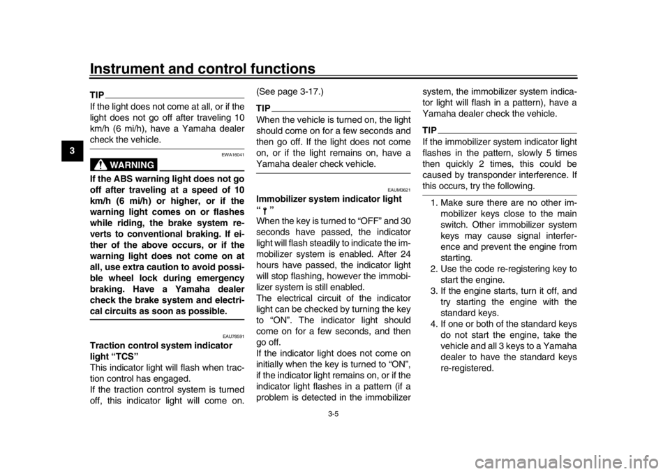
Immobilizer system indicator light
“”
When the key is turned to “OFF” and 30
seconds have passed, the indicator
light will flash steadil
y to indicate the im-
mobilizer system is enabled. After 24
hours have passed, the indicator light
will stop flashing, however the immobi-
lizer system is still enabled.
The electrical circuit of the indicator
light can be checked by turning the key
to “ON”. The indicator light should
come on for a few seconds, and then
go off.
If the indicator light does not come on
initially when the key is turned to “ON”,
if the indicator light remains on, or if the
indicator light flashes in a pattern (if a
problem is detected in the immobilizer system, the immobilizer system indica-
tor light will flash in a pattern), have a
Yamaha dealer check the vehicle.
TIPIf the immobilizer system indicator light
flashes in the pattern, slowly 5 times
then quickly 2 times, this could be
caused by transponder interference. Ifthis occurs, try the following.
1. Make sure there are no other im- mobilizer keys close to the main
switch. Other immobilizer system
keys may cause signal interfer-
ence and prevent the engine from
starting.
2. Use the code re-registering key to start the engine.
3. If the engine starts, turn it off, and try starting the engine with the
standard keys.
4. If one or both of the standard keys do not start the engine, take the
vehicle and all 3 keys to a Yamaha
dealer to have the standard keys
re-registered.
BAE-9-E0.book 5 ページ 2018年8月22日 水曜日 午後2時17分
Page 29 of 102
Instrument and control functions
3-14
1
234
5
6
7
8
9
10
11
12
of the traction control system and
the TCS settings.
EAU54212
Stop/Run/Start switch “ / / ”
To crank the engine with the starter, set
this switch to “ ”, and then push the
switch down towards “ ”. See page
5-1 for starting instructions prior to
starting the engine.
Set this switch to “ ” to stop the engine
in case of an emergency, such as when
the vehicle overturns or when the throt-
tle cable is stuck.
EAU12735
Hazard switch “ ”
With the key in the “ON” or “ ” posi-
tion, use this switch to turn on the haz-
ard lights (simultaneous flashing of all
turn signal lights).
The hazard lights are used in case of
an emergency or to warn other drivers
when your vehicle is stopped where it
might be a traffic hazard.NOTICE
ECA10062
Do not use the hazard lights for an
extended length of time with the en- gine not running, otherwise the bat-
tery may discharge.
EAU73321
Drive mode switch “MODE”
WARNING
EWA18440
Do not change the drive mode whilethe vehicle is moving.
With the throttle grip closed, press this
switch to change the drive mode (page
3-12) in the following order:
A
B STD ATIP
The current drive mode is shown in
the drive mode display (page 3-8).
The current drive mode is savedwhen the vehicle is turned off.
EAU12822
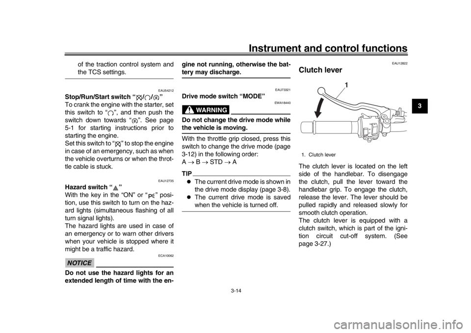
Clutch leverThe clutch lever is located on the left
side of the handlebar. To disengage
the clutch, pull the lever toward the
handlebar grip. To engage the clutch,
release the lever. The lever should be
pulled rapidly and released slowly for
smooth clutch operation.
The clutch lever is equipped with a
clutch switch, which is part of the igni-
tion circuit cut-off system. (See
page 3-27.)1. Clutch lever
1
BAE-9-E0.book 14 ページ 2018年8月22日 水曜日 午後2時17分
Page 31 of 102
Instrument and control functions
3-16
1
234
5
6
7
8
9
10
11
12
EAU12944
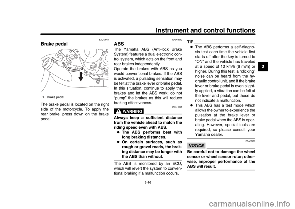
Brake pedalThe brake pedal is located on the right
side of the motorcycle. To apply the
rear brake, press down on the brake
pedal.
EAU63040
ABSThe Yamaha ABS (Anti-lock Brake
System) features a dual electronic con-
trol system, which acts on the front and
rear brakes independently.
Operate the brakes with ABS as you
would conventional br akes. If the ABS
is activated, a pulsating sensation may
be felt at the brake lever or brake pedal.
In this situation, continue to apply the
brakes and let the ABS work; do not
“pump” the brakes as this will reduce
braking effectiveness.
WARNING
EWA16051
Always keep a sufficient distance
from the vehicle ahead to match the
riding speed even with ABS.
The ABS performs best with
long braking distances.
On certain surfaces, such as
rough or gravel roads, the brak-
ing distance may be longer withthe ABS than without.
The ABS is monitored by an ECU,
which will revert the system to conven-
tional braking if a malfunction occurs.
TIP
The ABS performs a self-diagno-
sis test each time the vehicle first
starts off after the key is turned to
“ON” and the vehicle has traveled
at a speed of 10 km/h (6 mi/h) or
higher. During this test, a “clicking”
noise can be heard from the hy-
draulic control unit, and if the brake
lever or brake pedal is even slight-
ly applied, a vibration can be felt at
the lever and pedal, but these do
not indicate a malfunction.
This ABS has a test mode which
allows the owner to experience the
pulsation at the brake lever or
brake pedal when the ABS is oper-
ating. However, special tools are
required, so please consult yourYamaha dealer.
NOTICE
ECA20100
Be careful not to damage the wheel
sensor or wheel sensor rotor; other-
wise, improper performance of theABS will result.
1. Brake pedal
1
BAE-9-E0.book 16 ページ 2018年8月22日 水曜日 午後2時17分
Page 33 of 102
Instrument and control functions
3-18
1
234
5
6
7
8
9
10
11
12
or off only when the vehicle is
stopped.
When the key is turned to “ON”,
traction control is turned on and
set to TCS “1” or “2” (whichever
was last selected).
Turn the traction control system off
to help free the rear wheel if the ve-
hicle gets stuck in mud, sand, orother soft surfaces.
NOTICE
ECA16801
Use only the specified tires. (See
page 6-16.) Using different sized
tires will prevent the traction control
system from controlling tire rotationaccurately.
Resetting the traction control sys-
tem
The traction control system will auto-
matically disable when:
the front wheel or rear wheel
comes off the ground while riding.
excessive rear wheel spin is de-
tected while riding.
either wheel is rotated with the key
turned to “ON” (such as when per- forming maintenance).
If the traction control system is dis-
abled, both the “ ” indicator light and
the “ ” warning light will come on.
Should this occur, try resetting the sys-
tem as follows. 1. Stop the vehicle and turn the key to “OFF”.
2. Wait a few seconds and then turn key back “ON”.
3. The “ ” indicator light should turn off and the system be enabled.
TIPIf the “ ” indicator light remains on af-
ter resetting, the vehicle may still be rid-
den; however, have a Yamaha dealercheck the vehicle as soon as possible.
4. Have a Yamaha dealer check the vehicle and turn off the “ ” warn-
ing light.
EAU13076
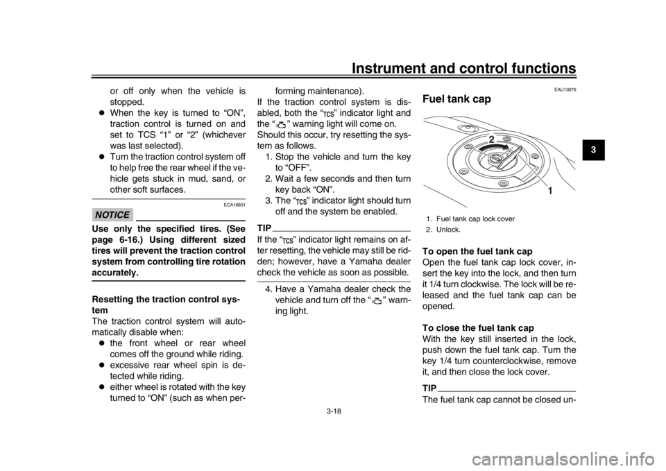
Fuel tank capTo open the fuel tank cap
Open the fuel tank cap lock cover, in-
sert the key into the lock, and then turn
it 1/4 turn clockwise. The lock will be re-
leased and the fuel tank cap can be
opened.
To close the fuel tank cap
With the key still inserted in the lock,
push down the fuel tank cap. Turn the
key 1/4 turn counterclockwise, remove
it, and then close the lock cover.TIPThe fuel tank cap cannot be closed un-1. Fuel tank cap lock cover
2. Unlock.
1
2
BAE-9-E0.book 18 ページ 2018年8月22日 水曜日 午後2時17分
Page 34 of 102
Instrument and control functions
3-19
1
23
4
5
6
7
8
9
10
11
12 less the key is in the lock. In addition,
the key cannot be removed if the cap is
not properly closed and locked.
WARNING
EWA11092
Make sure that the fuel tank cap is
properly closed after filling fuel.Leaking fuel is a fire hazard.
EAU13222
FuelMake sure there is sufficient gasoline in
the tank.
WARNING
EWA10882
Gasoline and gasoline vapors are
extremely flammable. To avoid fires
and explosions and to reduce the
risk of injury when refueling, followthese instructions.
1. Before refueling, turn off the en- gine and be sure that no one is sit-
ting on the vehicle. Never refuel
while smoking, or while in the vi-
cinity of sparks, open flames, or
other sources of ignition such as
the pilot lights of water heaters and
clothes dryers.
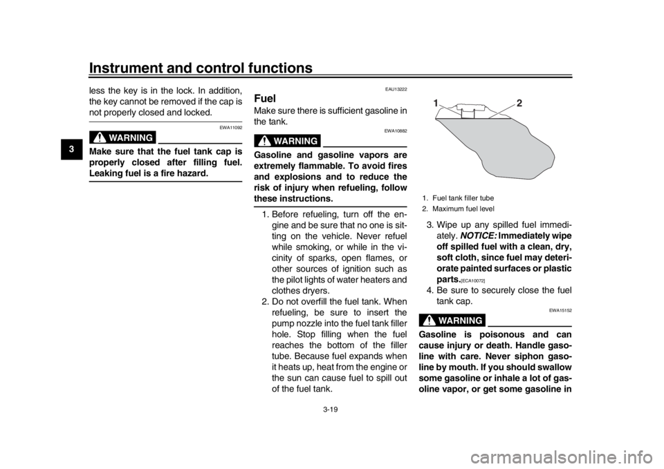
2. Do not overfill the fuel tank. When refueling, be sure to insert the
pump nozzle into the fuel tank filler
hole. Stop filling when the fuel
reaches the bottom of the filler
tube. Because fuel expands when
it heats up, heat from the engine or
the sun can cause fuel to spill out
of the fuel tank. 3. Wipe up any spilled fuel immedi-
ately. NOTICE: Immediately wipe
off spilled fuel with a clean, dry,
soft cloth, since fuel may deteri-
orate painted surfaces or plastic
parts.
[ECA10072]
4. Be sure to securely close the fuel tank cap.
WARNING
EWA15152
Gasoline is poisonous and can
cause injury or death. Handle gaso-
line with care. Never siphon gaso-
line by mouth. If you should swallow
some gasoline or inhale a lot of gas-
oline vapor, or get some gasoline in1. Fuel tank filler tube
2. Maximum fuel level
2
1
BAE-9-E0.book 19 ページ 2018年8月22日 水曜日 午後2時17分
Page 37 of 102
Instrument and control functions
3-22
1
234
5
6
7
8
9
10
11
12
EAU57991
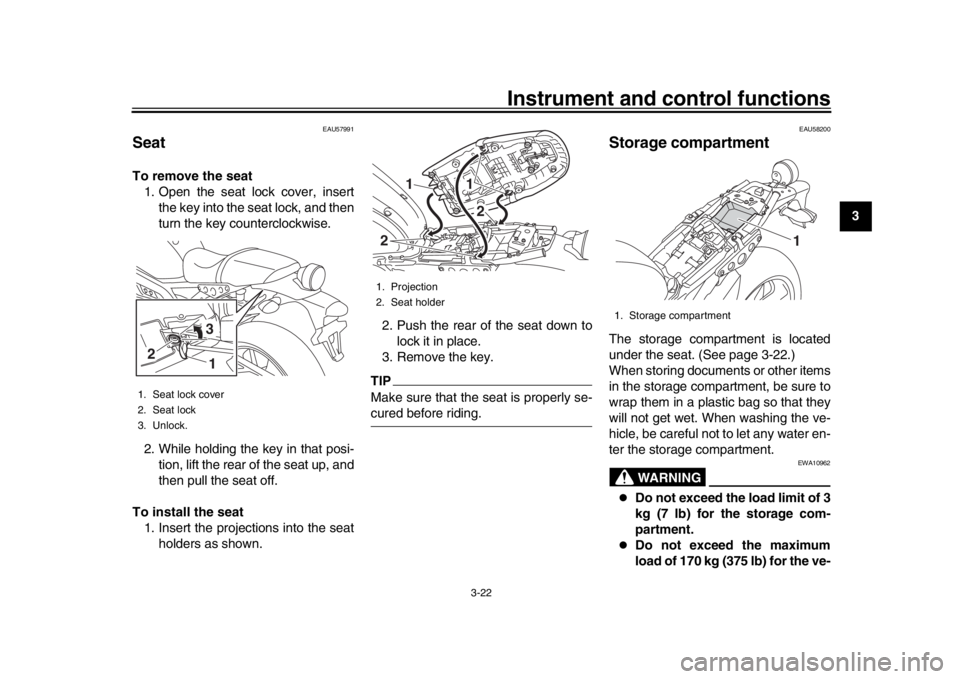
SeatTo remove the seat 1. Open the seat lock cover, insert the key into the seat lock, and then
turn the key counterclockwise.
2. While holding the key in that posi- tion, lift the rear of the seat up, and
then pull the seat off.
To install the seat 1. Insert the projections into the seat holders as shown. 2. Push the rear of the seat down to
lock it in place.
3. Remove the key.
TIPMake sure that the seat is properly se-cured before riding.
EAU58200
Storage compartmentThe storage compartment is located
under the seat. (See page 3-22.)
When storing documents or other items
in the storage compartment, be sure to
wrap them in a plastic bag so that they
will not get wet. When washing the ve-
hicle, be careful not to let any water en-
ter the storage compartment.
WARNING
EWA10962
Do not exceed the load limit of 3
kg (7 lb) for the storage com-
partment.
Do not exceed the maximum
load of 170 kg (375 lb) for the ve-
1. Seat lock cover
2. Seat lock
3. Unlock.2
31
1. Projection
2. Seat holder
11
2
2
1. Storage compartment
1
BAE-9-E0.book 22 ページ 2018年8月22日 水曜日 午後2時17分