parking YAMAHA XT1200ZE 2015 Owners Manual
[x] Cancel search | Manufacturer: YAMAHA, Model Year: 2015, Model line: XT1200ZE, Model: YAMAHA XT1200ZE 2015Pages: 118, PDF Size: 3.13 MB
Page 6 of 118
TABLE OF CONTENTSSAFETY INFORMATION.................. 1-1
DESCRIPTION .................................. 2-1
Left view ......................................... 2-1
Right view ....................................... 2-2
Controls and instruments ............... 2-3
INSTRUMENT AND CONTROL
FUNCTIONS ...................................... 3-1
Immobilizer system......................... 3-1
Main switch/steering lock............... 3-2
Indicator lights and warning lights............................................ 3-4
Cruise control system..................... 3-7
Multi-function meter unit .............. 3-10
D-mode (drive mode).................... 3-24
Handlebar switches ...................... 3-24
Clutch lever .................................. 3-26
Shift pedal .................................... 3-27
Brake lever.................................... 3-27
Brake pedal .................................. 3-28
ABS .............................................. 3-28
Traction control system ................ 3-29
Fuel tank cap ................................ 3-31
Fuel ............................................... 3-32
Fuel tank breather hose and
overflow hose ............................ 3-33
Catalytic converter ....................... 3-33
Rider seat ..................................... 3-34
Adjusting the rider seat height...... 3-35
Windshield .................................... 3-36 Adjusting the front and rear
suspension ................................ 3-37
Carriers.......................................... 3-42
Luggage strap holders .................. 3-42
Sidestand ...................................... 3-43
Ignition circuit cut-off system ....... 3-43
Auxiliary DC jack ........................... 3-45
FOR YOUR SAFETY –
PRE-OPERATION CHECKS ............. 4-1
OPERATION AND IMPORTANT
RIDING POINTS ................................ 5-1
Starting the engine .......................... 5-1
Shifting ............................................ 5-2
Tips for reducing fuel consumption ................................ 5-3
Engine break-in ............................... 5-3
Parking ............................................ 5-4
PERIODIC MAINTENANCE AND
ADJUSTMENT ................................... 6-1
Owner’s tool kit ............................... 6-2
Periodic maintenance chart for the
emission control system .............. 6-3
General maintenance and
lubrication chart ........................... 6-4
Removing and installing cowlings... 6-8
Checking the spark plugs ............. 6-10
Engine oil and oil filter cartridge.... 6-11
Final gear oil .................................. 6-14 Coolant ......................................... 6-15
Air filter element ............................ 6-17
Checking the engine idling
speed ........................................ 6-17
Checking the throttle grip free
play ............................................ 6-17
Valve clearance............................. 6-18
Tires .............................................. 6-18
Spoke wheels ............................... 6-20
Clutch lever................................... 6-21
Checking the brake lever free play ............................................ 6-21
Brake light switches ..................... 6-22
Checking the front and rear brake pads .......................................... 6-22
Checking the brake fluid level ...... 6-23
Changing the brake and clutch fluids .......................................... 6-24
Checking and lubricating the throttle grip and cable ............... 6-24
Checking and lubricating the brake and shift pedals............... 6-25
Checking and lubricating the
brake and clutch levers ............. 6-25
Checking and lubricating the centerstand and sidestand........ 6-26
Lubricating the swingarm pivots......................................... 6-27
Checking the front fork ................. 6-27
Checking the steering................... 6-28
Checking the wheel bearings ....... 6-28U2KBE1E0.book Page 1 Monday, August 18, 2014 9:42 AM
Page 42 of 118

INSTRUMENT AND CONTROL FUNCTIONS
3-27
3
EAU12872
Shift pedalThe shift pedal is located on the left
side of the motorcycle and is used in
combination with the clutch lever when
shifting the gears of the 6-speed con-
stant-mesh transmission equipped on
this motorcycle.
EAU49518
Brake leverThe brake lever is located on the right
side of the handlebar. To apply the
front brake, pull the lever toward the
throttle grip.
This model is equipped with a unified
brake system.
When pulling the brake lever, the front
brake and a portion of the rear brake
are applied. For full braking perfor-
mance, apply both the brake lever and
the brake pedal simultaneously.
The unified brake system is monitored
by an ECU, which disables unified
braking and resumes conventional
braking if a malfunction occurs.TIP Resistance and vibration may be
felt in the brake pedal while the
front brake is being applied and
the unified brake system is en-
abled, but this does not indicate a
malfunction.
The unified brake system does not
function until the vehicle starts
moving.
After coming to a stop while ap-
plying the brake lever, the unified
brake system is still enabled. As
further squeezing of the brake le-
ver will not increase the braking
power of the rear brake, apply the
rear brake should further braking
power be necessary (such as
when parking on a slope).
The unified brake system disables
after the brake lever is released.
The brake system then reverts to
the conventional type.
When the vehicle starts moving,
the unified brake system is re-en-
abled.
The unified brake system does not
function when the brake pedal is
applied alone or before the brake
lever is applied.
The brake lever is equipped with a
brake lever position adjusting dial. To
adjust the distance between the brake
lever and the throttle grip, turn the ad-
justing dial while holding the lever
pushed away from the throttle grip.
1. Shift pedal
1
U2KBE1E0.book Page 27 Monday, August 18, 2014 9:42 AM
Page 66 of 118

OPERATION AND IMPORTANT RIDING POINTS
5-4
51000–1600 km (600–1000 mi)
Avoid prolonged operation above 4700
r/min.
1600 km (1000 mi) an
d b eyon d
The vehicle can now be operated nor-
mally.
NOTICE
ECA20190
Keep the en gine spee d out of
the tachometer hi gh-rpm zone.
If any en gine trou ble shoul d oc-
cur durin g the eng ine break-in
period , imme diately have a
Yamaha dealer check the vehi-
cle.
EAU17214
Parkin gWhen parking, stop the engine, and
then remove the key from the main
switch.
WARNING
EWA10312
Since the en gine an d exhaust
system can become very hot,
park in a place where pe destri-
ans or chil dren are not likely to
touch them and b e burne d.
Do not park on a slope or on soft
groun d, otherwise the vehicle
may overturn, increasin g the
risk of a fuel leak an d fire.
Do not park near grass or other
flammab le materials which
mi ght catch fire.
U2KBE1E0.book Page 4 Monday, August 18, 2014 9:42 AM
Page 96 of 118
PERIODIC MAINTENANCE AND ADJUSTMENT
6-30
6
EAU58961
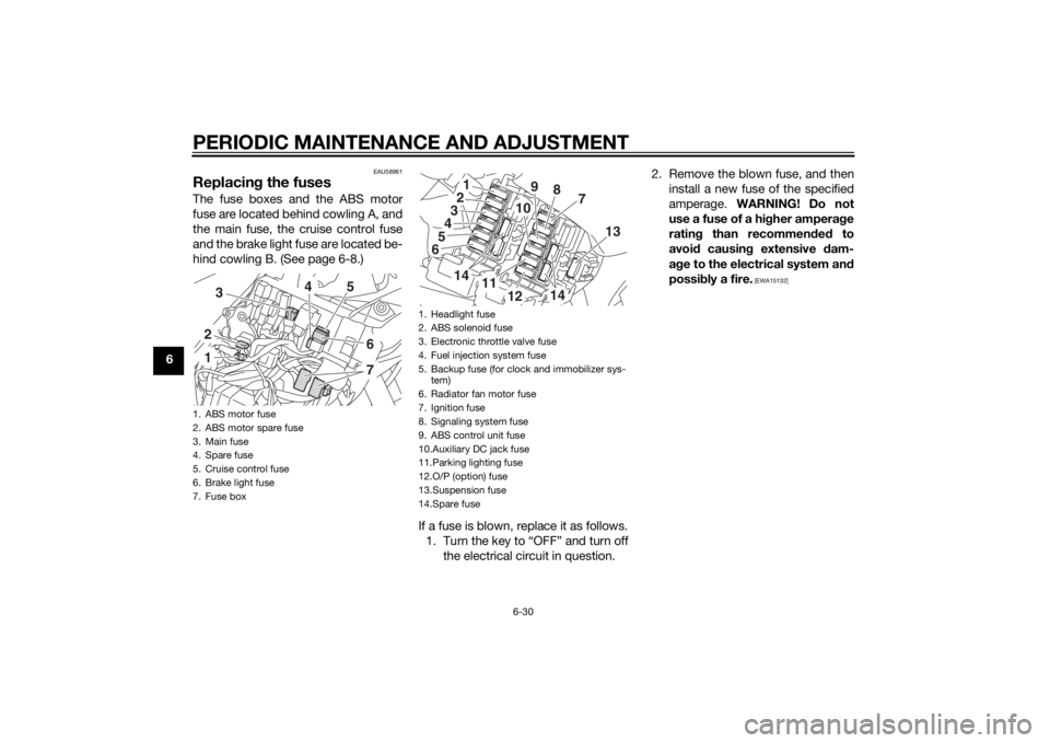
Replacing the fusesThe fuse boxes and the ABS motor
fuse are located behind cowling A, and
the main fuse, the cruise control fuse
and the brake light fuse are located be-
hind cowling B. (See page 6-8.)
If a fuse is blown, replace it as follows.1. Turn the key to “OFF” and turn off the electrical circuit in question. 2. Remove the blown fuse, and then
install a new fuse of the specified
amperage. WARNING! Do not
use a fuse of a hi gher ampera ge
ratin g than recommen ded to
avoi d causin g extensive d am-
a g e to the electrical system an d
possi bly a fire.
[EWA15132]
1. ABS motor fuse
2. ABS motor spare fuse
3. Main fuse
4. Spare fuse
5. Cruise control fuse
6. Brake light fuse
7. Fuse box123
5
67
4
1. Headlight fuse
2. ABS solenoid fuse
3. Electronic throttle valve fuse
4. Fuel injection system fuse
5. Backup fuse (for clock and immobilizer sys-
tem)
6. Radiator fan motor fuse
7. Ignition fuse
8. Signaling system fuse
9. ABS control unit fuse
10.Auxiliary DC jack fuse
11.Parking lighting fuse
12.O/P (option) fuse
13.Suspension fuse
14.Spare fuse
13456
2
7
8
9
10
14
13
11
12
14
U2KBE1E0.book Page 30 Monday, August 18, 2014 9:42 AM
Page 97 of 118
PERIODIC MAINTENANCE AND ADJUSTMENT
6-31
6
3. Turn the key to “ON” and turn on
the electrical circuit in question to
check if the device operates.
4. If the fuse immediately blows again, have a Yamaha dealer
check the electrical system.
EAU39014
Replacin g a hea dlig ht bul bThis model is equipped with halogen
bulb headlights. If a headlight bulb
burns out, replace it as follows.NOTICE
ECA10651
Take care not to d amage the follow-
in g parts:
Hea dlig ht bul b
Do not touch the glass part of
the hea dlig ht bul b to keep it free
from oil, otherwise the transpar-
ency of the glass, the luminosity
of the bul b, an d the bul b life will
b e a dversely affected . Thor-
ou ghly clean off any dirt an d fin-
g erprints on the head lig ht bul b
usin g a cloth moistene d with al-
cohol or thinner.
Hea dlig ht lens
Do not affix any type of tinted
film or stickers to the hea dlig ht
lens.
Do not use a hea dlig ht bul b of a
watta ge hi gher than specified .
Specified fuses:
Main fuse:
50.0 A
Headlight fuse: 20.0 A
Brake light fuse: 1.0 A
Parking lighting fuse:
7.5 A
Signaling system fuse: 7.5 A
Ignition fuse: 20.0 A
Radiator fan motor fuse:
20.0 A
Backup fuse: 7.5 A
Electronic throttle valve fuse: 7.5 A
Fuel injection system fuse:
20.0 A
ABS solenoid fuse: 20.0 A
ABS control unit fuse: 7.5 A
ABS motor fuse:
30.0 A
Suspension fuse: 15.0 A
Cruise control fuse: 1.0 A
Auxiliary DC jack fuse:
3.0 A
O/P (option) fuse: 20.0 A
U2KBE1E0.book Page 31 Monday, August 18, 2014 9:42 AM
Page 108 of 118

MOTORCYCLE CARE AND STORAGE
7-4
7
EAU49592
StorageShort-term
Always store your motorcycle in a cool,
dry place and, if necessary, protect it
against dust with a porous cover. Be
sure the engine and the exhaust sys-
tem are cool before covering the mo-
torcycle.NOTICE
ECA10811
Storin g the motorcycle in a
poorly ventilate d room or cover-
in g it with a tarp, while it is still
wet, will allow water an d humi d-
ity to seep in an d cause rust.
To prevent corrosion, avoi d
d amp cellars, sta bles ( because
of the presence of ammonia)
an d areas where stron g chemi-
cals are stored .Long-term
Before storing your motorcycle for sev-
eral months: 1. Follow all the instructions in the “Care” section of this chapter. 2. Fill up the fuel tank and add fuel
stabilizer (if available) to prevent
the fuel tank from rusting and the
fuel from deteriorating.
3. Perform the following steps to protect the cylinders, piston rings,
etc. from corrosion.a. Remove the spark plug caps and spark plugs.
b. Pour a teaspoonful of engine oil into each spark plug bore.
c. Install the spark plug caps onto the spark plugs, and then
place the spark plugs on the
cylinder head so that the elec-
trodes are grounded. (This will
limit sparking during the next
step.)
d. Turn the engine over several times with the starter. (This will
coat the cylinder walls with oil.)
WARNING! To prevent d am-
a g e or injury from sparkin g,
make sure to groun d the
spark plu g electro des while
turnin g the en gine over.
[EWA10952]
e. Remove the spark plug caps
from the spark plugs, and then
install the spark plugs and the
spark plug caps.
4. Lubricate all control cables and the pivoting points of all levers and
pedals as well as of the side-
stand/centerstand.
5. Check and, if necessary, correct the tire air pressure, and then lift
the motorcycle so that both of its
wheels are off the ground. Alterna-
tively, turn the wheels a little every
month in order to prevent the tires
from becoming degraded in one
spot.
6. Cover the muffler outlet with a plastic bag to prevent moisture
from entering it.
7. Remove the battery and fully charge it. Store it in a cool, dry
place and charge it once a month.
Do not store the battery in an ex-
cessively cold or warm place [less
than 0 °C (30 °F) or more than 30
°C (90 °F)]. For more information
on storing the battery, see page
6-28.
U2KBE1E0.book Page 4 Monday, August 18, 2014 9:42 AM
Page 112 of 118

SPECIFICATIONS
8-3
8
Electrical system:Ignition system:TCI
Charging system:
AC magnetoBattery:Model:YTZ12S
Voltage, capacity:
12 V, 11.0 AhHea dlig ht:Bulb type:
Halogen bulbBul b volta ge, watta ge × quantity:Headlight:
12 V, 55.0 W × 2
Tail/brake light: LED
Front turn signal light:
LED
Rear turn signal light: LED
Auxiliary light: 12 V, 5.0 W × 2
License plate light:
12 V, 5.0 W × 1
Meter lighting: LED
Neutral indicator light: LED
High beam indicator light:
LED
Oil level warning light: LED Turn signal indicator light:
LED
Engine trouble warning light: LED
ABS warning light:
LED
Cruise control “SET” indicator light: LED
Cruise control “ON” indicator light: LED
Immobilizer system indicator light:
LED
Traction control system indicator/warning
light:
LED
Suspension warning light: LED
Fuses:Main fuse:
50.0 A
Headlight fuse: 20.0 A
Brake light fuse: 1.0 A
Signaling system fuse:
7.5 A
Ignition fuse: 20.0 A
Parking lighting fuse: 7.5 A
Radiator fan motor fuse:
20.0 A
Fuel injection system fuse: 20.0 A ABS control unit fuse:
7.5 A
ABS motor fuse: 30.0 A
ABS solenoid fuse:
20.0 A
Suspension fuse: 15.0 A
Cruise control fuse: 1.0 A
Auxiliary DC jack fuse:
3.0 A
Backup fuse: 7.5 A
Electronic throttle valve fuse: 7.5 A
O/P (option) fuse:
20.0 A
U2KBE1E0.book Page 3 Monday, August 18, 2014 9:42 AM
Page 115 of 118

10-1
10
INDEX
AABS....................................................... 3-28
ABS warning light ................................... 3-5
Air filter element.................................... 6-17
Auxiliary DC jack .................................. 3-45
Auxiliary light bulb, replacing ............... 6-33BBattery .................................................. 6-28
Brake and clutch fluids, changing ........ 6-24
Brake and clutch levers, checking and lubricating........................................... 6-25
Brake and shift pedals, checking and
lubricating........................................... 6-25
Brake fluid level, checking.................... 6-23
Brake lever............................................ 3-27
Brake lever free play, checking ............ 6-21
Brake light switches ............................. 6-22
Brake pedal .......................................... 3-28CCare ........................................................ 7-1
Carriers ................................................. 3-42
Catalytic converter ............................... 3-33
Centerstand and sidestand, checking
and lubricating ................................... 6-26
Clutch lever.................................. 3-26, 6-21
Coolant ................................................. 6-15
Cowlings, removing and installing.......... 6-8
Cruise control indicator lights................. 3-4
Cruise control switches ........................ 3-25
Cruise control system............................. 3-7DDimmer/Pass switch............................. 3-25
D-mode (drive mode)............................ 3-24
EElectronically adjustable suspension system warning light ............................ 3-6
Engine break-in ...................................... 5-3
Engine idling speed, checking ............. 6-17
Engine oil and oil filter cartridge........... 6-11
Engine serial number ............................. 9-1
Engine trouble warning light .................. 3-5FFinal gear oil ......................................... 6-14
Front and rear brake pads, checking ... 6-22
Front fork, checking ............................. 6-27
Fuel ...................................................... 3-32
Fuel consumption, tips for reducing ...... 5-3
Fuel tank breather hose and overflow
hose ................................................... 3-33
Fuel tank cap........................................ 3-31
Fuses, replacing ................................... 6-30HHandlebar switches ............................. 3-24
Hazard switch ...................................... 3-25
Headlight bulb, replacing ..................... 6-31
High beam indicator light ....................... 3-4
Horn switch .......................................... 3-25IIdentification numbers ........................... 9-1
Ignition circuit cut-off system .............. 3-43
Immobilizer system ................................ 3-1
Immobilizer system indicator light ......... 3-6
Indicator lights and warning lights ......... 3-4LLicense plate light bulb, replacing ....... 6-35
Luggage strap holders ......................... 3-42
MMain switch/steering lock ....................... 3-2
Maintenance and lubrication, periodic ... 6-4
Maintenance, emission control
system .................................................. 6-3
Matte color, caution................................ 7-1
Menu switch ......................................... 3-25
Model label ............................................. 9-1
Multi-function meter unit ...................... 3-10NNeutral indicator light ............................. 3-4OOil level warning light .............................. 3-4PParking.................................................... 5-4
Part locations.......................................... 2-1RRider seat.............................................. 3-34
Rider seat height, adjusting .................. 3-35SSafety information................................... 1-1
Select switch ........................................ 3-26
Shifting.................................................... 5-2
Shift pedal............................................. 3-27
Sidestand.............................................. 3-43
Spark plugs, checking .......................... 6-10
Specifications ......................................... 8-1
Start/Engine stop switch ...................... 3-25
Starting the engine ................................. 5-1
Steering, checking ................................ 6-28
Storage ................................................... 7-4
Suspension, adjusting the front and
rear ..................................................... 3-37
Swingarm pivots, lubricating ................ 6-27
U2KBE1E0.book Page 1 Monday, August 18, 2014 9:42 AM