torque YAMAHA XT1200ZE 2017 Owners Manual
[x] Cancel search | Manufacturer: YAMAHA, Model Year: 2017, Model line: XT1200ZE, Model: YAMAHA XT1200ZE 2017Pages: 122, PDF Size: 3.36 MB
Page 68 of 122
Periodic maintenance an d a djustment
6-2
6
EAU17303
Emission controls not only function to
ensure cleaner air, but are also vital to
proper engine operation and maximum
performance. In the following periodic
maintenance charts, the services relat-
ed to emissions control are grouped
separately. These services require
specialized data, knowledge, and
equipment. Maintenance, replace-
ment, or repair of the emission control
devices and systems may be per-
formed by any repair establishment or
individual that is certified (if applicable).
Yamaha dealers are trained and equipped to perform these particular
services.
EAU49563
Owner’s tool kit
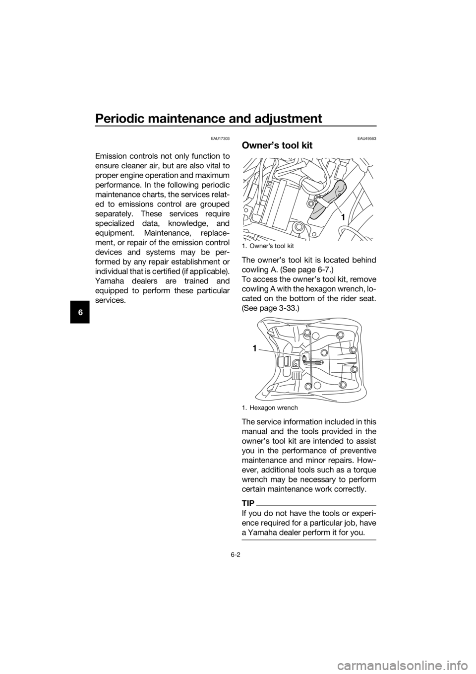
The owner’s tool kit is located behind
cowling A. (See page 6-7.)
To access the owner’s tool kit, remove
cowling A with the hexagon wrench, lo-
cated on the bottom of the rider seat.
(See page 3-33.)
The service information included in this
manual and the tools provided in the
owner’s tool kit are intended to assist
you in the performance of preventive
maintenance and minor repairs. How-
ever, additional tools such as a torque
wrench may be necessary to perform
certain maintenance work correctly.
TIP
If you do not have the tools or experi-
ence required for a particular job, have
a Yamaha dealer perform it for you.
1. Owner’s tool kit
1. Hexagon wrench
1
1
UBP9E0E0.book Page 2 Wedne sday, February 8, 2017 8:34 AM
Page 75 of 122
Periodic maintenance an d a djustment
6-9
6
EAU19653
Checkin g the spark plu gs
The spark plugs are important engine
components, which should be
checked periodically, preferably by a
Yamaha dealer. Since heat and depos- its will cause any spark plug to slowly
erode, they should be removed and
checked in accordance with the peri-
odic maintenance and lubrication
chart. In addition, the condition of the
spark plugs can reveal the condition of
the engine.
The porcelain insulator around the
center electrode of each spark plug
should be a medium-to-light tan (the
ideal color when the vehicle is ridden
normally), and all spark plugs installed
in the engine should have the same
color. If any spark plug shows a dis-
tinctly different color, the engine could
be operating improperly. Do not at-
tempt to diagnose such problems
yourself. Instead, have a Yamaha deal-
er check the vehicle.
If a spark plug shows signs of elec-
trode erosion and excessive carbon or
other deposits, it should be replaced.
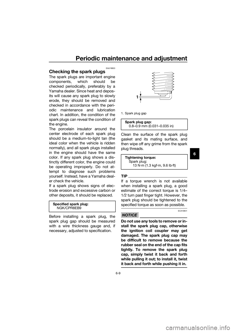
Before installing a spark plug, the
spark plug gap should be measured
with a wire thickness gauge and, if
necessary, adjusted to specification. Clean the surface of the spark plug
gasket and its mating surface, and
then wipe off any grime from the spark
plug threads.
TIP
If a torque wrench is not available
when installing a spark plug, a good
estimate of the correct torque is 1/4–
1/2 turn past finger tight. However, the
spark plug should be tightened to the
specified torque as soon as possible.
NOTICE
ECA10841
Do not use any tools to remove or in-
stall the spark plu
g cap, otherwise
the i gnition coil coupler may get
d amag ed . The spark plu g cap may
b e difficult to remove because the
ru bber seal on the en d of the cap fits
ti g htly. To remove the spark plu g
cap, simply twist it b ack and forth
while pullin g it out; to install it, twist
it back an d forth while pushin g it in.
Specified spark plu g:
NGK/CPR8EB9
1. Spark plug gap
Spark plu g g ap:
0.8–0.9 mm (0.031–0.035 in)
Ti ghtenin g torque:
Spark plug: 13 N·m (1.3 kgf·m, 9.6 lb·ft)
UBP9E0E0.book Page 9 Wedne sday, February 8, 2017 8:34 AM
Page 78 of 122
Periodic maintenance an d a djustment
6-12
6
TIP
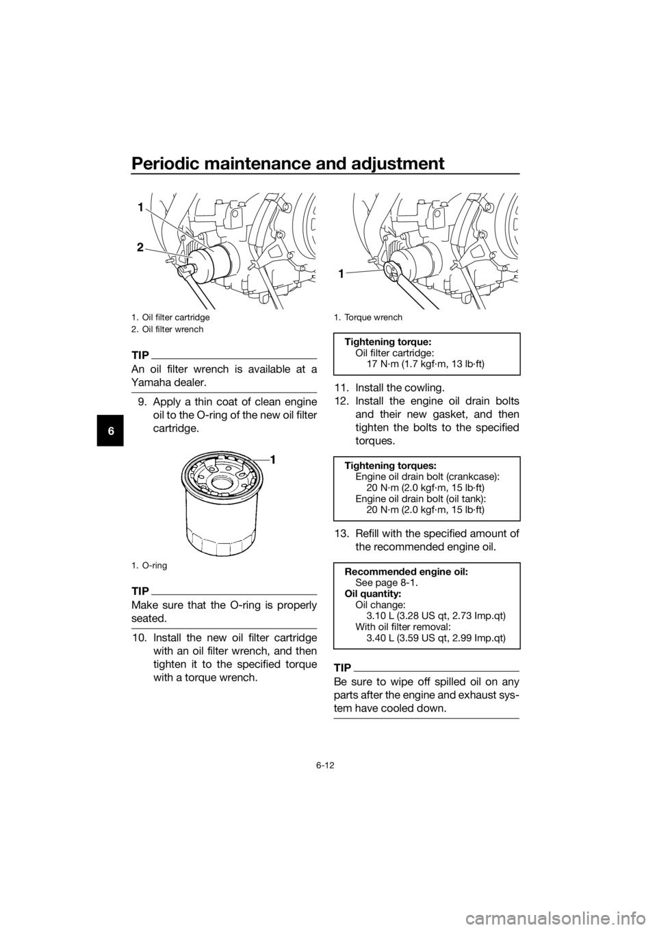
An oil filter wrench is available at a
Yamaha dealer.
9. Apply a thin coat of clean engine oil to the O-ring of the new oil filter
cartridge.
TIP
Make sure that the O-ring is properly
seated.
10. Install the new oil filter cartridge with an oil filter wrench, and then
tighten it to the specified torque
with a torque wrench. 11. Install the cowling.
12. Install the engine oil drain bolts
and their new gasket, and then
tighten the bolts to the specified
torques.
13. Refill with the specified amount of the recommended engine oil.
TIP
Be sure to wipe off spilled oil on any
parts after the engine and exhaust sys-
tem have cooled down.
1. Oil filter cartridge
2. Oil filter wrench
1. O-ring
2
1
1. Torque wrench
Tightening torque:
Oil filter cartridge: 17 N·m (1.7 kgf·m, 13 lb·ft)
Ti ghtening torques:
Engine oil drain bolt (crankcase):
20 N·m (2.0 kgf·m, 15 lb·ft)
Engine oil drain bolt (oil tank): 20 N·m (2.0 kgf·m, 15 lb·ft)
Recommen ded en gine oil:
See page 8-1.
Oil quantity: Oil change:3.10 L (3.28 US qt, 2.73 Imp.qt)
With oil filter removal: 3.40 L (3.59 US qt, 2.99 Imp.qt)
1
UBP9E0E0.book Page 12 Wednesday, February 8, 2017 8:34 AM
Page 80 of 122
Periodic maintenance an d a djustment
6-14
6
EAU20017
Final g ear oil
The final gear case must be checked
for oil leakage before each ride. If any
leakage is found, have a Yamaha deal-
er check and repair the vehicle. In ad-
dition, the final gear oil level must be
checked and the oil changed as fol-
lows at the intervals specified in the
periodic maintenance and lubrication
chart.
WARNING
EWA10371
Make sure that no forei gn mate-
rial enters the final g ear case.
Make sure that no oil g ets on
the tire or wheel.
To check the final gear oil level
1. Place the vehicle on the center- stand.
TIP
Make sure that the vehicle is posi-
tioned straight up when checking the
oil level. A slight tilt to the side can re-
sult in a false reading.
2. Remove the final gear oil filler boltand its gasket, and then check the
oil level in the final gear case.
TIP
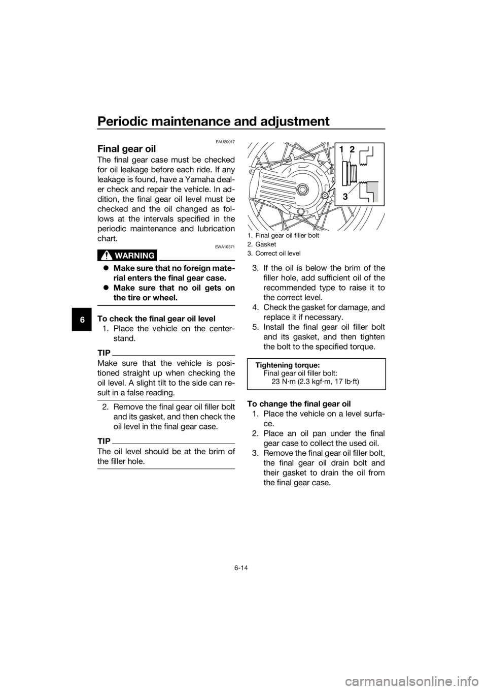
The oil level should be at the brim of
the filler hole.
3. If the oil is below the brim of thefiller hole, add sufficient oil of the
recommended type to raise it to
the correct level.
4. Check the gasket for damage, and replace it if necessary.
5. Install the final gear oil filler bolt and its gasket, and then tighten
the bolt to the specified torque.
To chan ge the final gear oil
1. Place the vehicle on a level surfa- ce.
2. Place an oil pan under the final gear case to collect the used oil.
3. Remove the final gear oil filler bolt, the final gear oil drain bolt and
their gasket to drain the oil from
the final gear case.
1. Final gear oil filler bolt
2. Gasket
3. Correct oil level
Tightening torque:
Final gear oil filler bolt:
23 N·m (2.3 kgf·m, 17 lb·ft)
12
3
UBP9E0E0.book Page 14 Wednesday, February 8, 2017 8:34 AM
Page 81 of 122
Periodic maintenance an d a djustment
6-15
6
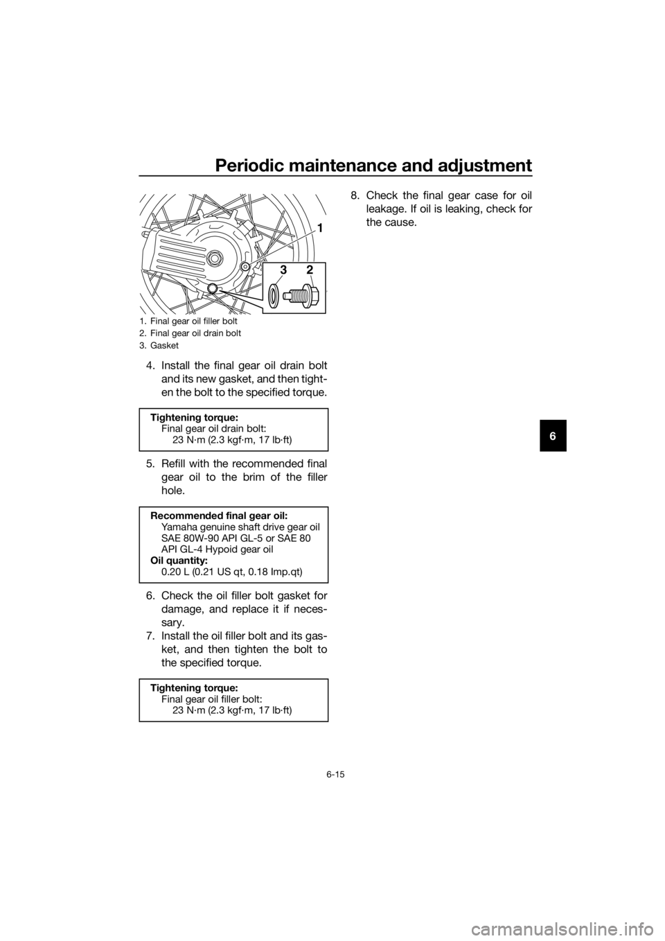
4. Install the final gear oil drain bolt
and its new gasket, and then tight-
en the bolt to the specified torque.
5. Refill with the recommended final gear oil to the brim of the filler
hole.
6. Check the oil filler bolt gasket for damage, and replace it if neces-
sary.
7. Install the oil filler bolt and its gas- ket, and then tighten the bolt to
the specified torque. 8. Check the final gear case for oil
leakage. If oil is leaking, check for
the cause.
1. Final gear oil filler bolt
2. Final gear oil drain bolt
3. Gasket
Tightening torque:
Final gear oil drain bolt:
23 N·m (2.3 kgf·m, 17 lb·ft)
Recommen ded final gear oil:
Yamaha genuine shaft drive gear oil
SAE 80W-90 API GL-5 or SAE 80
API GL-4 Hypoid gear oil
Oil quantity: 0.20 L (0.21 US qt, 0.18 Imp.qt)
Ti ghtening torque:
Final gear oil filler bolt: 23 N·m (2.3 kgf·m, 17 lb·ft)
23
1
UBP9E0E0.book Page 15 Wednesday, February 8, 2017 8:34 AM
Page 102 of 122
Periodic maintenance an d a djustment
6-36
6
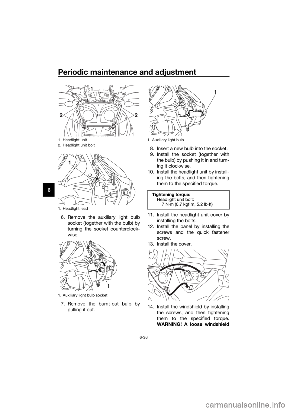
6. Remove the auxiliary light bulbsocket (together with the bulb) by
turning the socket counterclock-
wise.
7. Remove the burnt-out bulb by pulling it out. 8. Insert a new bulb into the socket.
9. Install the socket (together with
the bulb) by pushing it in and turn-
ing it clockwise.
10. Install the headlight unit by install- ing the bolts, and then tightening
them to the specified torque.
11. Install the headlight unit cover by installing the bolts.
12. Install the panel by installing the screws and the quick fastener
screw.
13. Install the cover.
14. Install the windshield by installing the screws, and then tightening
them to the specified torque.
WARNING! A loose win dshield
1. Headlight unit
2. Headlight unit bolt
1. Headlight lead
1. Auxiliary light bulb socket
1
2
2
1
1
1. Auxiliary light bulb
Tightening torque:
Headlight unit bolt: 7 N·m (0.7 kgf·m, 5.2 lb·ft)
1
UBP9E0E0.book Page 36 Wednesday, February 8, 2017 8:34 AM
Page 103 of 122
![YAMAHA XT1200ZE 2017 Owners Manual Periodic maintenance an d a djustment
6-37
6
coul
d cause an acci dent. Be
sure to tig hten the screws to the
specified torque.
[EWA15511] EAU70570
Turn si
gnal li ght and b rake/tail
lig ht
This YAMAHA XT1200ZE 2017 Owners Manual Periodic maintenance an d a djustment
6-37
6
coul
d cause an acci dent. Be
sure to tig hten the screws to the
specified torque.
[EWA15511] EAU70570
Turn si
gnal li ght and b rake/tail
lig ht
This](/img/51/53169/w960_53169-102.png)
Periodic maintenance an d a djustment
6-37
6
coul
d cause an acci dent. Be
sure to tig hten the screws to the
specified torque.
[EWA15511] EAU70570
Turn si
gnal li ght and b rake/tail
lig ht
This model is equipped with LED-type
turn signal lights and an LED-type
brake/tail light.
If a turn signal light or the brake/tail
light does not come on, have a
Yamaha dealer check it.
Ti ghtening torque:
Windshield screw: 0.5 N·m (0.05 kgf·m, 0.37 lb·ft)
UBP9E0E0.book Page 37 Wednesday, February 8, 2017 8:34 AM