ECU YAMAHA XT500E 2002 Owners Manual
[x] Cancel search | Manufacturer: YAMAHA, Model Year: 2002, Model line: XT500E, Model: YAMAHA XT500E 2002Pages: 100, PDF Size: 2.1 MB
Page 23 of 100

3-9
EAU04038
Starter (choke) knob“1”Starter (choke) knobStarting a cold engine requires a rich-
er air-fuel mixture, which is supplied
by the starter (choke).
Move the knob in direction ato turn
on the starter (choke).
Move the knob in direction bto turn
off the starter (choke).INSTRUMENT AND CONTROL FUNCTIONS
3
1
b
a
1. Starter (choke) knob “1”
To install the seat
1. Insert the projections on the front
of the seat into the seat holders
as shown.
2. Place the seat in the original
position, and then tighten the
bolts.NOTE:
Make sure that the seat is properly
secured before riding.
1
2
1. Projection (
×2)
2. Seat holder (×2)
EAU00240
SeatSeatTo remove the seat
Remove the bolts, and then pull the
seat off.
1
1. Bolt (×2)
4PT-E7 (English) 6/29/01 9:13 AM Page 22
Page 49 of 100

6-11
PERIODIC MAINTENANCE AND MINOR REPAIR
6
EC000000
cCDo not operate the motorcycle
until you know that the engine oil
level is sufficient.
EW000065
wNever remove the engine oil tank
cap after high-speed operation,
otherwise hot engine oil could
spout out and cause damage or
injury. Always let the engine oil
cool down sufficiently before
removing the oil tank cap.5. If the engine oil is below the min-
imum level mark, add sufficient
oil of the recommended type to
raise it to the correct level.
6. Install the oil filler cap and the oil
filler cap cover.4. Check the washers for damage
and replace them if necessary.
NOTE:
Skip steps 5–8 if the oil filter element
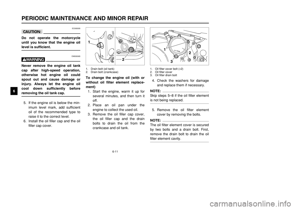
is not being replaced.5. Remove the oil filter element
cover by removing the bolts.NOTE:
The oil filter element cover is secured
by two bolts and a drain bolt. First,
remove the drain bolt to drain the oil
filter element cavity.
1
32
1. Oil filter cover bolt (×2)
2. Oil filter cover
3. Oil filter drain bolt
To change the engine oil (with or
without oil filter element replace-
ment)
1. Start the engine, warm it up for
several minutes, and then turn it
off.
2. Place an oil pan under the
engine to collect the used oil.
3. Remove the oil filler cap cover,
the oil filler cap and the drain
bolts to drain the oil from the
crankcase and oil tank.1. Drain bolt (oil tank)
2. Drain bolt (crankcase)1
2
4PT-E7 (English) 6/29/01 9:13 AM Page 48
Page 55 of 100

6-17
PERIODIC MAINTENANCE AND MINOR REPAIR
68 8
Adjust the suspension and tire
air pressure with regard to the
load.
8Check the tire condition and
air pressure before each ride.
EWA00012
wBecause loading has an enormous
impact on the handling, braking,
performance and safety character-
istics of your motorcycle, you
should keep the following precau-
tions in mind.
8NEVER OVERLOAD THE
MOTORCYCLE! Operation of
an overloaded motorcycle may
result in tire damage, loss of
control, or severe injury. Make
sure that the total weight of
rider, passenger, cargo, and
accessories does not exceed
the specified maximum load
for the vehicle.
8Do not carry along loosely
packed items, which can shift
during a ride.
8Securely pack the heaviest
items close to the center of the
motorcycle and distribute the
weight evenly on both sides.
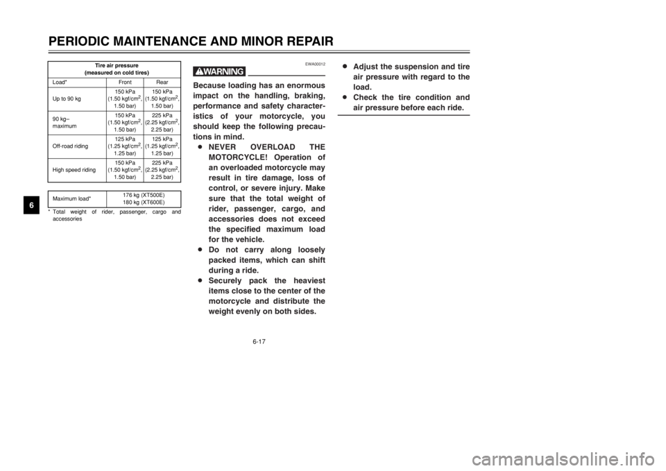
Tire air pressure
(measured on cold tires)
Load* Front Rear
Up to 90 kg150 kPa
(1.50 kgf/cm
2,
1.50 bar)150 kPa
(1.50 kgf/cm
2,
1.50 bar)
90 kg–
maximum150 kPa
(1.50 kgf/cm
2,
1.50 bar)225 kPa
(2.25 kgf/cm
2,
2.25 bar)
Off-road riding125 kPa
(1.25 kgf/cm
2,
1.25 bar)125 kPa
(1.25 kgf/cm
2,
1.25 bar)
High speed riding150 kPa
(1.50 kgf/cm
2,
1.50 bar)225 kPa
(2.25 kgf/cm
2,
2.25 bar)
Maximum load*176 kg (XT500E)
180 kg (XT600E)
* Total weight of rider, passenger, cargo and
accessories
4PT-E7 (English) 6/29/01 9:13 AM Page 54
Page 67 of 100

6-29
PERIODIC MAINTENANCE AND MINOR REPAIR
6
EAU00790
Lubricating the rear
suspensionRear suspension, lubricatingThe pivoting points of the rear sus-
pension must be lubricated at the
intervals specified in the periodic
maintenance and lubrication chart.
1
1
1. Grease nipple (×2)
To check the operation
1. Place the motorcycle on a level
surface and hold it in an upright
position.
2. While applying the front brake,
push down hard on the handle-
bars several times to check if the
front fork compresses and
rebounds smoothly.
EC000098
cCIf any damage is found or the front
fork does not operate smoothly,
have a Yamaha dealer check or
repair it.
EAU02939
Checking the front forkFront fork, checkingThe condition and operation of the
front fork must be checked as follows
at the intervals specified in the peri-
odic maintenance and lubrication
chart.
To check the condition
EW000115
wSecurely support the motorcycle
so that there is no danger of it
falling over.Check the inner tubes for scratches,
damage and excessive oil leakage.
Recommended lubricant:
Molybdenum disulfide grease
4PT-E7 (English) 6/29/01 9:13 AM Page 66
Page 68 of 100

6-30
PERIODIC MAINTENANCE AND MINOR REPAIR
6
EAU00794
Checking the steeringSteering, checkingWorn or loose steering bearings may
cause danger. Therefore, the opera-
tion of the steering must be checked
as follows at the intervals specified in
the periodic maintenance and lubrica-
tion chart.
1. Place a stand under the engine
to raise the front wheel off the
ground.
EW000115
wSecurely support the motorcycle
so that there is no danger of it
falling over.
EAU01144
Checking the wheel bearingsWheel bearings, checkingThe front and rear wheel bearings
must be checked at the intervals
specified in the periodic maintenance
and lubrication chart. If there is play
in the wheel hub or if the wheel does
not turn smoothly, have a Yamaha
dealer check the wheel bearings.
2. Hold the lower ends of the front
fork legs and try to move them
forward and backward. If any
free play can be felt, have a
Yamaha dealer check or repair
the steering.
4PT-E7 (English) 6/29/01 9:13 AM Page 67
Page 72 of 100

6-34
PERIODIC MAINTENANCE AND MINOR REPAIR
6 4. Remove the headlight bulb hold-
er by turning it counterclockwise,
and then remove the defective
bulb.
EW000119
wHeadlight bulbs get very hot.
Therefore, keep flammable prod-
ucts away from a lit headlight bulb,
and do not touch the bulb until it
has cooled down.
1
1. Headlight bulb holder
6. Install the bulb cover, and then
connect the coupler and leads.
7. Install the headlight unit by
installing the bolts.
8. Install the cowling.
9. Have a Yamaha dealer adjust
the headlight beam if necessary.
5. Place a new bulb into position,
and then secure it with the bulb
holder.
EC000105
cCDo not touch the glass part of the
headlight bulb to keep it free from
oil, otherwise the transparency of
the glass, the luminosity of the
bulb, and the bulb life will be
adversely affected. Thoroughly
clean off any dirt and fingerprints
on the headlight bulb using a cloth
moistened with alcohol or thinner.
a
a. Do not touch this area.
4PT-E7 (English) 6/29/01 9:13 AM Page 71
Page 75 of 100

6-37
PERIODIC MAINTENANCE AND MINOR REPAIR
6
EAU00897
Front wheel RemovingTo remove the front wheel
EW000122
w8It is advisable to have a
Yamaha dealer service the
wheel.
8Securely support the motorcy-
cle so that there is no danger
of it falling over.1. Disconnect the speedometer
cable from the front wheel.
1
1. Speedometer cable
EAU03555
To install the front wheelInstalling1. Install the speedometer gear unit
into the wheel hub so that the
projections mesh with the slots.
2. Lift the wheel up between the
fork legs.
1
1. Speedometer gear unit
2. Loosen the wheel axle holder
nuts, then the wheel axle.
3. Lift the front wheel off the ground
according to the procedure on
page 6-36.
4. Pull the wheel axle out, and then
remove the wheel.
ECA00048
cCDo not apply the brake after the
wheel has been removed together
with the brake disc, otherwise the
brake pads will be forced shut.
1
2
1. Wheel axle holder nut (×4)
2. Wheel axle
4PT-E7 (English) 6/29/01 9:13 AM Page 74
Page 77 of 100

6-39
PERIODIC MAINTENANCE AND MINOR REPAIR
6
EAU04314
Rear wheelTo remove the rear wheel
EW000122
w8 8
It is advisable to have a
Yamaha dealer service the
wheel.
8Securely support the motorcy-
cle so that there is no danger
of it falling over.1. Remove the axle nut.
2. Loosen the brake caliper bracket
bolt.
2
1
1. Axle nut
2. Brake caliper bracket bolt
5. Turn the drive chain adjusting
plate on each side of the
swingarm fully in direction a.
1
a
1. Chain adjusting plate
3. Lift the rear wheel off the ground
according to the procedure on
page 6-36.
4. Remove the swingarm end bolts.
1
1
1. Swingarm end bolt (×2)
4PT-E7 (English) 6/29/01 9:13 AM Page 76