key YAMAHA XT660Z 2012 User Guide
[x] Cancel search | Manufacturer: YAMAHA, Model Year: 2012, Model line: XT660Z, Model: YAMAHA XT660Z 2012Pages: 100, PDF Size: 8.65 MB
Page 28 of 100

INSTRUMENT AND CONTROL FUNCTIONS
4-12
1
2
3
4
\f
6
7
8
\b
10
To close the fuel tank cap 1. Push the fuel tank cap \fnto pos\f- t\fon w\fth the key \fnse\bted \fn the
lock.
2. Tu\bn the key counte\bclockw\fse to the o\b\fg\fnal pos\ft\fon, \bemove \ft,
and then close the\p lock cove\b.
TIP
The fuel tank cap cannot be closed
unless the key \fs \fn the lock. In add\f-
t\fon, the key cannot be \bemoved \ff the
cap \fs not p\bope\bly closed and locked.
EWA11091
WARNING0
Make sure that the fuel tank cap is
properly closed after filling fuel.
Leaking fuel is a \4fire hazard.
EAU13221
Fuel
Make su\be the\be \fs suff\fc\fent gasol\fne
\fn the tank.
EWA10881
WARNING0
Gasoline and gasoline vapors are
extremely flammable. To avoid fires
and explosions and to reduce the
risk of injury when refueling, follow
these instructions.\4
1. Befo\be \befuel\fng, tu\bn off the en- g\fne and be su\be that no one \fs
s\ftt\fng on the veh\fcle. Neve\b \befuel
wh\fle smok\fng, o\b wh\fle \fn the
v\fc\fn\fty of spa\bks, open flames, o\b
othe\b sou\bces of \fgn\ft\fon such as
the p\flot l\fghts of wate\b heate\bs
and clothes d\bye\bs.
2. Do not ove\bf\fll the fuel tank. When \befuel\fng, be su\be to \fnse\bt the
pump nozzle \fnto the fuel tank
f\flle\b hole. Stop f\fll\fng when the fu-
el \beaches the bottom of the f\flle\b
tube. Because fuel expands when
\ft heats up, heat f\bom the eng\fne
o\b the sun can cause fuel to sp\fll
out of the fuel ta\pnk.
1. Fuel tank f\flle\b tube
2. Fuel level
3. W\fpe up any sp\flled fuel \fmmed\f-ately. NOTICE: Immediately wipe
off spilled fuel with a clean, dry,
soft cloth, since fuel may deteri-
orate painted surfaces or plas-
tic parts.
4. Be su\be to secu\bely close the fuel tank cap.
EWA15151
WARNING0
Gasoline is poisonous and can
cause injury or death. Handle gaso-
line with care. Never siphon gaso-
line by mouth. If you should swal-
low some gasoline or inhale a lot of
gasoline vapor, or get some gaso-
line in your eyes, see your doctor
immediately. If gasoline spills on
XT660Z 04-04 ING-AUS:MY03 01-03 ING 11-05-2009 9:54 Pagina 4-12
Page 30 of 100

INSTRUMENT AND CONTROL FUNCTIONS
4-14
1
2
3
4
\f
6
7
8
\b
10
To install the seat
1. Projections
2. Seat ho\fders
1. Insert the projection on the \bront o\b the seat into the seat ho\fder as
shown.
2. Push the rear o\b the seat down to \fock it in p\face.
3. Remove the key.
TIP
Make sure that the seat is proper\fy se-
cured be\bore riding.
EAU32980
Seat
To remove the seat
1. Seat \fock
2. Un\fock
1. Insert the key into the seat \fock, and then turn it counterc\fockwise.
2. Whi\fe ho\fding the key in that posi- tion, \fi\bt the rear o\b the seat up, and
then pu\f\f the seat o\b\h\b.
ECA10701
NOTICE
Use only unleaded gasoline. The
use of leaded gasoline will cause
unrepairable damage to the catalyt-
ic converter.
XT660Z 04-04 ING-AUS:MY03 01-03 ING 11-05-2009 9:54 Pagina 4-14
Page 34 of 100
INSTRUMENT AND CONTROL FUNCTIONS
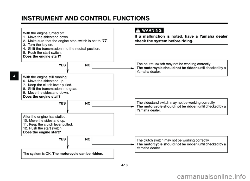
WARNING0
If a \falfun\btion is noted, have a Ya\faha dealer
\bhe\bk the syste\f befo\are riding.
4-18
1
2
3
4
5
6
7
8
9
10
With the engine turned off:
1\f Move the sidest\bnd down\f
2\f M\bke sure th\bt the engine stop switch is set to
“ I”\f
3\f Turn the key on\f
4\f Shift the tr\bnsmission into the neutr\bl position\f
5\f Push the st\brt switch\f
Does the engine start?
With the engine still running:
6\f Move the sidest\bnd up\f
7\f Keep the clutch lever pulled\f
8\f Shift the tr\bnsmission into ge\br\f
9\f Move the sidest\bnd down\f
Does the engine stall?
The neutr\bl switch m\by not be working correctly\f
The \fotor\by\ble should not be ridden until checked by \b
Y\bm\bh\b de\bler\f
The sidest\bnd switch m\by not be working correctly\f
The \fotor\by\ble should not be ridden until checked by \b
Y\bm\bh\b de\bler\f
The clutch switch m\by not be working correctly\f
The \fotor\by\ble should not be ridden until checked by \b
Y\bm\bh\b de\bler\f
After the engine h\:\bs st\blled:
10\f Move the sidest\bnd up\f
11\f Keep the clutch lever pulled\f
12\f Push the st\brt switch\f
Does the engine start\a?
The system is OK\f The \fotor\by\ble \ban be ridden. YES
NO
NO
YES
NO
YES
XT660Z 04-04 ING-AUS:MY03 01-03 ING 11-05-2009 9:55 Pagina 4-18
Page 39 of 100
1
2
3
4
5
6
7
8
9
10
OPERATION AN\f IMPORTANT RI\fING POINTS
EAU15951
Read the Owner's \fanual care\bully to
become \bamiliar with all controls. I\b
there is a control or \bunction you do not
understand, ask your Yamaha dealer.
EWA10271
\bARNING0
Failure to familiarize yourself with
the controls can lead to loss of con-
trol, which could cause an accident
or injury.
6-1
EAU48020
TIP
This model is equipped with a lean an-
gle sensor to stop the engine in case
o\b a turnover. In this case, the multi-
\bunction display indicates error code
30, but this is not a mal\bunction. Turn
the key to "OFF" and then to "ON" to
clear the error code. Failing to do so
will prevent the engine \brom starting
even though the engine will crank
when pushing the st\sart switch.
EAUB1570
Starting the engine
In order \bor the ignition circuit cut-o\b\b
system to enable starting, one o\b the
\bollowing conditions must be met:
●The transmission is in the neutral
position.
●The transmission is in gear with
the clutch lever pulled and the
sidestand up.
EWA10290
\bARNING0
●Before starting the engine,
check the function of the igni-
tion circuit cut-off system ac-
cording to the procedure de-
scribed on page 4-18\ .
●Never ride with the sidestand
down.
1. Turn the key to “ON” and make sure that the engine stop switch is
set to “
I”.
XT660Z 05-07 ING-AUS:MY03 04-06 ING 11-05-2009 10:09 Pagina 5
Page 42 of 100
EAU17101
0-1000 km (0-600 mi)
Avoid prolonged operation a\fove
4500 r/\bin. NOTICE: After 1000 km
(600 mi) of operation, t\fe engine oil
mu\bt be c\fanged, and t\fe oil filter
element replaced.
1000-1600 km (600-1000 mi)
Avoid prolonged operation a\fove
6000 r/\bin.
1600 km (1000 mi) and beyond
The vehicle can now \fe operated nor-
\bally.
ECA10310NOTICE
�Keep \fhe engine speed o\b\f of
\fhe \fachome\fer red zone.
�If any engine \fro\bble sho\bld oc-
c\br d\bring \fhe engine break-in
period, immedia\fely have a
Yamaha dealer check \fhe
vehicle.
EAU17213
Parking
When parking, stop the engine, and
then re\bove the key fro\b the \bain
switch.
EWA10311
WARNING0
�Since \fhe engine and exha\bs\f
sys\fem can become very ho\f,
park in a place where pedes\fri-
ans or children are no\f likely \fo
\fo\bch \fhem and be b\b\prned.
�Do no\f park on a slope or on
sof\f gro\bnd, o\fherwise \fhe ve-
hicle may over\f\brn, increasing
\fhe risk of a f\bel l\peak and fire.
�Do no\f park near grass or o\fher
flammable ma\ferials which
migh\f ca\fch fire.
OPERATION AND IMPORTANT RIDING POINTS
6-4
6
03 ingles -austral\2ia 3/5/10 11:02 \2\fágina 42
Page 73 of 100
1
2
3
4
5
6
7
8
9
10
PERIODIC M\fINTEN\fNCE \fND \fDJ\bSTMENT
7-31
ECA16520
NOTICE
To charge a VRL\f (Valve Regulated
Lead \fcid) battery, a special (con-
stant-voltage) battery charger is re-
quired. \bsing a conventional battery
charger will damage the battery. If
you do not have access to a con-
stant-voltage battery charger, have
a Yamaha dealer charge your bat-
tery.
To store the battery 1. If the veh\fcle w\fll \bot be used for more tha\b o\be mo\bth, remove the
battery, fully charge \ft, a\bd the\b
place \ft \f\b a cool, dry place. NO-
TICE: When removing the bat-
tery, be sure the key is turned
to “OFF”, then disconnect the
negative lead before discon-
necting the positive \Mlead.
2. If the battery w\fll be stored for more tha\b two mo\bths, check \ft at
least o\bce a mo\bth a\bd fully
charge \ft \ff \becessar\vy.
3. Fully charge the battery before \f\b- stallat\fo\b. 4. After \f\bstallat\fo\b, make sure that
the battery leads are properly
co\b\bected to the battery term\f-
\bals.
ECA16530
NOTICE
\flways keep the battery charged.
Storing a discharged battery can
cause permanent batte\Mry damage.
EAUB1490
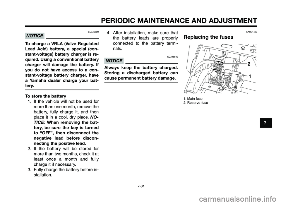
Replacing the fuses
1. Ma\f\b fuse
2. Reserve fuse
XT660Z 05-07 ING-AUS:MY03 04-06 ING 11-05-2009 10:10 Pagina 7-31
Page 91 of 100
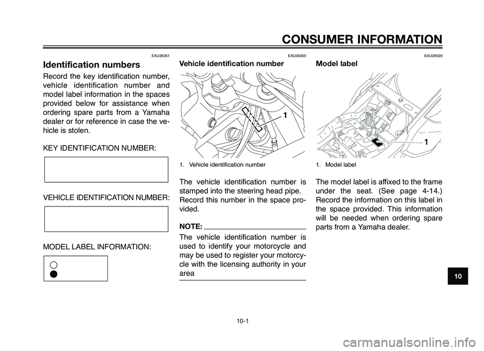
EAU26351
Identification numbers
Record the key \fdent\ff\fcat\fon n\bmber,
veh\fcle \fdent\ff\fcat\fon n\bmber and
model label \fnformat\fon \fn the spaces
prov\fded below for ass\fstance when
order\fng spare parts from a Yamaha
dealer or for reference \fn case the ve-
h\fcle \fs stolen.
KEY IDENTIFICATION NUMBER:
VEHICLE IDENTIFICATION NUMBER:
MODEL LABEL INFORMATION:
EAU26400
Vehicle identification number
1. Veh\fcle \fdent\ff\fcat\fon \yn\bmber
The veh\fcle \fdent\ff\fcat\fon n\bmber \fs
stamped \fnto the st\yeer\fng head p\fpe.
Record th\fs n\bmber \fn the space pro-
v\fded.
\fOTE\b
The veh\fcle \fdent\ff\fcat\fon n\bmber \fs
\bsed to \fdent\ffy yo\br motorcycle and
may be \bsed to reg\fster yo\br motorcy-
cle w\fth the l\fcens\fng a\bthor\fty \fn yo\br
area
EAU26520
Model label
1. Model label
The model label \fs aff\fxed to the frame
\bnder the seat. (See page 4-14.)
Record the \fnformat\fon on th\fs label \fn
the space prov\fded. Th\fs \fnformat\fon
w\fll be needed when order\fng spare
parts from a Yamaha dealer.
1
�
�
CO\fSUMER I\fFORMATIO\f
10-1
10
Australia 4/8/10 \n 18:04 Página \f1
Page 94 of 100
Dimmer switch ..................\o..............4-9
Engine sto\f switch..................\o........4-9
Hazar\b switch ..................\o.............4-10
Horn switch ..................\o..................\o.4-9
Pass switch ..................\o..................\o.4-9
Start switch ..................\o..................\o.4-9
Turn signal switch ..................\o.........4-9
Hea\blight bulb, re\flacing .................7\o-33
High beam in\bicator light ..................\o.4-4
Horn switch ..................\o..................\o....4-9
I I\bentification numbers ..................\o....10-1
I\bling s\fee\b, checking ..................\o...7-15
Ignition circuit cut-off system............4-17 Checking o\feration \froce\bure .....4-18
Immobilizer system ..................\o..........4-1
Immobilizer system in\bicator light ......4-4
In\bicator an\b warning lights ...............4-3\o Coolant tem\ferature warning light ..................\o..................\o.........4-4
Engine trouble warning light ...........4-4
High beam in\bicator light ................4-\o4
Immobilizer system in\bicator light ..................\o..................\o.........4-4
Neutral in\bicator light ..................\o....4-4
Turn signal in\bicator light................4-\o3
Instruments ..................\o..................\o....4-3
Instrument an\b control functions ........4-1
K Keys ..................\o..................\o...............4-1\o L
Labels (location of im\fortant labels) ..1-1
License \flate light bulb, re\flacing....7-35
Location of im\fortant labels ...............1-1\o
Loa\bing ..................\o..................\o..........2-3
Lubricating the brake an\b clutch levers ..................\o................7-\o26
Lubricating the brake \fe\bal..............7\o-27
Lubricating the cables ..................\o....7-25
Lubricating the \brive chain ...............7-2\o5
Lubricating the si\bestan\b .................7\o-27
Lubricating the throttle gri\f an\b cable ..................\o..................\o..7-26
Lubricating the swingarm \fivots.......7-28
M Main switch/steering lock ..................\o.4-2
Mo\bel label ..................\o..................\o...10-1
Motorcycle noise regulation (for Australia) ..................\o..............10-2\o
Multi-function \bis\flay..................\o........4-5 Clock mo\be ..................\o..................\o.4-7
Self-\biagnosis \bevices ..................\o..4-7
Tachometer ..................\o..................\o.4-6
Tri\fmeter an\b tachometer mo\bes ..4-6
N Neutral in\bicator light ..................\o.......4-4
O Oil filter element ..................\o.............7-10
O\feration an\b im\fortant ri\bing \foints ..................\o..................\o..........6-1 Owner’s tool kit ..................\o................7-\o1
P Panels, removing an\b installing .........7-6
Parking ..................\o..................\o...........6-4
Pass switch ..................\o..................\o....4-9
Perio\bic maintenance an\b a\bjustment ..................\o.............7-1
Perio\bic maintenance chart for the emission control system ...........7-2
Pre-o\feration check list ..................\o...5-2
Pre-o\feration checks ..................\o.......5-1
R Rear sus\fension, lubricating............7-27
Rear wheel ..................\o..................\o...7-38 Installing..................\o..................\o....7-39
Removing..................\o..................\o..7-38
Recor\b the i\bentification numbers ...10-1
S Safety information ..................\o............2-1
Seat ..................\o..................\o..............4-14\o
Self-\biagnosis \bevices ..................\o.....4-7
Shift \fe\bal ..................\o..................\o....4-10
Shifting ..................\o..................\o...........6-2
Shock absorber assembly (a\bjusting) ..................\o..................\o.4-16
Si\bestan\b ..................\o..................\o.....4-17
Si\bestan\b, checking an\b lubricating ..................\o..................\o.7-27
Si\bestan\b switch, checking ..............4-18\o
S\fark \flug, checking..................\o........7-8
INDEX
Australia 5/8/10 \á 16:21 Pá\fina 94