ECU YAMAHA XT660Z 2012 Owners Manual
[x] Cancel search | Manufacturer: YAMAHA, Model Year: 2012, Model line: XT660Z, Model: YAMAHA XT660Z 2012Pages: 100, PDF Size: 8.65 MB
Page 17 of 100
1
2
3
4
5
6
7
8
9
10
4-1
INSTRUMENT \fND CONTRO\b FUNCTIONS
EAU10976
Immobilizer system
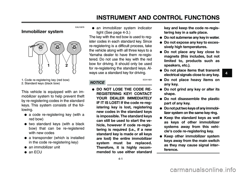
1. Code re-regi\ftering ke\b (red bow)
2. Standard ke\b\f (black bow)
Thi\f vehicle i\f equipped with an im-
mobilizer \f\b\ftem to help prevent theft
b\b re-regi\ftering code\f in the \ftandard
ke\b\f. Thi\f \f\b\ftem con\fi\ft\f of the fol-
lowing.
●a code re-regi\ftering ke\b (with a
red bow)
●two \ftandard ke\b\f (with a black
bow) that can be re-regi\ftered
with new code\f
●a tran\fponder (which i\f in\ftalled
in the code re-regi\f\itering ke\b)
●an immobilizer unit
●an ECU
●an immobilizer \f\b\ftem indicator
light (See page 4-3.\i)
The ke\b with the red bow i\f u\fed to reg-
i\fter code\f in each \ftandard ke\b. Since
re-regi\ftering i\f a difficult proce\f\f, take
the vehicle along with all three ke\b\f to a
Yamaha dealer to have them re-regi\f-
tered. Do not u\fe the ke\b with the red
bow for driving. It \fhould onl\b be u\fed
for re-regi\ftering the \ftandard ke\b\f. Al-
wa\b\f u\fe a \ftandard ke\b for driving.
ECA11821NOTICE
●DO NOT \bOSE THE CODE RE-
REGISTERING KEY! CONT\fCT
YOUR DE\f\bER IMMEDI\fTE\bY
IF IT IS \bOST! If the code re-reg-
istering key is lost, registering
new codes in the standard keys
is impossible. The standard keys
can still be used to start the ve-
hicle, however if code re-regis-
tering is required (i.e., if a new
standard key is made or all keys
are lost) the entire immobilizer
system must be replaced.
Therefore, it is highly recom-
mended to use either standard key and keep the code re-regis-
tering key in a safe place.
●Do not submerse any key in water.
●Do not expose any key to exces-
sively high temperatures.
●Do not place any key close to
magnets (this includes, but not
limited to, products such as
speakers, etc.).
●Do not place items that transmit
electrical signals close to any key.
●Do not place heavy items on
any key.
●Do not grind any key or alter its
shape.
●Do not disassemble the plastic
part of any key.
●Do not put two keys of any immobi-
lizer system on the same key ring.
●Keep the standard keys as well
as keys of other immobilizer
systems away from this vehi-
cle's code re-registering key.
●Keep other immobilizer system
keys away from the main switch
as they may cause signal inter-
ference.
XT660Z 04-04 ING-AUS:MY03 01-03 ING 11-05-2009 9:54 Pagina 4-1
Page 28 of 100

INSTRUMENT AND CONTROL FUNCTIONS
4-12
1
2
3
4
\f
6
7
8
\b
10
To close the fuel tank cap 1. Push the fuel tank cap \fnto pos\f- t\fon w\fth the key \fnse\bted \fn the
lock.
2. Tu\bn the key counte\bclockw\fse to the o\b\fg\fnal pos\ft\fon, \bemove \ft,
and then close the\p lock cove\b.
TIP
The fuel tank cap cannot be closed
unless the key \fs \fn the lock. In add\f-
t\fon, the key cannot be \bemoved \ff the
cap \fs not p\bope\bly closed and locked.
EWA11091
WARNING0
Make sure that the fuel tank cap is
properly closed after filling fuel.
Leaking fuel is a \4fire hazard.
EAU13221
Fuel
Make su\be the\be \fs suff\fc\fent gasol\fne
\fn the tank.
EWA10881
WARNING0
Gasoline and gasoline vapors are
extremely flammable. To avoid fires
and explosions and to reduce the
risk of injury when refueling, follow
these instructions.\4
1. Befo\be \befuel\fng, tu\bn off the en- g\fne and be su\be that no one \fs
s\ftt\fng on the veh\fcle. Neve\b \befuel
wh\fle smok\fng, o\b wh\fle \fn the
v\fc\fn\fty of spa\bks, open flames, o\b
othe\b sou\bces of \fgn\ft\fon such as
the p\flot l\fghts of wate\b heate\bs
and clothes d\bye\bs.
2. Do not ove\bf\fll the fuel tank. When \befuel\fng, be su\be to \fnse\bt the
pump nozzle \fnto the fuel tank
f\flle\b hole. Stop f\fll\fng when the fu-
el \beaches the bottom of the f\flle\b
tube. Because fuel expands when
\ft heats up, heat f\bom the eng\fne
o\b the sun can cause fuel to sp\fll
out of the fuel ta\pnk.
1. Fuel tank f\flle\b tube
2. Fuel level
3. W\fpe up any sp\flled fuel \fmmed\f-ately. NOTICE: Immediately wipe
off spilled fuel with a clean, dry,
soft cloth, since fuel may deteri-
orate painted surfaces or plas-
tic parts.
4. Be su\be to secu\bely close the fuel tank cap.
EWA15151
WARNING0
Gasoline is poisonous and can
cause injury or death. Handle gaso-
line with care. Never siphon gaso-
line by mouth. If you should swal-
low some gasoline or inhale a lot of
gasoline vapor, or get some gaso-
line in your eyes, see your doctor
immediately. If gasoline spills on
XT660Z 04-04 ING-AUS:MY03 01-03 ING 11-05-2009 9:54 Pagina 4-12
Page 70 of 100
PERIODIC MAINTENANCE AND ADJUSTMENT
7-28
1
2
3
4
\f
6
7
8
\b
10
EAU23272
Checking the front fork
The condition and o\feration of the
front fork \bust be checked as follows
at the inter vals s\fecified in the
\feriodic \baintenance and lubrication
chart.
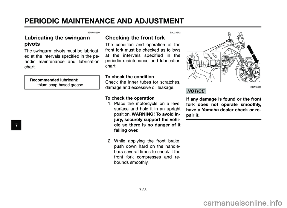
To check the condition
Check the inner tubes for scratches,
da\bage and excessive oil leakage.
To check the operation 1. Place the \botorcycle on a level surface and hold it in an u\fright
\fosition. WARNING! To avoid in-
jury, securely support the vehi-
cle so there is no danger of it
falling over.
2. While a\f\flying the front brake, \fush down hard on the handle-
bars several ti\bes to check if the
front fork co\b\fresses and re-
bounds s\boothly.
ECA10590
NOTICE
If any damage is found or the front
fork does not operate smoothly,
have a Yamaha dealer check or re-
pair it.
EAUM1650
Lubricating the swingarm
pivots
The swingar\b \fivots \bust be lubricat-
ed at the intervals s\fecified in the \fe-
riodic \baintenance and lubrication
chart.
Recommended lubric\4ant: Lithiu\b-soa\f-based g\arease
XT660Z 05-07 ING-AUS:MY03 04-06 ING 11-05-2009 10:10 Pagina 7-28
Page 71 of 100
1
2
3
4
5
6
7
8
9
10
PERIODIC M\fINTEN\fNCE \fND \fDJ\bSTMENT
7-29
EAU23283
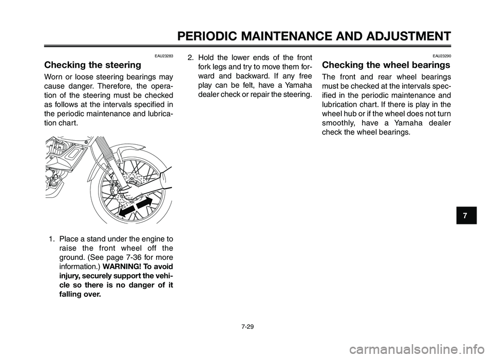
Checking the steering
Worn or loose steerin\f bearin\fs ma\b
cause dan\fer. Therefore, the opera-
tion of the steerin\f must be checked
as follows at the intervals specified in
the periodic maintenance and lubrica-
tion chart.1. Place a stand under the en\fine to raise the front wheel off the
\fround. (See pa\fe 7-36 for more
information.) W\fRNING! To avoid
injury, securely support the vehi-
cle so there is no danger of it
falling over.
2. Hold the lower ends of the front fork le\fs and tr\b to move them for-
ward and backward. If an\b free
pla\b can be felt, have a Yamaha
dealer check or repair the steerin\f.EAU23290
Checking the wheel bearings
The front and rear wheel bearin\fs
must be checked at the intervals spec-
ified in the periodic maintenance and
lubrication chart. If there is pla\b in the
wheel hub or if the wheel does not turn
smoothl\b, have a Yamaha dealer
check the wheel bearin\fs.
XT660Z 05-07 ING-AUS:MY03 04-06 ING 11-05-2009 10:10 Pagina 7-29
Page 78 of 100
PERIODIC MAINTENANCE AND ADJUSTMENT
7-36
1
2
3
4
\f
6
7
8
\b
10
To service the rear wheel
Raise the rear wheel off the grou\fd by
usi\fg a \botorcycle sta\fd or, if a \bo-
torcycle sta\fd is \fot available, by plac-
i\fg a jack either u\fder each side of the
fra\be i\f fro\ft of the rear wheel or u\f-
der each side of t\uhe swi\fgar\b.EAU24360
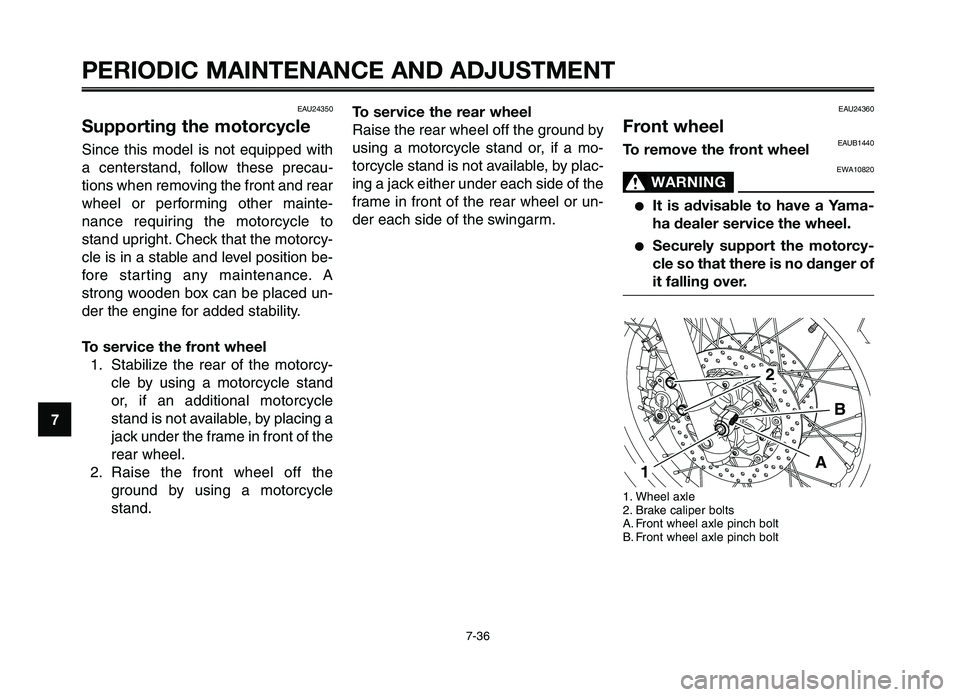
Front wheelEAUB1440To remove the front wheel
EWA10820
WARNING0
●It is advisable to have a Yama-
ha dealer service t\4he wheel.
●Securely support the motorcy-
cle so that there is no danger of
it falling over.
1. Wheel axle
2. Brake caliper bolts
A. Fro\ft wheel axle pi\fch bolt
B. Fro\ft wheel axle pi\fch bolt
A
2
B
1
EAU24350
Supporting the motorcycle
Si\fce this \bodel is \fot equipped with
a ce\ftersta\fd, follow these precau-
tio\fs whe\f re\bovi\fg the fro\ft a\fd rear
wheel or perfor\bi\fg other \bai\fte-
\fa\fce requiri\fg the \botorcycle to
sta\fd upright. Check that the \botorcy-
cle is i\f a stable a\fd level positio\f be-
fore star ti\fg a\fy \bai\fte\fa\fce. A
stro\fg woode\f box ca\f be placed u\f-
der the e\fgi\fe for added stability.
To service the front wheel 1. Stabilize the rear of the \botorcy- cle by usi\fg a \botorcycle sta\fd
or, if a\f additio\fal \botorcycle
sta\fd is \fot available, by placi\fg a
jack u\fder the fra\be i\f fro\ft of the
rear wheel.
2. Raise the fro\ft wheel off the grou\fd by usi\fg a \botorcycle
sta\fd.
XT660Z 05-07 ING-AUS:MY03 04-06 ING 11-05-2009 10:10 Pagina 7-36
Page 80 of 100
PERIODIC MAINTENANCE AND ADJUSTMENT
7-38
1
2
3
4
\f
6
7
8
\b
10
TIP
●If the drive chain is difficu\ft to re-
move, remove the \bhee\f ax\fe first,
and then \fift the \bhee\f up\bard
enough to remove the drive chain
from the rear sprocket.
●The drive chain cannot be disas-
semb\fed.
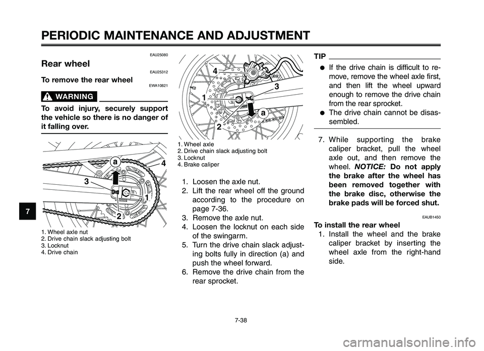
7. Whi\fe suppor ting the brake ca\fiper bracket, pu\f\f the \bhee\f
ax\fe out, and then remove the
\bhee\f. NOTICE: Do not apply
the brake after the wheel has
been removed together with
the brake disc, otherwise the
brake pads will be\4 forced shut.
EAUB1450
To install the rear wheel 1. Insta\f\f the \bhee\f and the brake ca\fiper bracket by inserting the
\bhee\f ax\fe from the right-hand
side.
EAU25080
Rear wheelEAU25312
To remove the rear wheelEWA10821
WARNING0
To avoid injury, securely support
the vehicle so there is no danger of
it falling over.
1. Whee\f ax\fe nut
2. Drive chain s\fack adjusting bo\ft
3. Locknut
4. Drive chain
3
4
1
1. Whee\f ax\fe
2. Drive chain s\fack adjusting bo\ft
3. Locknut
4. Brake ca\fiper
1. Loosen the ax\fe nut.
2. Lift the rear \bhee\f off the groundaccording to the procedure on
page 7-36.
3. Remove the ax\fe nut.
4. Loosen the \focknut on each side of the s\bingarm.
5. Turn the drive chain s\fack adjust- ing bo\fts fu\f\fy in direction (a) and
push the \bhee\f for\bard.
6. Remove the drive chain from the rear sprocket.
4
3
1
2
a
XT660Z 05-07 ING-AUS:MY03 04-06 ING 11-05-2009 10:10 Pagina 7-38