AUX YAMAHA XV535 2000 Owners Manual
[x] Cancel search | Manufacturer: YAMAHA, Model Year: 2000, Model line: XV535, Model: YAMAHA XV535 2000Pages: 87, PDF Size: 17.84 MB
Page 15 of 87

L
3-1
INSTRUMENT AND CONTROL FUNCTIONS
/Net/layout8/layout_G2/work/Imai_work/OM-PS/AA9149_XV535-E6/English/E-3.frame
EAU00027
EAU00028
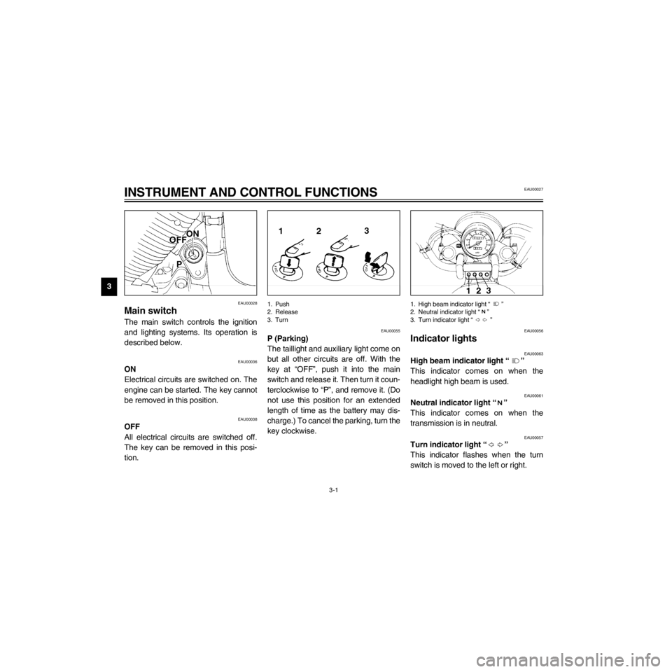
Main switch
The main switch controls the ignition
and lighting systems. Its operation is
described below.
EAU00036
ON
Electrical circuits are switched on. The
engine can be started. The key cannot
be removed in this position.
EAU00038
OFF
All electrical circuits are switched off.
The key can be removed in this posi-
tion.
1. Push
2. Release
3. Turn
EAU00055
P (Parking)
The taillight and auxiliary light come on
but all other circuits are off. With the
key at ÒOFFÓ, push it into the main
switch and release it. Then turn it coun-
terclockwise to ÒPÓ, and remove it. (Do
not use this position for an extended
length of time as the battery may dis-
charge.) To cancel the parking, turn the
key clockwise.
1. High beam indicator light Ò Ó
2. Neutral indicator light Ò Ó
3. Turn indicator light Ò Ó
EAU00056
Indicator lights
EAU00063
High beam indicator light Ò Ó
This indicator comes on when the
headlight high beam is used.
EAU00061
Neutral indicator light Ò Ó
This indicator comes on when the
transmission is in neutral.
EAU00057
Turn indicator light Ò Ó
This indicator flashes when the turn
switch is moved to the left or right.
Page 17 of 87

L
3-3
INSTRUMENT AND CONTROL FUNCTIONS
/Net/layout8/layout_G2/work/Imai_work/OM-PS/AA9149_XV535-E6/English/E-3.frame
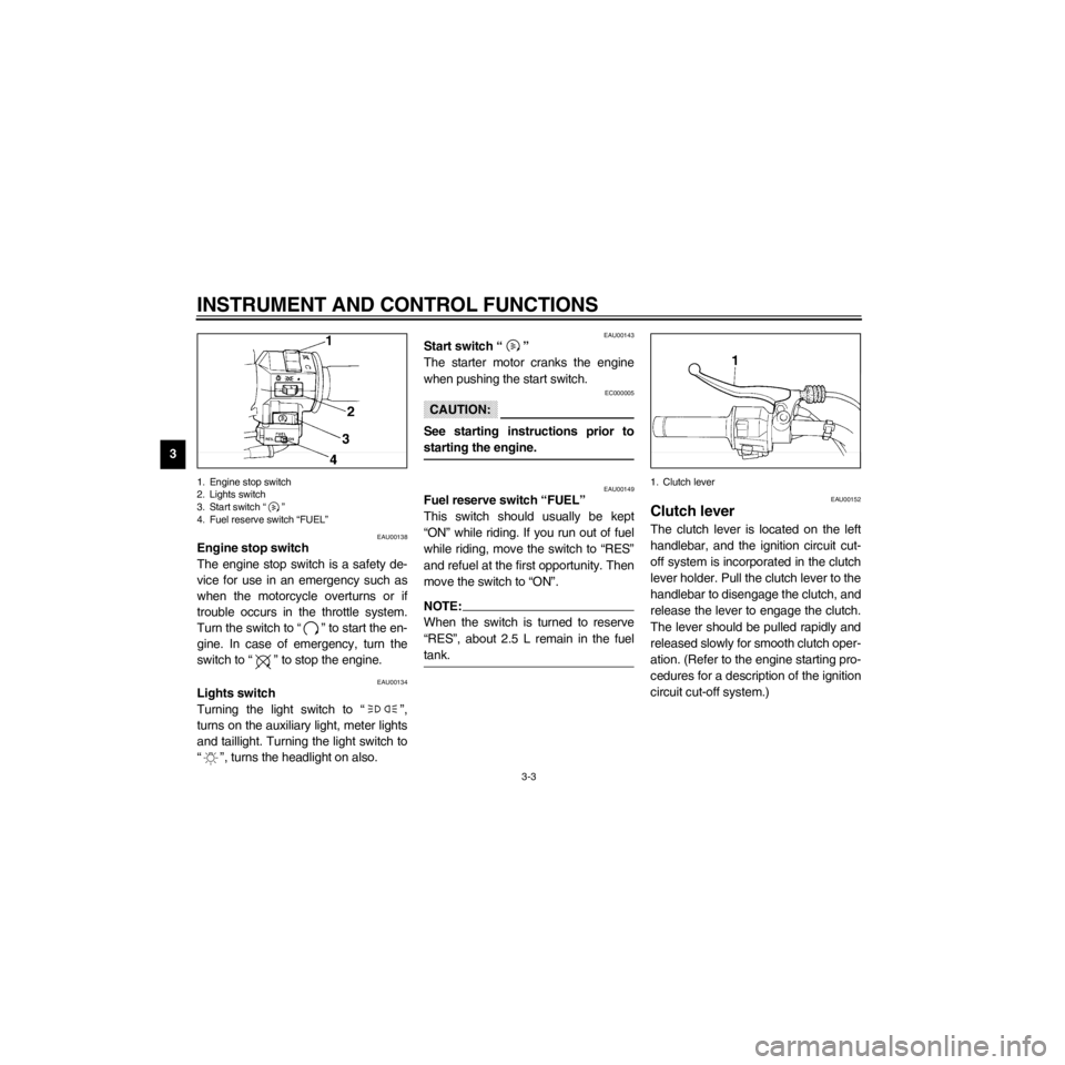
1. Engine stop switch
2. Lights switch
3. Start switch Ò Ó
4. Fuel reserve switch ÒFUELÓ
EAU00138
Engine stop switch
The engine stop switch is a safety de-
vice for use in an emergency such as
when the motorcycle overturns or if
trouble occurs in the throttle system.
Turn the switch to Ò Ó to start the en-
gine. In case of emergency, turn the
switch to Ò Ó to stop the engine.
EAU00134
Lights switch
Turning the light switch to Ò Ó,
turns on the auxiliary light, meter lights
and taillight. Turning the light switch to
Ò Ó, turns the headlight on also.
EAU00143
Start switch Ò Ó
The starter motor cranks the engine
when pushing the start switch.
EC000005
CAUTION:
See starting instructions prior to
starting the engine.
EAU00149
Fuel reserve switch ÒFUELÓ
This switch should usually be kept
ÒONÓ while riding. If you run out of fuel
while riding, move the switch to ÒRESÓ
and refuel at the first opportunity. Then
move the switch to ÒONÓ.
When the switch is turned to reserve
ÒRESÓ, about 2.5 L remain in the fuel
tank.
1. Clutch lever
EAU00152
Clutch lever
The clutch lever is located on the left
handlebar, and the ignition circuit cut-
off system is incorporated in the clutch
lever holder. Pull the clutch lever to the
handlebar to disengage the clutch, and
release the lever to engage the clutch.
The lever should be pulled rapidly and
released slowly for smooth clutch oper-
ation. (Refer to the engine starting pro-
cedures for a description of the ignition
circuit cut-off system.)
Page 80 of 87

R
8-4
SPECIFICATIONS
/Net/layout8/layout_G2/work/Imai_work/OM-PS/AA9149_XV535-E6/English/E-8.frame
Bulb voltage, wattage ´
quantity
Headlight 12 V, 60/55 W ´ 1
Auxiliary light 12 V, 4 W ´ 1 (except for GB)
12 V, 3.4 W ´ 1(for GB)
Tail/brake light 12 V, 5/21 W ´ 2
Front ßasher light 12 V, 21 W ´ 2
Rear ßasher light 12 V, 21 W ´ 2
Meter light 14 V, 3 W ´ 1
Neutral indicator light 14 V, 3 W ´ 1
High beam indicator light 12 V, 1.7 W ´ 1
Turn indicator light 14 V, 3 W ´ 1
Fuses
Main fuse 30 A
Ignition fuse 15 A
Signaling system fuse 15 A
Headlight fuse 15 A