lock YAMAHA XV535 2001 Owners Manual
[x] Cancel search | Manufacturer: YAMAHA, Model Year: 2001, Model line: XV535, Model: YAMAHA XV535 2001Pages: 96, PDF Size: 10.38 MB
Page 15 of 96
INSTRUMENT AND CONTROL FUNCTIONS
3
Main switch ........................................................................................ 3-1
Indicator lights .................................................................................... 3-1
Speedometer unit .............................................................................. 3-2
Handlebar switches ............................................................................ 3-2
Clutch lever ........................................................................................ 3-3
Shift pedal .......................................................................................... 3-4
Brake lever ......................................................................................... 3-4
Brake pedal ........................................................................................ 3-4
Fuel tank cap ..................................................................................... 3-5
Fuel .................................................................................................... 3-5
Starter (choke) lever ........................................................................... 3-6
Steering lock ..................................................................................... 3-7
Seats ................................................................................................. 3-7
Helmet holder ..................................................................................... 3-9
Adjusting the shock absorber assemblies ......................................... 3-9
Sidestand ......................................................................................... 3-10
Ignition circuit cut-off system ............................................................ 3-10
E_3bt.book Page 1 Thursday, September 7, 2000 10:01 AM
Page 20 of 96
INSTRUMENT AND CONTROL FUNCTIONS
3-5
3
EAU03712
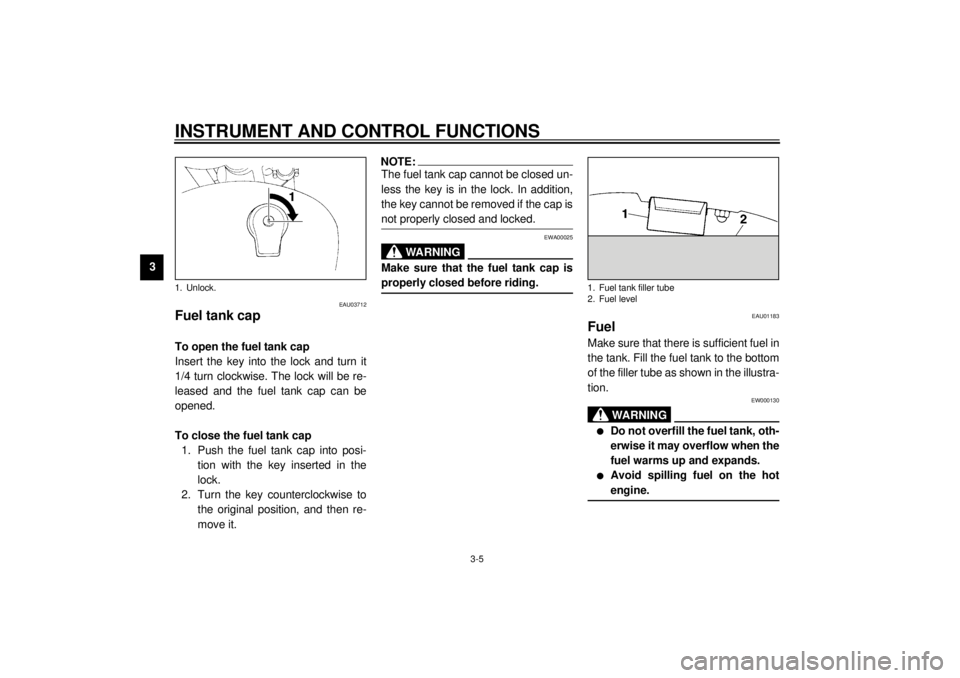
Fuel tank cap To open the fuel tank cap
Insert the key into the lock and turn it
1/4 turn clockwise. The lock will be re-
leased and the fuel tank cap can be
opened.
To close the fuel tank cap
1. Push the fuel tank cap into posi-
tion with the key inserted in the
lock.
2. Turn the key counterclockwise to
the original position, and then re-
move it.
NOTE:_ The fuel tank cap cannot be closed un-
less the key is in the lock. In addition,
the key cannot be removed if the cap is
not properly closed and locked. _
EWA00025
WARNING
_ Make sure that the fuel tank cap is
properly closed before riding. _
EAU01183
FuelMake sure that there is sufficient fuel in
the tank. Fill the fuel tank to the bottom
of the filler tube as shown in the illustra-
tion.
EW000130
WARNING
@ l
Do not overfill the fuel tank, oth-
erwise it may overflow when the
fuel warms up and expands.
l
Avoid spilling fuel on the hot
engine.
@
1. Unlock.
1. Fuel tank filler tube
2. Fuel level
E_3bt.book Page 5 Thursday, September 7, 2000 10:01 AM
Page 22 of 96
INSTRUMENT AND CONTROL FUNCTIONS
3-7
3
EAU02934
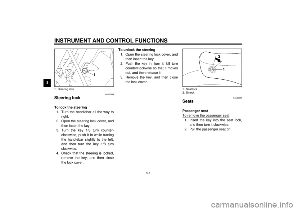
Steering lock To lock the steering
1. Turn the handlebar all the way to
right.
2. Open the steering lock cover, and
then insert the key.
3. Turn the key 1/8 turn counter-
clockwise, push it in while turning
the handlebar slightly to the left,
and then turn the key 1/8 turn
clockwise.
4. Check that the steering is locked,
remove the key, and then close
the lock cover.To unlock the steering
1. Open the steering lock cover, and
then insert the key.
2. Push the key in, turn it 1/8 turn
counterclockwise so that it moves
out, and then release it.
3. Remove the key, and then close
the lock cover.
EAU02940
Seats Passenger seat
To remove the passenger seat1. Insert the key into the seat lock,
and then turn it clockwise.
2. Pull the passenger seat off.
1. Steering lock
1. Seat lock
2. Unlock.
E_3bt.book Page 7 Thursday, September 7, 2000 10:01 AM
Page 23 of 96
INSTRUMENT AND CONTROL FUNCTIONS
3-8
3
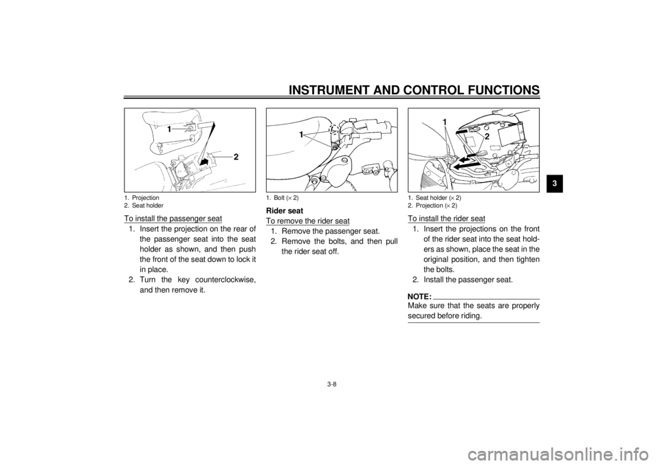
To install the passenger seat
1. Insert the projection on the rear of
the passenger seat into the seat
holder as shown, and then push
the front of the seat down to lock it
in place.
2. Turn the key counterclockwise,
and then remove it.Rider seat
To remove the rider seat
1. Remove the passenger seat.
2. Remove the bolts, and then pull
the rider seat off.To install the rider seat
1. Insert the projections on the front
of the rider seat into the seat hold-
ers as shown, place the seat in the
original position, and then tighten
the bolts.
2. Install the passenger seat.NOTE:@ Make sure that the seats are properly
secured before riding. @
1. Projection
2. Seat holder
1. Bolt (´ 2)
1. Seat holder (´ 2)
2. Projection (´ 2)
E_3bt.book Page 8 Thursday, September 7, 2000 10:01 AM
Page 24 of 96
INSTRUMENT AND CONTROL FUNCTIONS
3-9
3
EAU00260
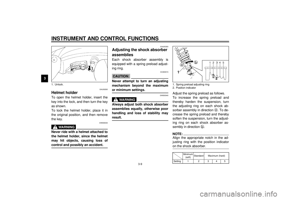
Helmet holderTo open the helmet holder, insert the
key into the lock, and then turn the key
as shown.
To lock the helmet holder, place it in
the original position, and then remove
the key.
EW000030
WARNING
@ Never ride with a helmet attached to
the helmet holder, since the helmet
may hit objects, causing loss of
control and possibly an accident. @
EAU00300
Adjusting the shock absorber
assemblies Each shock absorber assembly is
equipped with a spring preload adjust-
ing ring.
EC000015
CAUTION:@ Never attempt to turn an adjusting
mechanism beyond the maximum
or minimum settings. @
EW000040
WARNING
@ Always adjust both shock absorber
assemblies equally, otherwise poor
handling and loss of stability may
result. @
Adjust the spring preload as follows.
To increase the spring preload and
thereby harden the suspension, turn
the adjusting ring on each shock ab-
sorber assembly in direction
a. To de-
crease the spring preload and thereby
soften the suspension, turn the adjust-
ing ring on each shock absorber as-
sembly in direction
b.NOTE:@ Align the appropriate notch in the ad-
justing ring with the position indicator
on the shock absorber. @CI-01E
1. Unlock.
1. Spring preload adjusting ring
2. Position indicator
Minimum
(soft)Standard Maximum (hard)
Setting1 2 345
E_3bt.book Page 9 Thursday, September 7, 2000 10:01 AM
Page 55 of 96
PERIODIC MAINTENANCE AND MINOR REPAIR
6-18
6
EAU00694
Adjusting the clutch lever free
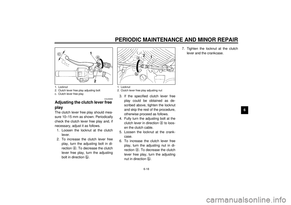
play The clutch lever free play should mea-
sure 10–15 mm as shown. Periodically
check the clutch lever free play and, if
necessary, adjust it as follows.
1. Loosen the locknut at the clutch
lever.
2. To increase the clutch lever free
play, turn the adjusting bolt in di-
rection
a. To decrease the clutch
lever free play, turn the adjusting
bolt in direction
b.3. If the specified clutch lever free
play could be obtained as de-
scribed above, tighten the locknut
and skip the rest of the procedure,
otherwise proceed as follows.
4. Fully turn the adjusting bolt at the
clutch lever in direction
a to loos-
en the clutch cable.
5. Loosen the locknut at the crank-
case.
6. To increase the clutch lever free
play, turn the adjusting nut in di-
rection
a. To decrease the clutch
lever free play, turn the adjusting
nut in direction
b.7. Tighten the locknut at the clutch
lever and the crankcase.1. Locknut
2. Clutch lever free play adjusting bolt
c. Clutch lever free play
1. Locknut
2. Clutch lever free play adjusting nut
E_3bt.book Page 18 Thursday, September 7, 2000 10:01 AM
Page 56 of 96
PERIODIC MAINTENANCE AND MINOR REPAIR
6-19
6
EAU00696
Adjusting the brake lever free
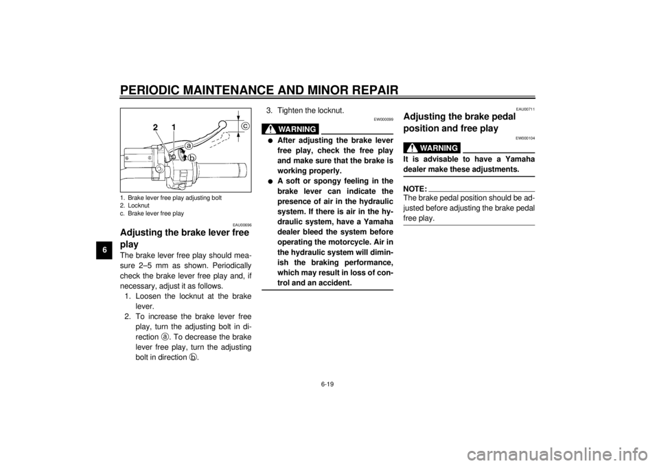
playThe brake lever free play should mea-
sure 2–5 mm as shown. Periodically
check the brake lever free play and, if
necessary, adjust it as follows.
1. Loosen the locknut at the brake
lever.
2. To increase the brake lever free
play, turn the adjusting bolt in di-
rection
a. To decrease the brake
lever free play, turn the adjusting
bolt in direction
b.3. Tighten the locknut.
EW000099
WARNING
@ l
After adjusting the brake lever
free play, check the free play
and make sure that the brake is
working properly.
l
A soft or spongy feeling in the
brake lever can indicate the
presence of air in the hydraulic
system. If there is air in the hy-
draulic system, have a Yamaha
dealer bleed the system before
operating the motorcycle. Air in
the hydraulic system will dimin-
ish the braking performance,
which may result in loss of con-
trol and an accident.
@
EAU00711
Adjusting the brake pedal
position and free play
EW000104
WARNING
@ It is advisable to have a Yamaha
dealer make these adjustments. @NOTE:@ The brake pedal position should be ad-
justed before adjusting the brake pedal
free play. @
1. Brake lever free play adjusting bolt
2. Locknut
c. Brake lever free playE_3bt.book Page 19 Thursday, September 7, 2000 10:01 AM
Page 57 of 96
PERIODIC MAINTENANCE AND MINOR REPAIR
6-20
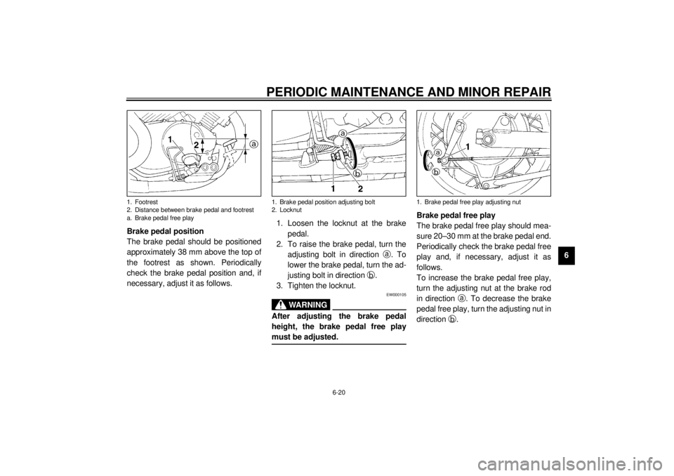
6 Brake pedal position
The brake pedal should be positioned
approximately 38 mm above the top of
the footrest as shown. Periodically
check the brake pedal position and, if
necessary, adjust it as follows.1. Loosen the locknut at the brake
pedal.
2. To raise the brake pedal, turn the
adjusting bolt in direction
a. To
lower the brake pedal, turn the ad-
justing bolt in direction
b.
3. Tighten the locknut.
EW000105
WARNING
@ After adjusting the brake pedal
height, the brake pedal free play
must be adjusted. @
Brake pedal free play
The brake pedal free play should mea-
sure 20–30 mm at the brake pedal end.
Periodically check the brake pedal free
play and, if necessary, adjust it as
follows.
To increase the brake pedal free play,
turn the adjusting nut at the brake rod
in direction
a. To decrease the brake
pedal free play, turn the adjusting nut in
direction
b.
1. Footrest
2. Distance between brake pedal and footrest
a. Brake pedal free play
1. Brake pedal position adjusting bolt
2. Locknut
1. Brake pedal free play adjusting nut
E_3bt.book Page 20 Thursday, September 7, 2000 10:01 AM
Page 59 of 96
PERIODIC MAINTENANCE AND MINOR REPAIR
6-22
6
EAU00727
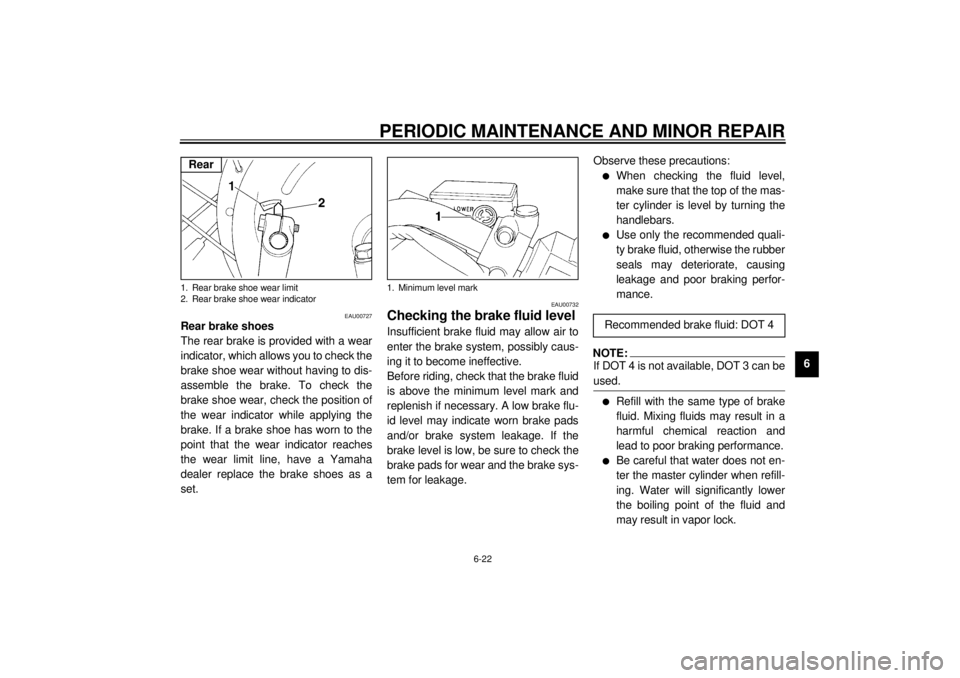
Rear brake shoes
The rear brake is provided with a wear
indicator, which allows you to check the
brake shoe wear without having to dis-
assemble the brake. To check the
brake shoe wear, check the position of
the wear indicator while applying the
brake. If a brake shoe has worn to the
point that the wear indicator reaches
the wear limit line, have a Yamaha
dealer replace the brake shoes as a
set.
EAU00732
Checking the brake fluid level Insufficient brake fluid may allow air to
enter the brake system, possibly caus-
ing it to become ineffective.
Before riding, check that the brake fluid
is above the minimum level mark and
replenish if necessary. A low brake flu-
id level may indicate worn brake pads
and/or brake system leakage. If the
brake level is low, be sure to check the
brake pads for wear and the brake sys-
tem for leakage.Observe these precautions:
l
When checking the fluid level,
make sure that the top of the mas-
ter cylinder is level by turning the
handlebars.
l
Use only the recommended quali-
ty brake fluid, otherwise the rubber
seals may deteriorate, causing
leakage and poor braking perfor-
mance.
NOTE:@ If DOT 4 is not available, DOT 3 can be
used. @l
Refill with the same type of brake
fluid. Mixing fluids may result in a
harmful chemical reaction and
lead to poor braking performance.
l
Be careful that water does not en-
ter the master cylinder when refill-
ing. Water will significantly lower
the boiling point of the fluid and
may result in vapor lock.
1. Rear brake shoe wear limit
2. Rear brake shoe wear indicatorRear
1. Minimum level mark
Recommended brake fluid: DOT 4
E_3bt.book Page 22 Thursday, September 7, 2000 10:01 AM
Page 69 of 96
PERIODIC MAINTENANCE AND MINOR REPAIR
6-32
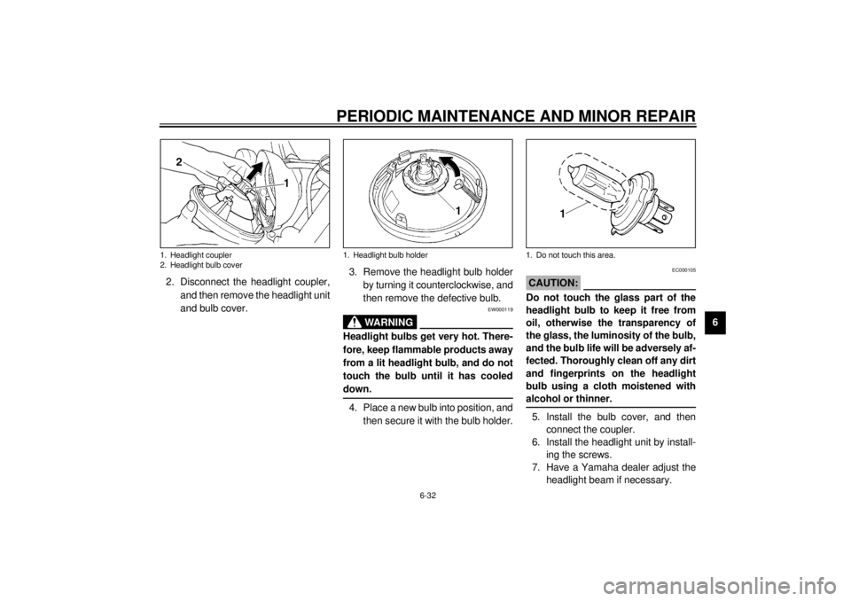
6 2. Disconnect the headlight coupler,
and then remove the headlight unit
and bulb cover.3. Remove the headlight bulb holder
by turning it counterclockwise, and
then remove the defective bulb.
EW000119
WARNING
@ Headlight bulbs get very hot. There-
fore, keep flammable products away
from a lit headlight bulb, and do not
touch the bulb until it has cooled
down. @4. Place a new bulb into position, and
then secure it with the bulb holder.
EC000105
CAUTION:@ Do not touch the glass part of the
headlight bulb to keep it free from
oil, otherwise the transparency of
the glass, the luminosity of the bulb,
and the bulb life will be adversely af-
fected. Thoroughly clean off any dirt
and fingerprints on the headlight
bulb using a cloth moistened with
alcohol or thinner. @5. Install the bulb cover, and then
connect the coupler.
6. Install the headlight unit by install-
ing the screws.
7. Have a Yamaha dealer adjust the
headlight beam if necessary.
1. Headlight coupler
2. Headlight bulb cover
1. Headlight bulb holder
1. Do not touch this area.
E_3bt.book Page 32 Thursday, September 7, 2000 10:01 AM