odometer YAMAHA XVS1100A 2000 Owners Manual
[x] Cancel search | Manufacturer: YAMAHA, Model Year: 2000, Model line: XVS1100A, Model: YAMAHA XVS1100A 2000Pages: 104, PDF Size: 14.79 MB
Page 20 of 104

INSTRUMENT AND CONTROL FUNCTIONS
3-3
3
EAU03192
Engine trouble warning light “ ”
This warning light comes on or flashes
when an electrical circuit monitoring
the engine is defective. When this oc-
curs, have the Yamaha dealer check
the self-diagnosis system.
The electrical circuit of the warning light
can be checked according to the fol-
lowing procedure.
1. Set the engine stop switch to
“
”.
2. Turn the key to “ON”. If the warn-
ing light does not come on, have a
Yamaha dealer check the electri-
cal circuit.
EAU00063
High beam indicator light “ ”
This indicator light comes on when the
high beam of the headlight is switched
on.
EAU03193
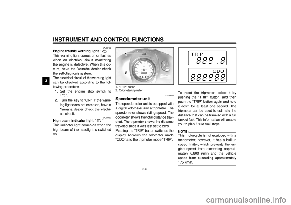
Speedometer unit The speedometer unit is equipped with
a digital odometer and a tripmeter. The
speedometer shows riding speed. The
odometer shows the total distance trav-
eled. The tripmeter shows the distance
traveled since it was last set to zero.
Pushing the “TRIP” button switches the
display between the odometer mode
“ODO” and the tripmeter mode “TRIP”.To reset the tripmeter, select it by
pushing the “TRIP” button, and then
push the “TRIP” button again and hold
it down for at least one second. The
tripmeter can be used to estimate the
distance that can be traveled with a full
tank of fuel. This information will enable
you to plan future fuel stops.
NOTE:@ This motorcycle is not equipped with a
tachometer; however, it has a built-in
speed limiter, which prevents the en-
gine speed from exceeding approxi-
mately 6,800 r/min and the vehicle
speed from exceeding approximately
175 km/h. @
1. “TRIP” button
2. Odometer/tripmeter
E_5KS.book Page 3 Monday, August 21, 2000 10:48 AM
Page 77 of 104

PERIODIC MAINTENANCE AND MINOR REPAIR
6-28
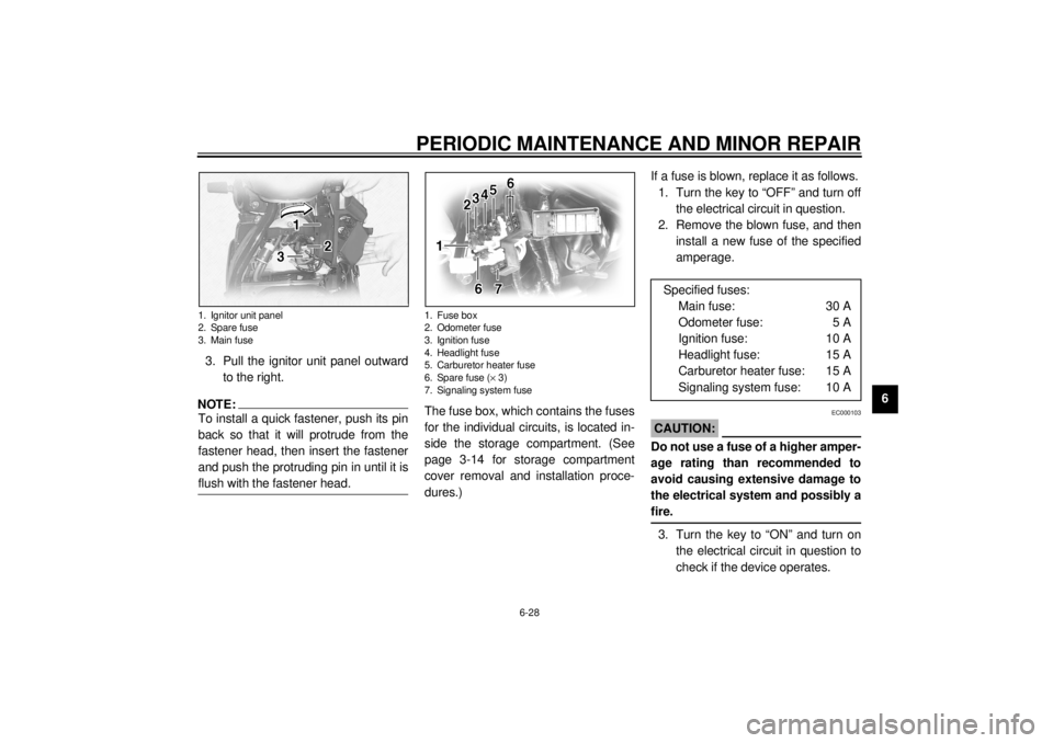
6 3. Pull the ignitor unit panel outward
to the right.
NOTE:@ To install a quick fastener, push its pin
back so that it will protrude from the
fastener head, then insert the fastener
and push the protruding pin in until it is
flush with the fastener head. @
The fuse box, which contains the fuses
for the individual circuits, is located in-
side the storage compartment. (See
page 3-14 for storage compartment
cover removal and installation proce-
dures.)If a fuse is blown, replace it as follows.
1. Turn the key to “OFF” and turn off
the electrical circuit in question.
2. Remove the blown fuse, and then
install a new fuse of the specified
amperage.
EC000103
CAUTION:@ Do not use a fuse of a higher amper-
age rating than recommended to
avoid causing extensive damage to
the electrical system and possibly a
fire. @3. Turn the key to “ON” and turn on
the electrical circuit in question to
check if the device operates.
1. Ignitor unit panel
2. Spare fuse
3. Main fuse
1. Fuse box
2. Odometer fuse
3. Ignition fuse
4. Headlight fuse
5. Carburetor heater fuse
6. Spare fuse (´ 3)
7. Signaling system fuse
Specified fuses:
Main fuse: 30 A
Odometer fuse: 5 A
Ignition fuse: 10 A
Headlight fuse: 15 A
Carburetor heater fuse: 15 A
Signaling system fuse: 10 A
E_5KS.book Page 28 Monday, August 21, 2000 10:48 AM
Page 94 of 104

SPECIFICATIONS
8-5
8
Bulb voltage, wattage ´ quantity
Headlight 12 V, 60/55 W ´ 1
Auxiliary light 12 V, 4 W ´ 1
Tail/brake light 12 V, 5/21 W ´ 1
Turn signal light 12 V, 21 W ´ 4
Meter light 14 V, 1.4 W ´ 2
Oil level warning light 12 V, 1.7 W ´ 1
Neutral indicator light 12 V, 1.7 W ´ 1
Turn signal indicator light 12 V, 1.7 W ´ 1
Engine trouble warning light 12 V, 1.7 W ´ 1
High beam indicator light 12 V, 1.7 W ´ 1
Fuses
Main fuse 30 A
Signaling system fuse 10 A
Odometer fuse 5 A
Ignition fuse 10 A
Headlight fuse 15 A
Carburetor heater fuse 15 A
E_5KS.book Page 5 Monday, August 21, 2000 10:48 AM