Speedometer YAMAHA XVS125 2000 Owners Manual
[x] Cancel search | Manufacturer: YAMAHA, Model Year: 2000, Model line: XVS125, Model: YAMAHA XVS125 2000Pages: 86, PDF Size: 3.07 MB
Page 7 of 86

EAU00009
TABLE OF CONTENTS
GIVE SAFETY THE RIGHT OF WAY ..................1-1
DESCRIPTION ....................................................2-1
Left view .............................................................2-1
Right view ..........................................................2-2
Controls and Instruments ...................................2-3
INSTRUMENT AND CONTROL
FUNCTIONS ........................................................3-1
Main switch/steering lock ...................................3-1
Indicator lights ....................................................3-2
Speedometer unit ..............................................3-2
Anti-theft alarm (optional)...................................3-3
Handlebar switches............................................3-3
Clutch lever ........................................................3-5
Shift pedal ..........................................................3-5
Brake lever .........................................................3-5
Brake pedal ........................................................3-6
Fuel tank cap .....................................................3-6
Fuel ....................................................................3-7
Fuel cock............................................................3-7
Starter (choke) lever ..........................................3-8
Helmet holder.....................................................3-9
Adjusting the shock absorber assemblies..........3-9
Sidestand .........................................................3-10
Ignition circuit cut-off system............................3-10PRE-OPERATION CHECKS ...............................4-1
Pre-operation check list .....................................4-1
OPERATION AND IMPORTANT RIDING
POINTS................................................................5-1
Starting the engine .............................................5-1
Starting a warm engine ......................................5-3
Shifting ...............................................................5-3
Recommended shift points
(for Switzerland only) .......................................5-4
Tips for reducing fuel consumption ....................5-4
Engine break-in ..................................................5-4
Parking ...............................................................5-5
PERIODIC MAINTENANCE AND MINOR
REPAIR................................................................6-1
Owner’s tool kit ..................................................6-1
Periodic maintenance and lubrication chart .......6-2
Removing and installing panels .........................6-5
Checking the spark plugs...................................6-7
Engine oil and oil filter element ..........................6-9
Cleaning the air filter element ..........................6-12
Adjusting the carburetor ...................................6-14
Adjusting the engine idling speed ....................6-14
Adjusting the throttle cable free play ................6-15
Adjusting the valve clearance ..........................6-161
2
3
4
5
6
5JX-9-E0 4/9/0 4:11 AM Page 5
Page 12 of 86

DESCRIPTION
2
2-3
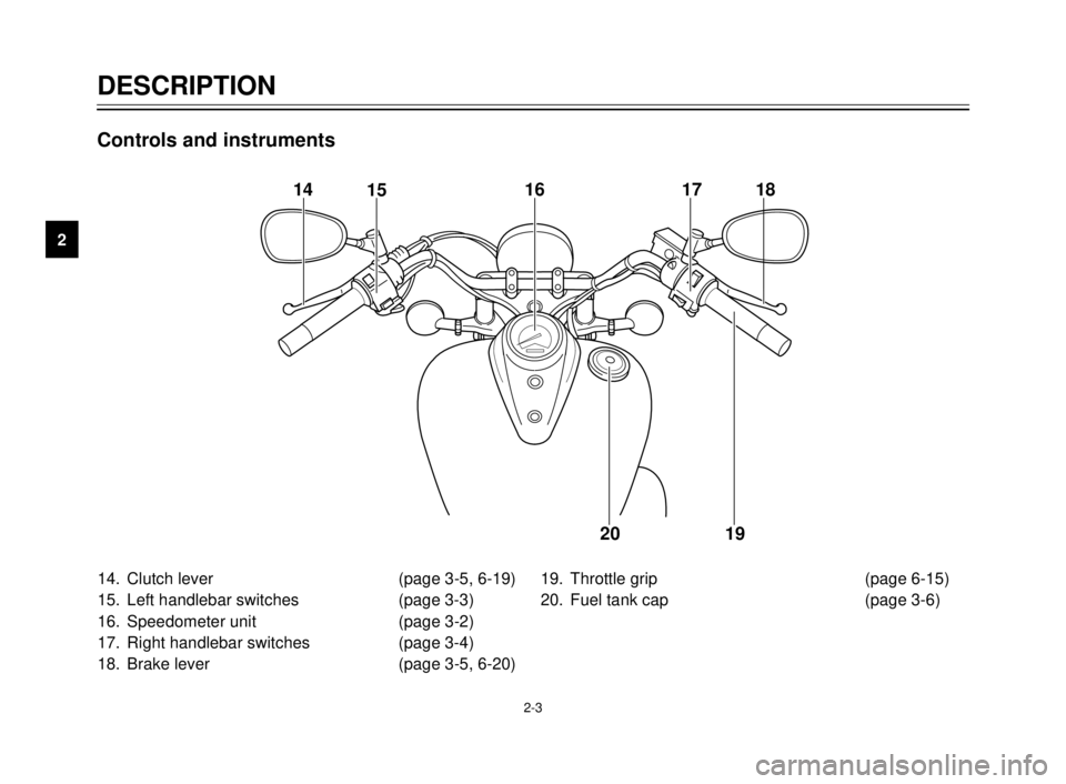
14. Clutch lever (page 3-5, 6-19)
15. Left handlebar switches (page 3-3)
16. Speedometer unit (page 3-2)
17. Right handlebar switches (page 3-4)
18. Brake lever (page 3-5, 6-20)19. Throttle grip (page 6-15)
20. Fuel tank cap (page 3-6)
14
1516 17 18
19 20
Controls and instruments
5JX-9-E0 4/9/0 4:11 AM Page 10
Page 14 of 86

3-2
INSTRUMENT AND CONTROL FUNCTIONS
3
EAU00056
Indicator lights
EAU00063
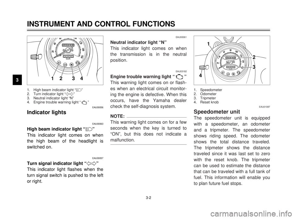
High beam indicator light “&”
This indicator light comes on when
the high beam of the headlight is
switched on.
EAU00057
Turn signal indicator light “5”
This indicator light flashes when the
turn signal switch is pushed to the left
or right.
20
40
60
0km/h
80100120
140
160
12 34
EAU00061
Neutral indicator light “N”
This indicator light comes on when
the transmission is in the neutral
position.
EAU03182
Engine trouble warning light “ ”
This warning light comes on or flash-
es when an electrical circuit monitor-
ing the engine is defective. When this
occurs, have the Yamaha dealer
check the self-diagnosis system.
NOTE:
This warning light comes on for a few
seconds when the key is turned to
“ON”, but this does not indicate a
malfunction.
1. High beam indicator light “&”
2. Turn indicator light “5”
3. Neutral indicator light “N”
4. Engine trouble warning light “ ”
EAU01087
Speedometer unit
The speedometer unit is equipped
with a speedometer, an odometer
and a tripmeter. The speedometer
shows riding speed. The odometer
shows the total distance traveled.
The tripmeter shows the distance
traveled since it was last set to zero
with the reset knob. The tripmeter
can be used to estimate the distance
that can be traveled with a full tank of
fuel. This information will enable you
to plan future fuel stops.
1. Speedometer
2. Odometer
3. Tripmeter
4. Reset knob
20
40
60
0km/h
80100120
140
160
1
2
3
4
5JX-9-E0 4/9/0 4:11 AM Page 12
Page 68 of 86

6-38
6
PERIODIC MAINTENANCE AND MINOR REPAIR
EAU03239
Front wheel
To remove the front wheelEW000122
w
8It is advisable to have a
Yamaha dealer service the
wheel.
8Securely support the motorcy-
cle so that there is no danger
of it falling over.
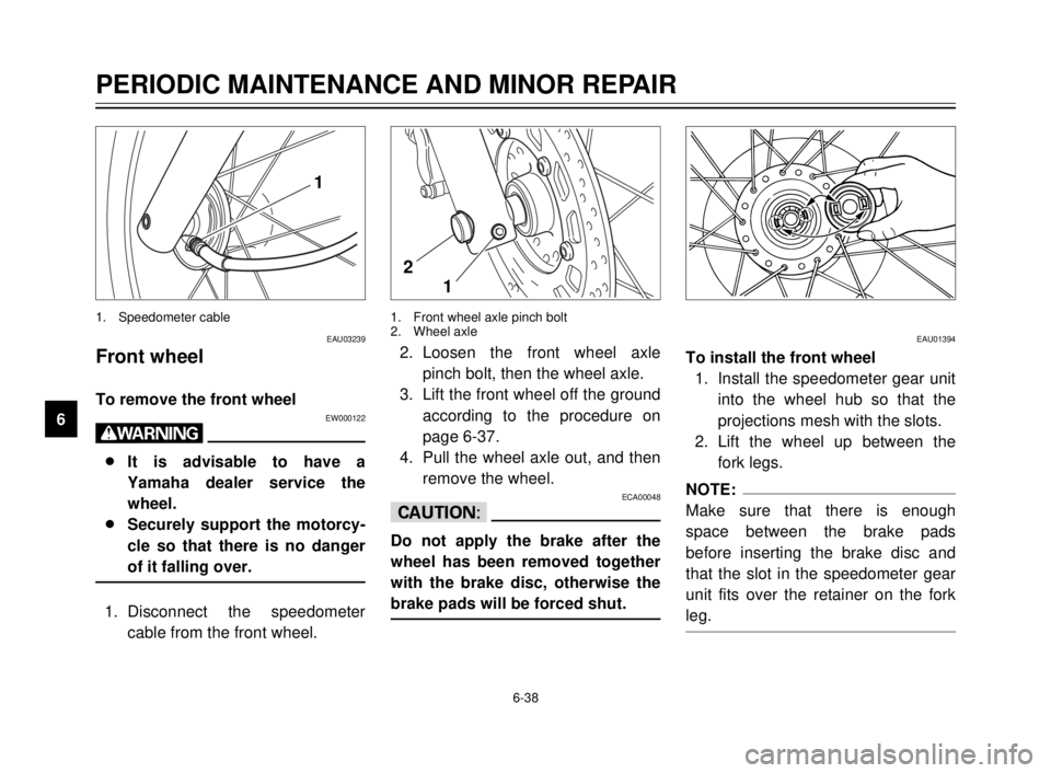
1. Disconnect the speedometer
cable from the front wheel.
1. Speedometer cable
1
2. Loosen the front wheel axle
pinch bolt, then the wheel axle.
3. Lift the front wheel off the ground
according to the procedure on
page 6-37.
4. Pull the wheel axle out, and then
remove the wheel.
ECA00048
cC
Do not apply the brake after the
wheel has been removed together
with the brake disc, otherwise the
brake pads will be forced shut.
1. Front wheel axle pinch bolt
2. Wheel axle
1 2
EAU01394
To install the front wheel
1. Install the speedometer gear unit
into the wheel hub so that the
projections mesh with the slots.
2. Lift the wheel up between the
fork legs.
NOTE:
Make sure that there is enough
space between the brake pads
before inserting the brake disc and
that the slot in the speedometer gear
unit fits over the retainer on the fork
leg.
5JX-9-E0 4/9/0 4:11 AM Page 66
Page 69 of 86

1
2
3
4
5
6
7
8
9
6-39
PERIODIC MAINTENANCE AND MINOR REPAIR
3. Insert the wheel axle.
4. Lower the front wheel so that it is
on the ground.
5. Push down hard on the handle-
bar several times to check for
proper fork operation.
6. Tighten the wheel axle to the
specified torque.
Tightening torque:
Wheel axle:
59 Nm (5.9 m·kg)
7. Install the front wheel axle pinch
bolt, and then tighten it to the
specified torque.
8. Connect the speedometer cable.
EAU03189
Rear wheel
To remove the rear wheelEW000122
w
8It is advisable to have a
Yamaha dealer service the
wheel.
8Securely support the motorcy-
cle so that there is no danger
of it falling over.
1. Loosen the axle nut and the
brake torque rod nut at the brake
shoe plate.
1. Axle nut
1
Tightening torque:
Front wheel axle pinch bolt:
20 Nm (2.0 m·kg)
5JX-9-E0 4/9/0 4:11 AM Page 67