brake light YAMAHA YBR125 2004 Owners Manual
[x] Cancel search | Manufacturer: YAMAHA, Model Year: 2004, Model line: YBR125, Model: YAMAHA YBR125 2004Pages: 83, PDF Size: 3.16 MB
Page 11 of 83

CONTENTS
DESCRIPTION............................................................. 1-1
MACHINE IDENTIFICATION....................................... 2-1
Vehicle identification number ................................. 2-1
Engine serial number............................................ 2-1
CONTROL FUNCTIONS.............................................. 3-1
Main switch ............................................................ 3-1
Indicator lights ........................................................ 3-2
Speedometer..........................................................3-3
Fuel gauge............................................................. 3-3
Handlebar switches over left .................................. 3-4
Handlebar switches over right.............................. 3-5
Clutch lever............................................................ 3-6
Shift pedal............................................................. 3-6
Front brake lever................................................... 3-7
Rear brake pedal................................................... 3-7
Fuel tank cap......................................................... 3-8
Fuel cock............................................................... 3-9
Starter lever......................................................... 3-10
Kick starter .......................................................... 3-10
Steering lock....................................................... 3-11
Seat......................................................................3-12
Side covers......................................................... 3-13
Rear shock absorber adjustment ....................... 3-14
XIPRE-OPERATION CHECKS........................................ 4-1
Engine oil................................................................ 4-3
Tires........................................................................4-3
Fitting/Fasteners....................................................4-6
Switches................................................................ 4-6
Wheels ......................................................... 4-6
Fuel ........................................................... 4-7
OPERATION AND IMPORTANT RIDING POINTS....... 5-1
Starting a cold engine........................................... 5-2
Starting a warm engine .......................................... 5-2
Warming up the engine .......................................... 5-2
Shifting ................................................................... 5-3
Tips for reduccing fuel consumption...................... 5-4
Engine Break-in...................................................... 5-4
Parking ................................................................... 5-5
Page 12 of 83
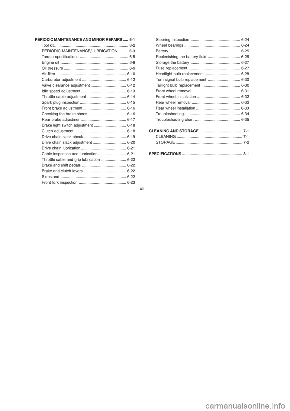
PERIODIC MAINTENANCE AND MINOR REPAIRS..... 6-1
Tool kit..................................................................... 6-2
PERIODIC MAINTENANCE/LUBRICATION......... 6-3
Torque specifications............................................. 6-5
Engine oil................................................................ 6-6
Oil pressure............................................................ 6-9
Air filter.................................................................6-10
Carburetor adjustment.........................................6-12
Valve clearance adjustment.................................6-12
Idle speed adjustment..........................................6-13
Throttle cable adjustment....................................6-14
Spark plug inspection...........................................6-15
Front brake adjustment........................................6-16
Checking the brake shoes ...................................6-16
Rear brake adjustment.........................................6-17
Brake light switch adjustment ..............................6-18
Clutch adjustment................................................ 6-18
Drive chain slack check.......................................6-19
Drive chain slack adjustment...............................6-20
Drive chain lubrication..........................................6-21
Cable inspection and lubrication.......................... 6-21
Throttle cable and grip lubrication .......................6-22
Brake and shift pedals .........................................6-22
Brake and clutch levers .......................................6-22
Sidestand.............................................................6-22
Front fork inspection............................................6-23Steering inspection.............................................. 6-24
Wheel bearings.................................................... 6-24
Battery.................................................................. 6-25
Replenishing the battery fluid .............................. 6-26
Storage the battery.............................................. 6-27
Fuse replacement................................................ 6-27
Headlight bulb replacement................................. 6-28
Turn signal bulb replacement.............................. 6-30
Taillight bulb replacement.................................... 6-30
Front wheel removal............................................. 6-31
Front wheel installation........................................ 6-32
Rear wheel removal............................................. 6-32
Rear wheel installation......................................... 6-33
Troubleshooting.................................................... 6-34
Troubleshooting chart.......................................... 6-35
CLEANING AND STORAGE....................................... 7-1
CLEANING............................................................. 7-1
STORAGE.............................................................. 7-2
SPECIFICATIONS ........................................................ 8-1
XII
CONTENTS
DESCRIPTION............................................................. 1-1
MACHINE IDENTIFICATION....................................... 2-1
Vehicle identikfication number ............................... 2-1
Engine serial number............................................ 2-1
CONTROL FUNCTIONS.............................................. 3-1
Main switch ............................................................ 3-1
Indicator lights ........................................................ 3-2
Speedometer..........................................................3-3
Fuel gauge............................................................. 3-3
Handlebar switches over left .................................. 3-4
Handlebar switches over right.............................. 3-5
Clutch lever............................................................ 3-6
Shift pedal............................................................. 3-6
Front brake lever................................................... 3-7
Rear brake pedal................................................... 3-7
Fuel tank cap......................................................... 3-8
Fuel cock............................................................... 3-9
Starter lever......................................................... 3-10
Kick starter .......................................................... 3-10
Steering lock....................................................... 3-11
Seat......................................................................3-12
Side covers......................................................... 3-13
Rear shock absorber adjustment ....................... 3-14
XIPRE-OPERATION CHECKS........................................ 4-1
Engine oil................................................................ 4-3
Tires........................................................................4-3
Fitting/Fasteners....................................................4-6
Switches................................................................ 4-6
Wheels ......................................................... 4-6
Fuel ........................................................... 4-7
OPERATION AND IMPORTANT RIDING POINTS....... 5-1
Starting a cold engine........................................... 5-2
Starting a warm engine .......................................... 5-2
Warming up the engine .......................................... 5-2
Shifting ................................................................... 5-3
Tips for reduccing fuel consumption...................... 5-4
Engine Break-in...................................................... 5-4
Parking ................................................................... 5-5
Page 30 of 83

4-2 NOTE:
Pre-operation checks should be made each time the motorcycle is used. Such an inspection can be thoroughly accomplished
in a very short time; and the added safety it assures is more than worth the time involved. If any maintenance service or
adjustment is needed, consult the chart above to refer to the pages in which the service or adjustment is described.
1. The engine, exhaust pipe, and muffler will be very hot after the engine has been run.
Be careful not to touch them or to allow any clothing item to contact them during inspection or repair.
2. If any item is not working properly, have it inspected and repaired before operating the motorcycle.
ITEMROUTINE
PAGE
Sidestand
Fittings / FastenersCheck all chassi fittings and fasteners.
Tighten / Adjust, if necessary
Check fuel level / top up as required.
Fuel tank
Lights, signals and switches
BatteryCheck electrolyte level.
Replenish with ìdistilled waterî if necessary.6-22
4-6 , 6-5
4-6 , 6-28 ~ 6-30
6-25 ~ 6-276-22
4-7
Check for proper operation
Front brake and clutch
lever pivotsCheck for smooth operation.
Lubricate if necessary
Check for smooth operation.
Lubricate if necessary
6-22 Check for smooth operation.
Lubricate if necessary Rear brake and shift pedal
shafts
WARNING:
Page 44 of 83
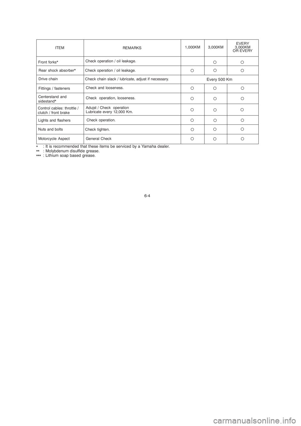
6-4 *
**
***: It is recommended that these items be serviced by a Yamaha dealer.
: Molybdenum disulfide grease.
: Lithium soap based grease.
ITEM
Front forks*
Centerstand and
sidestand*
Control cables: throttle /
clutch / front brakeRear shock absorber*
Drive chain
Fittings / fastenersCheck operation / oil leakage.
Check operation, looseness.
Adujst / Check operation
Lubricate every 12,000 Km. Check chain slack / lubricate, adjust if necessary.
Check and looseness.REMARKS1,000KM
Lights and flashers
Nuts and bolts
Motorcycle AspectCheck operation.
Check tighten.
General Check
EVERY
3,000KM
OR EVERY3,000KM
Check operation / oil leakage.
Every 500 Km
Page 57 of 83
6-17
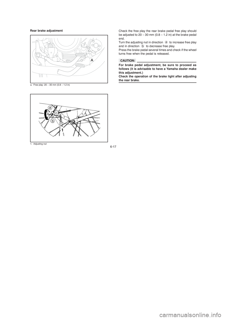
Rear brake adjustment
a. Free play: 20 ~ 30 mm (0.8 ~ 1.2 in)
Check the free play the rear brake pedal free play should
be adjusted to 20 ~ 30 mm (0.8 ~ 1.2 in) at the brake pedal
end.
Turn the adjusting nut in direction a to increase free play
and in direction b to decrease free play.
Press the brake pedal several times and check if the wheel
turns free when the pedal is released.
For brake pedal adjustment, be sure to proceed as
follows (it is advisable to have a Yamaha dealer make
this adjustment.)
Check the operation of the brake light after adjusting
the rear brake.
1. Adjusting nut
CAUTION:
Page 58 of 83
6-18
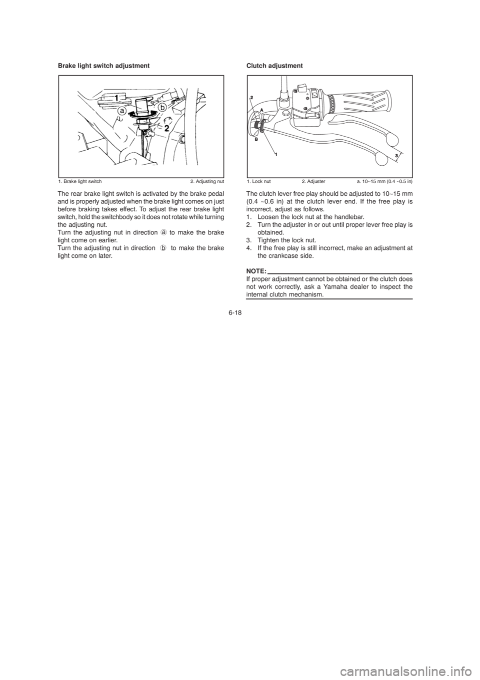
Brake light switch adjustment
The rear brake light switch is activated by the brake pedal
and is properly adjusted when the brake light comes on just
before braking takes effect. To adjust the rear brake light
switch, hold the switchbody so it does not rotate while turning
the adjusting nut.
Turn the adjusting nut in direction a to make the brake
light come on earlier.
Turn the adjusting nut in direction b to make the brake
light come on later.
1. Brake light switch 2. Adjusting nut
Clutch adjustment
The clutch lever free play should be adjusted to 10~15 mm
(0.4 ~0.6 in) at the clutch lever end. If the free play is
incorrect, adjust as follows.
1. Loosen the lock nut at the handlebar.
2. Turn the adjuster in or out until proper lever free play is
obtained.
3. Tighten the lock nut.
4. If the free play is still incorrect, make an adjustment at
the crankcase side.
NOTE:
If proper adjustment cannot be obtained or the clutch does
not work correctly, ask a Yamaha dealer to inspect the
internal clutch mechanism.
1. Lock nut 2. Adjuster a. 10~15 mm (0.4 ~0.5 in)
Page 60 of 83
6-20
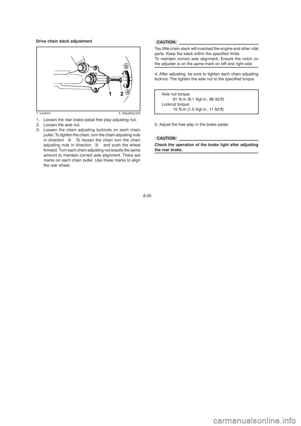
Drive chain slack adjustment
1. Locknut 2. Adjusting bolt
1. Loosen the rear brake pedal free play adjusting nut.
2. Loosen the axle nut.
3. Loosen the chain adjusting locknuts on each chain
puller. To tighten the chain, turn the chain adjusting nuts
in direction a .To loosen the chain turn the chain
adjusting nuts in direction b and push the wheel
forward. Turn each chain adjusting nut exactly the same
amount to maintain correct axle alignment. There are
marks on each chain puller. Use these marks to align
the rear wheel.Too little chain slack will overload the engine and other vital
parts. Keep the slack within the specified limits.
To maintain correct axle alignment, Ensure the notch on
the adjuster is on the same mark on left and right side
4. After adjusting, be sure to tighten each chain adjusting
locknut. The tighten the axle nut to the specified torque
Axle nut torque:
91 N.m (9.1 Kgf.m, 66 lbf.ft)
Locknut torque:
15 N.m (1.5 Kgf.m, 11 lbf.ft)
5. Adjust the free play in the brake pedal.
Check the operation of the brake light after adjusting
the rear brake.
CAUTION:
CAUTION:
Page 73 of 83
6-33
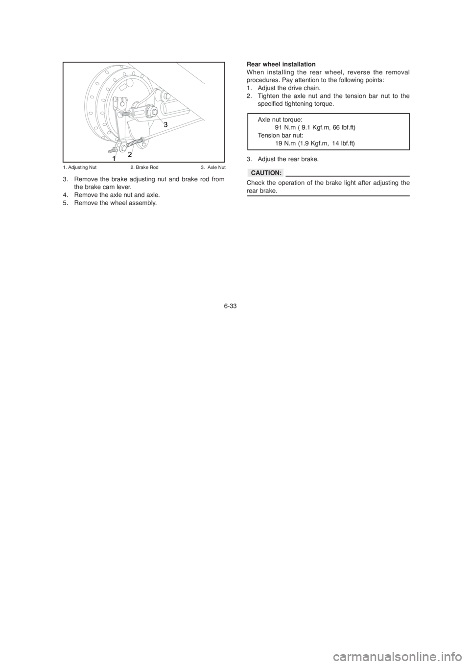
3. Remove the brake adjusting nut and brake rod from
the brake cam lever.
4. Remove the axle nut and axle.
5. Remove the wheel assembly.
1. Adjusting Nut 2. Brake Rod 3. Axle Nut
Rear wheel installation
When installing the rear wheel, reverse the removal
procedures. Pay attention to the following points:
1. Adjust the drive chain.
2. Tighten the axle nut and the tension bar nut to the
specified tightening torque.
Axle nut torque:
91 N.m ( 9.1 Kgf.m, 66 lbf.ft)
Tension bar nut:
19 N.m (1.9 Kgf.m, 14 lbf.ft)
3. Adjust the rear brake.
Check the operation of the brake light after adjusting the
rear brake.
CAUTION:
Page 82 of 83
8-5
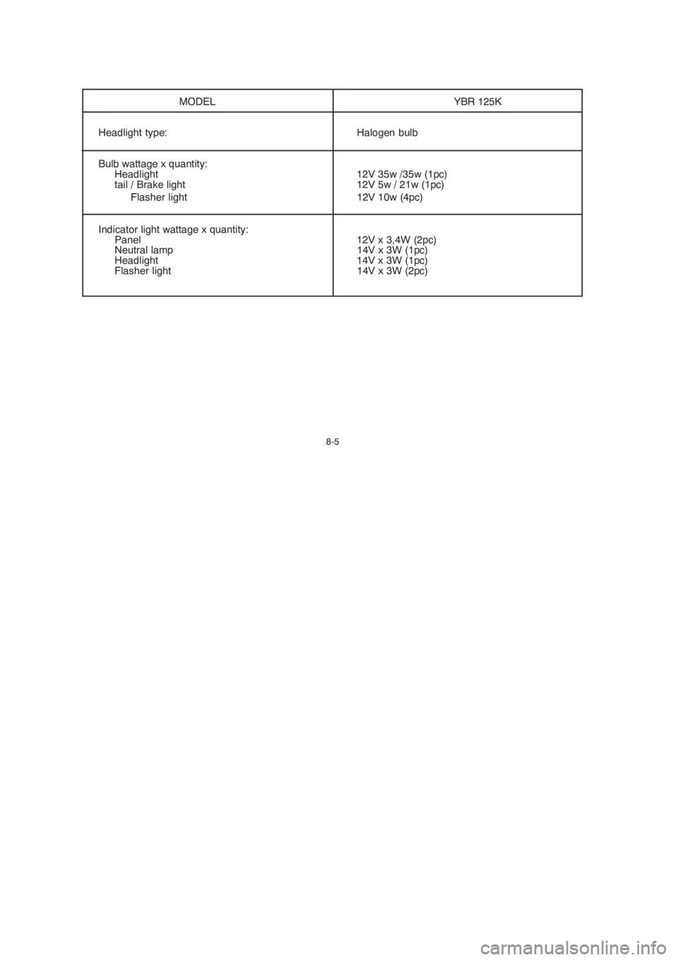
MODEL YBR 125K
Headlight type: Halogen bulb
Bulb wattage x quantity:
Headlight 12V 35w /35w (1pc)
tail / Brake light 12V 5w / 21w (1pc)
Flasher light 12V 10w (4pc)
Indicator light wattage x quantity:
Panel 12V x 3,4W (2pc)
Neutral lamp 14V x 3W (1pc)
Headlight 14V x 3W (1pc)
Flasher light 14V x 3W (2pc)