clutch YAMAHA YBR125 2014 Owners Manual
[x] Cancel search | Manufacturer: YAMAHA, Model Year: 2014, Model line: YBR125, Model: YAMAHA YBR125 2014Pages: 84, PDF Size: 1.82 MB
Page 6 of 84

TABLE OF CONTENTSSAFETY INFORMATION.................. 1-1
DESCRIPTION .................................. 2-1
Left view ......................................... 2-1
Right view ....................................... 2-2
Controls and instruments ............... 2-3
INSTRUMENT AND CONTROL
FUNCTIONS ...................................... 3-1
Main switch/steering lock............... 3-1
Indicator lights and warning light ... 3-2
Speedometer unit ........................... 3-3
Tachometer .................................... 3-3
Self-diagnosis device ..................... 3-3
Fuel gauge ...................................... 3-4
Handlebar switches ........................ 3-4
Clutch lever .................................... 3-5
Shift pedal ...................................... 3-5
Brake lever...................................... 3-5
Brake pedal .................................... 3-6
Fuel tank cap .................................. 3-6
Fuel ................................................. 3-7
Catalytic converters........................ 3-8
Kickstarter ...................................... 3-9
Adjusting the shock absorber assemblies .................................. 3-9
Carrier ........................................... 3-10
Sidestand ..................................... 3-10
Ignition circuit cut-off system ....... 3-11 FOR YOUR SAFETY –
PRE-OPERATION CHECKS
............. 4-1
OPERATION AND IMPORTANT
RIDING POINTS ................................ 5-1
Starting the engine .......................... 5-1
Shifting ............................................ 5-2
Tips for reducing fuel consumption ................................ 5-3
Engine break-in ............................... 5-3
Parking ............................................ 5-4
PERIODIC MAINTENANCE AND
ADJUSTMENT ................................... 6-1
Owner’s tool kit ............................... 6-2
Periodic maintenance chart for the emission control system .............. 6-3
General maintenance and lubrication chart ........................... 6-4
Removing and installing panels ...... 6-7
Checking the spark plug ................. 6-8
Engine oil....................................... 6-10
Cleaning the air filter element ....... 6-11
Checking the engine idling
speed ......................................... 6-13
Checking the throttle grip free
play ............................................ 6-13
Valve clearance ............................. 6-14
Tires .............................................. 6-14
Cast wheels................................... 6-16 Adjusting the clutch lever free
play ............................................ 6-16
Checking the brake lever free play ............................................ 6-17
Adjusting the brake pedal free
play ............................................ 6-18
Checking the shift pedal ............... 6-18
Brake light switches ..................... 6-19
Checking the front brake pads and rear brake shoes ............... 6-19
Checking the brake fluid level ...... 6-20
Changing the brake fluid .............. 6-21
Drive chain slack........................... 6-21
Cleaning and lubricating the drive
chain.......................................... 6-23
Checking and lubricating the cables ........................................ 6-24
Checking and lubricating the throttle grip and cable ............... 6-24
Checking and lubricating the
brake and clutch levers ............. 6-24
Checking and lubricating the brake pedal ............................... 6-25
Checking and lubricating the centerstand and sidestand........ 6-25
Lubricating the swingarm
pivots......................................... 6-26
Checking the front fork ................. 6-26
Checking the steering................... 6-27
Checking the wheel bearings ....... 6-27
Battery .......................................... 6-28U51DE1E0.book Page 1 Thursday, August 29, 2013 4:41 PM
Page 15 of 84
DESCRIPTION
2-3
2
EAU10431
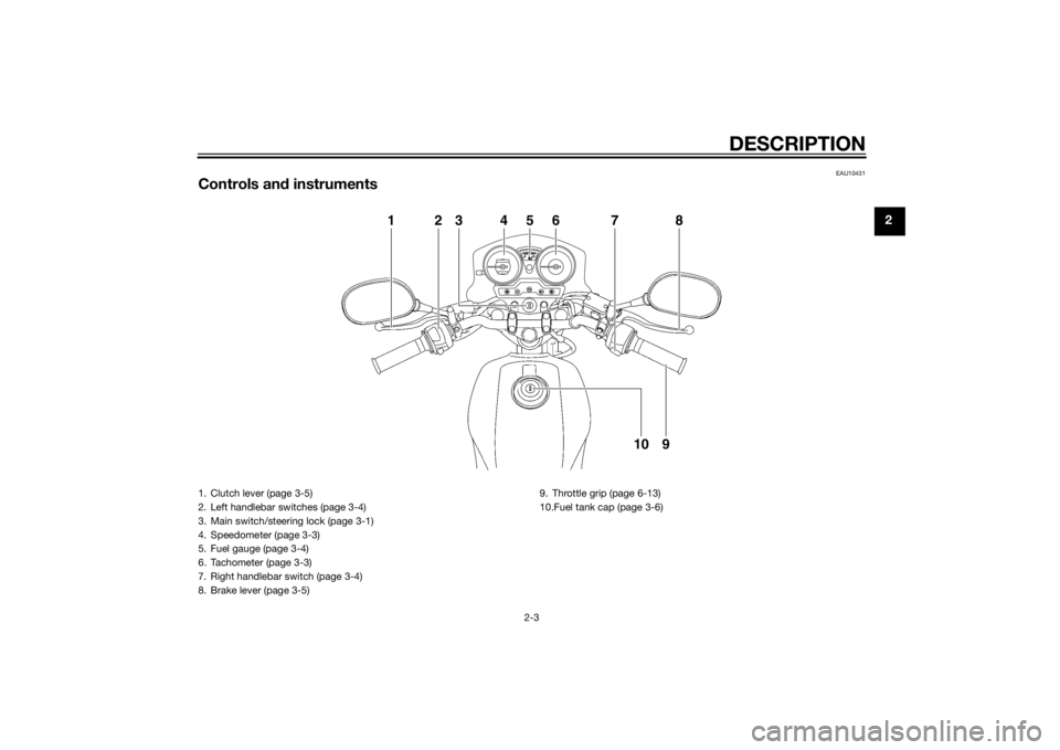
Controls and instruments
1
2
3
4
5
6
7
8
9
10
1. Clutch lever (page 3-5)
2. Left handlebar switches (page 3-4)
3. Main switch/steering lock (page 3-1)
4. Speedometer (page 3-3)
5. Fuel gauge (page 3-4)
6. Tachometer (page 3-3)
7. Right handlebar switch (page 3-4)
8. Brake lever (page 3-5) 9. Throttle grip (page 6-13)
10.Fuel tank cap (page 3-6)
U51DE1E0.book Page 3 Thursday, August 29, 2013 4:41 PM
Page 20 of 84
INSTRUMENT AND CONTROL FUNCTIONS
3-5
3
EAU12821
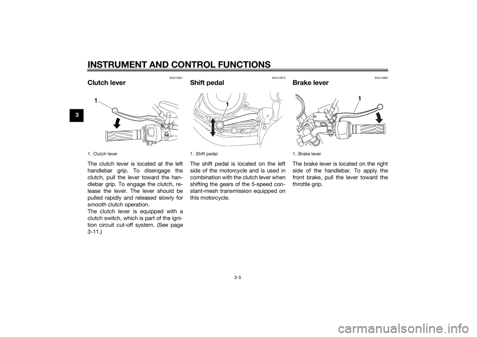
Clutch leverThe clutch lever is located at the left
handlebar grip. To disengage the
clutch, pull the lever toward the han-
dlebar grip. To engage the clutch, re-
lease the lever. The lever should be
pulled rapidly and released slowly for
smooth clutch operation.
The clutch lever is equipped with a
clutch switch, which is part of the igni-
tion circuit cut-off system. (See page
3-11.)
EAU12872
Shift pedalThe shift pedal is located on the left
side of the motorcycle and is used in
combination with the clutch lever when
shifting the gears of the 5-speed con-
stant-mesh transmission equipped on
this motorcycle.
EAU12892
Brake leverThe brake lever is located on the right
side of the handlebar. To apply the
front brake, pull the lever toward the
throttle grip.
1. Clutch lever
1. Shift pedal
1
1. Brake lever
1
U51DE1E0.book Page 5 Thursday, August 29, 2013 4:41 PM
Page 24 of 84
INSTRUMENT AND CONTROL FUNCTIONS
3-9
3
EAU43151
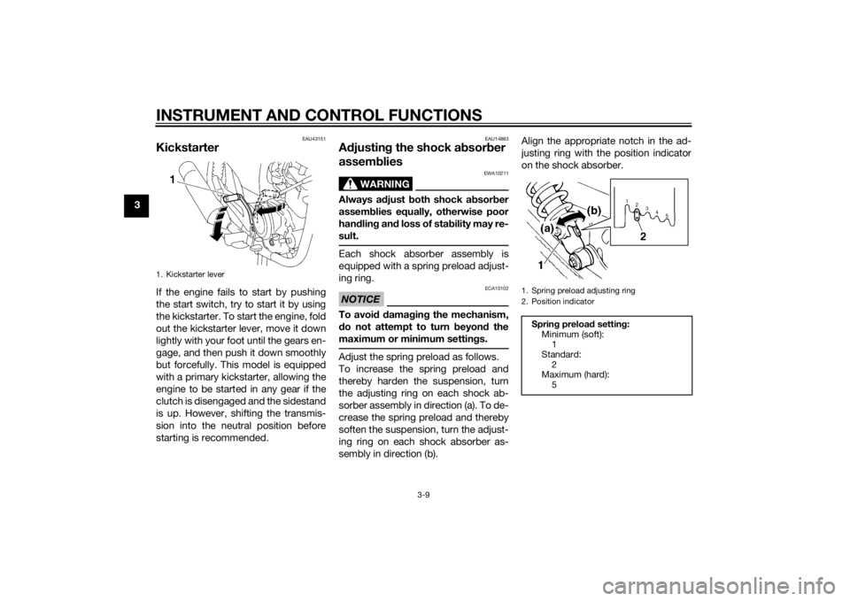
KickstarterIf the engine fails to start by pushing
the start switch, try to start it by using
the kickstarter. To start the engine, fold
out the kickstarter lever, move it down
lightly with your foot until the gears en-
gage, and then push it down smoothly
but forcefully. This model is equipped
with a primary kickstarter, allowing the
engine to be started in any gear if the
clutch is disengaged and the sidestand
is up. However, shifting the transmis-
sion into the neutral position before
starting is recommended.
EAU14883
Adjustin g the shock a bsorb er
assem blies
WARNING
EWA10211
Always a djust both shock ab sorber
assem blies equally, otherwise poor
han dlin g an d loss of sta bility may re-
sult.Each shock absorber assembly is
equipped with a spring preload adjust-
ing ring.NOTICE
ECA10102
To avoi d d amag ing the mechanism,
d o not attempt to turn b eyond the
maximum or minimum settin gs.Adjust the spring preload as follows.
To increase the spring preload and
thereby harden the suspension, turn
the adjusting ring on each shock ab-
sorber assembly in direction (a). To de-
crease the spring preload and thereby
soften the suspension, turn the adjust-
ing ring on each shock absorber as-
sembly in direction (b). Align the appropriate notch in the ad-
justing ring with the position indicator
on the shock absorber.
1. Kickstarter lever
1. Spring preload adjusting ring
2. Position indicatorSprin
g preloa d setting :
Minimum (soft): 1
Standard:
2
Maximum (hard): 5
U51DE1E0.book Page 9 Thursday, August 29, 2013 4:41 PM
Page 26 of 84

INSTRUMENT AND CONTROL FUNCTIONS
3-11
3
EAU43163
Ig nition circuit cut-off systemThe ignition circuit cut-off system
(comprising the sidestand switch,
clutch switch and neutral switch) has
the following functions.
It prevents starting when the
transmission is in gear and the
sidestand is up, but the clutch le-
ver is not pulled.
It prevents starting when the
transmission is in gear and the
clutch lever is pulled, but the side-
stand is still down.
It cuts the running engine when
the transmission is in gear and the
sidestand is moved down.
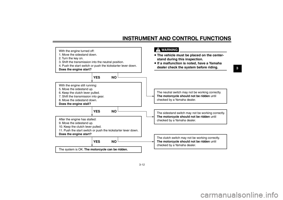
Periodically check the operation of the
ignition circuit cut-off system accord-
ing to the following procedure.U51DE1E0.book Page 11 Thursday, August 29, 2013 4:41 PM
Page 27 of 84
INSTRUMENT AND CONTROL FUNCTIONS
3-12
3
With the engine turned off:
1. Move the sidestand down.
2. Turn the key on.
3. Shift the transmission into the neutral position.
4. Push the start switch or push the kickstarter lever down.
Does the engine start?
With the engine still running:
5. Move the sidestand up.
6. Keep the clutch lever pulled.
7. Shift the transmission into gear.
8. Move the sidestand down.
Does the engine stall?
After the engine has stalled:
9. Move the sidestand up.
10. Keep the clutch lever pulled.
11. Push the start switch or push the kickstarter lever down.
Does the engine start?
The system is OK. The motorcycle can be ridden. The sidestand switch may not be working correctly.
The motorcycle should not be ridden
until
checked by a Yamaha dealer.
The clutch switch may not be working correctly.
The motorcycle should not be ridden until
checked by a Yamaha dealer.
YES NO YES NO YES NO
The neutral switch may not be working correctly.
The motorcycle should not be ridden until
checked by a Yamaha dealer.• The vehicle must be placed on the center-
stand during this inspection.• If a malfunction is noted, have a Yamaha
dealer check the system before riding.
WARNING
U51DE1E0.book Page 12 Thursday, August 29, 2013 4:41 PM
Page 28 of 84
FOR YOUR SAFETY – PRE-OPERATION CHECKS
4-1
4
EAU15598
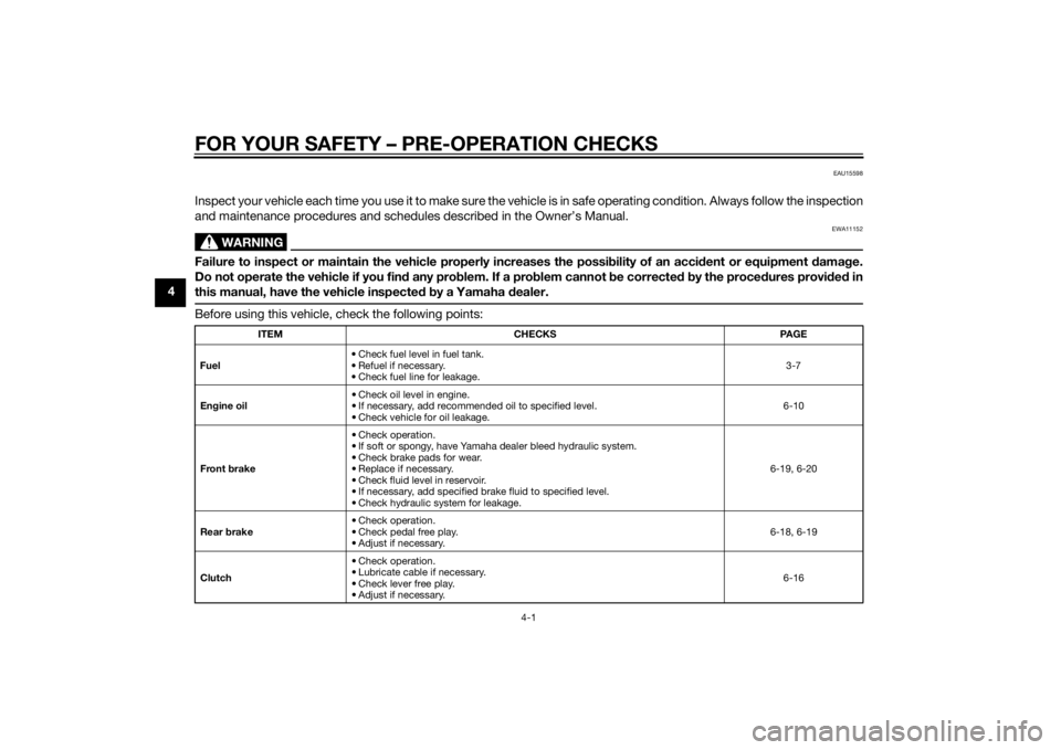
Inspect your vehicle each time you use it to make sure the vehicle is in safe operating condition. Always follow the inspection
and maintenance procedures and schedules described in the Owner’s Manual.
WARNING
EWA11152
Failure to inspect or maintain the vehicle properly increases the possibility of an acci dent or equipment damag e.
Do not operate the vehicle if you fin d any pro blem. If a pro blem cannot be corrected b y the proce dures provi ded in
this manual, have the vehicle inspecte d b y a Yamaha dealer.Before using this vehicle, check the following points:
ITEM CHECKS PAGE
Fuel • Check fuel level in fuel tank.
• Refuel if necessary.
• Check fuel line for leakage. 3-7
En gine oil • Check oil level in engine.
• If necessary, add recommended oil to specified level.
• Check vehicle for oil leakage. 6-10
Front brake • Check operation.
• If soft or spongy, have Yamaha dealer bleed hydraulic system.
• Check brake pads for wear.
• Replace if necessary.
• Check fluid level in reservoir.
• If necessary, add specified brake fluid to specified level.
• Check hydraulic system for leakage. 6-19, 6-20
Rear brake • Check operation.
• Check pedal free play.
• Adjust if necessary. 6-18, 6-19
Clutch • Check operation.
• Lubricate cable if necessary.
• Check lever free play.
• Adjust if necessary. 6-16
U51DE1E0.book Page 1 Thursday, August 29, 2013 4:41 PM
Page 29 of 84

FOR YOUR SAFETY – PRE-OPERATION CHECKS
4-2
4
Throttle grip • Make sure that operation is smooth.
• Check throttle grip free play.
• If necessary, have Yamaha dealer adjust throttle grip free play and lubricate ca-
ble and grip housing. 6-13, 6-24
Control ca bles • Make sure that operation is smooth.
• Lubricate if necessary.
6-24
Drive chain • Check chain slack.
• Adjust if necessary.
• Check chain condition.
• Lubricate if necessary. 6-21, 6-23
Wheels an d tires • Check for damage.
• Check tire condition and tread depth.
• Check air pressure.
• Correct if necessary. 6-14, 6-16
Shift pe dal • Make sure that operation is smooth.
• Correct if necessary.
6-18
Brake pe dal • Make sure that operation is smooth.
• Lubricate pedal pivoting point if necessary. 6-25
Brake an d clutch levers • Make sure that operation is smooth.
• Lubricate lever pivoting points if necessary. 6-24
Centerstan d, si destan d • Make sure that operation is smooth.
• Lubricate pivots if necessary.
6-25
Chassis fasteners • Make sure that all nuts, bolts and screws are properly tightened.
• Tighten if necessary.
—
Instruments, li ghts, si gnals
an d switches • Check operation.
• Correct if necessary.
—
Si destan d switch • Check operation of ignition circuit cut-off system.
• If system is not working correctly, have Yamaha dealer check vehicle.
3-10
ITEM CHECKS PAGE
U51DE1E0.book Page 2 Thursday, August 29, 2013 4:41 PM
Page 30 of 84
OPERATION AND IMPORTANT RIDING POINTS
5-1
5
EAU15952
Read the Owner’s Manual carefully to
become familiar with all controls. If
there is a control or function you do not
understand, ask your Yamaha dealer.
WARNING
EWA10272
Failure to familiarize yourself with
the controls can lead to loss of con-
trol, which coul d cause an acci dent
or injury.
EAU45311
TIPThis model is equipped with a lean an-
gle sensor to stop the engine in case of
a turnover. To start the engine after a
turnover, be sure to turn the main
switch to “OFF” and then to “ON”. Fail-
ing to do so will prevent the engine
from starting even though the engine
will crank when pushing the start
switch.
EAU43187
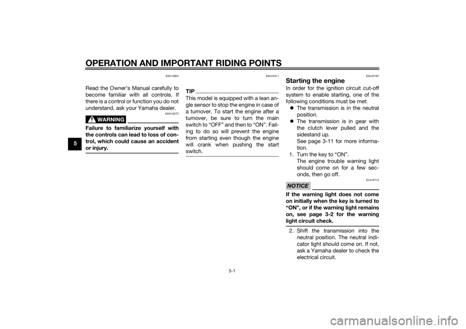
Startin g the en gineIn order for the ignition circuit cut-off
system to enable starting, one of the
following conditions must be met:
The transmission is in the neutral
position.
The transmission is in gear with
the clutch lever pulled and the
sidestand up.
See page 3-11 for more informa-
tion.
1. Turn the key to “ON”. The engine trouble warning light
should come on for a few sec-
onds, then go off.NOTICE
ECA16712
If the warnin g li ght does not come
on initially when the key is turne d to
“ON”, or if the warnin g li ght remains
on, see pa ge 3-2 for the warnin g
li g ht circuit check.2. Shift the transmission into the
neutral position. The neutral indi-
cator light should come on. If not,
ask a Yamaha dealer to check the
electrical circuit.
U51DE1E0.book Page 1 Thursday, August 29, 2013 4:41 PM
Page 31 of 84
OPERATION AND IMPORTANT RIDING POINTS
5-2
5
3. Start the engine by pushing the
start switch or by pushing the
kickstarter lever down.
If the engine fails to start when us-
ing the start switch, release it, wait
a few seconds, and then try again.
Each starting attempt should be
as short as possible to preserve
the battery. Do not crank the en-
gine more than 10 seconds on any
one attempt. If the engine does
not start with the starter motor, try
using the kickstarter.
NOTICE
ECA11043
For maximum en gine life, never ac-
celerate har d when the en gine is
col d!
EAU16672
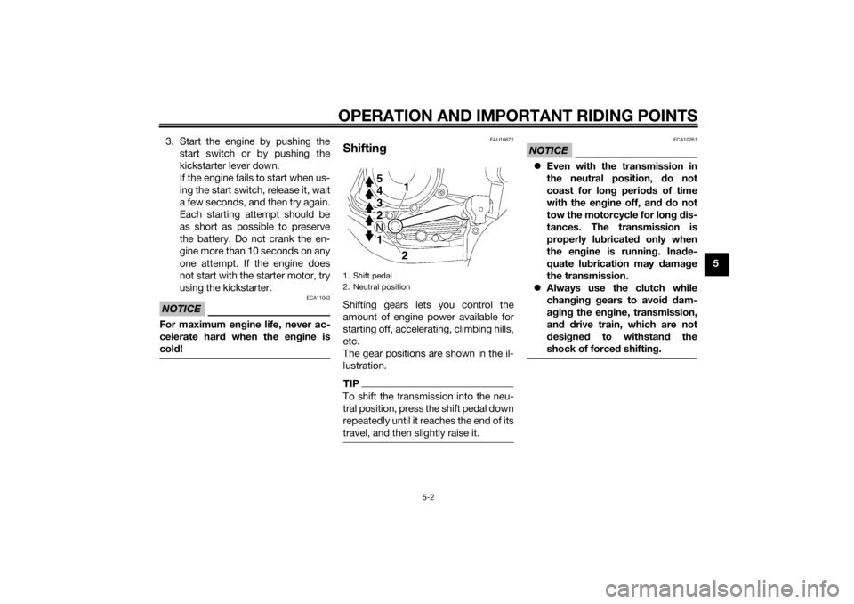
Shiftin gShifting gears lets you control the
amount of engine power available for
starting off, accelerating, climbing hills,
etc.
The gear positions are shown in the il-
lustration.TIPTo shift the transmission into the neu-
tral position, press the shift pedal down
repeatedly until it reaches the end of its
travel, and then slightly raise it.
NOTICE
ECA10261
Even with the transmission in
the neutral position, d o not
coast for lon g period s of time
with the en gine off, an d d o not
tow the motorcycle for lon g d is-
tances. The transmission is
properly lu bricated only when
the en gine is runnin g. Ina de-
quate lu brication may d amage
the transmission.
Always use the clutch while
chan gin g g ears to avoi d d am-
a g in g the en gine, transmission,
an d d rive train, which are not
d esi gne d to withstan d the
shock of force d shiftin g.
1. Shift pedal
2. Neutral position
U51DE1E0.book Page 2 Thursday, August 29, 2013 4:41 PM