warning YAMAHA YFM700R 2021 User Guide
[x] Cancel search | Manufacturer: YAMAHA, Model Year: 2021, Model line: YFM700R, Model: YAMAHA YFM700R 2021Pages: 150, PDF Size: 3.63 MB
Page 32 of 150
5-7
5The brake pedal is located on the right side of the
ATV. To apply the rear brake, push down on the
brake pedal.
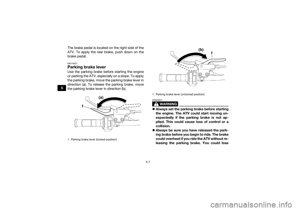
EBU18521Parking brake leverUse the parking brake before starting the engine
or parking the ATV, especially on a slope. To apply
the parking brake, move the parking brake lever in
direction (a). To release the parking brake, move
the parking brake lever in direction (b).
WARNING
EWB00221
Always set the parking brake before starting
the engine. The ATV could start moving un-
expectedly if the parking brake is not ap-
plied. This could cause loss of control or a
collision.
Always be sure you have released the park-
ing brake before you begin to ride. The brake
could overheat if you ride the ATV without re-
leasing the parking brake. You could lose
1. Parking brake lever (locked position)
1. Parking brake lever (unlocked position)
UBCX61E0.book Page 7 Friday, January 22, 2021 1:54 PM
Page 34 of 150
5-9
5
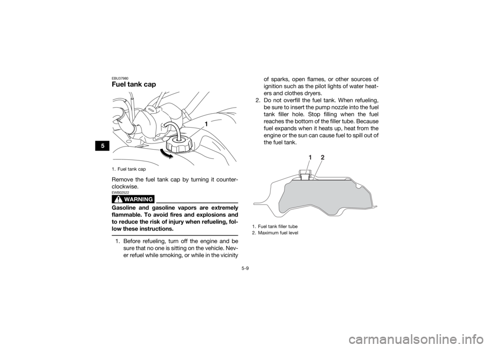
EBU37980Fuel tank capRemove the fuel tank cap by turning it counter-
clockwise.
WARNING
EWB02522Gasoline and gasoline vapors are extremely
flammable. To avoid fires and explosions and
to reduce the risk of injury when refueling, fol-
low these instructions. 1. Before refueling, turn off the engine and besure that no one is sitting on the vehicle. Nev-
er refuel while smoking, or while in the vicinity of sparks, open flames, or other sources of
ignition such as the pilot lights of water heat-
ers and clothes dryers.
2. Do not overfill the fuel tank. When refueling, be sure to insert the pump nozzle into the fuel
tank filler hole. Stop filling when the fuel
reaches the bottom of the filler tube. Because
fuel expands when it heats up, heat from the
engine or the sun can cause fuel to spill out of
the fuel tank.1. Fuel tank cap
1
1. Fuel tank filler tube
2. Maximum fuel level
1
2
UBCX61E0.book Page 9 Friday, January 22, 2021 1:54 PM
Page 35 of 150
![YAMAHA YFM700R 2021 User Guide 5-10
5
3. Wipe up any spilled fuel immediately.
NOTICE: Immediately wipe off spilled fuel
with a clean, dry, soft cloth, since fuel may
deteriorate painted surfaces or plastic
parts.
[ECB00982]
4. T YAMAHA YFM700R 2021 User Guide 5-10
5
3. Wipe up any spilled fuel immediately.
NOTICE: Immediately wipe off spilled fuel
with a clean, dry, soft cloth, since fuel may
deteriorate painted surfaces or plastic
parts.
[ECB00982]
4. T](/img/51/53742/w960_53742-34.png)
5-10
5
3. Wipe up any spilled fuel immediately.
NOTICE: Immediately wipe off spilled fuel
with a clean, dry, soft cloth, since fuel may
deteriorate painted surfaces or plastic
parts.
[ECB00982]
4. Turn the fuel tank cap fully clockwise to make sure it is securely closed.EBU38651FuelMake sure there is sufficient gasoline in the tank
before starting off. Refuel if necessary.
WARNING
EWB02532Gasoline is poisonous and can cause injury or
death. Handle gasoline with care. Never siphon
gasoline by mouth. If you should swallow some
gasoline or inhale a lot of gasoline vapor, or get
some gasoline in your eyes, see your doctor
immediately. If gasoline spills on your skin,
wash with soap and water. If gasoline spills on
your clothing, change your clothes.
TIPConfirm the gasoline pump nozzle has the same
fuel identification mark. Recommended fuel:Regular unleaded gasoline (Gasohol [E10]
acceptable)
Fuel tank capacity: 11 L (2.9 US gal, 2.4 Imp.gal)
Fuel reserve amount: 1.6 L (0.42 US gal, 0.35 Imp.gal)1. EN228 fuel identification mark
1
E5
E10
UBCX61E0.book Page 10 Friday, January 22, 2021 1:54 PM
Page 37 of 150

5-12
5
To install the seat
Fit the slot in the seat onto the projection on the
fuel tank, insert the projection on the front of the
seat into the seat holder, and then push on the
seat at the rear. Make sure that the seat is securely
fitted.
EBU30055Front shock absorbers The shock absorber spring preload, rebound
damping force, and compression damping force
(fast and slow compression damping) can be ad-
justed.
WARNING
EWB02492
Suspension components become hot during
operation. Never touch the compression
damping force adjusting bolt and screw, the
rebound damping force adjusting screw or
the oil reservoir with your bare hand or skin
until suspension components have cooled.
Always adjust the shock absorber assem-
blies on the left and right side to the same
setting. Uneven adjustment can cause poor
handling and loss of stability, which could
lead to an accident. Notes on adjusting the suspension
A special wrench can be obtained at a Yamaha
dealer to make the spring preload adjustment.
When adjusting the damping force settings, turn
the adjuster in direction (a) until it stops, and
then count the turns or clicks in direction (b).
Although a damping force adjuster may turn or
click beyond the stated minimum settings, such
adjustments are ineffective and may damage
the suspension.
1. Slot
2. Projection
3. Seat holder
1
2
3
2
UBCX61E0.book Page 12 Friday, January 22, 2021 1:54 PM
Page 41 of 150
5-16
5
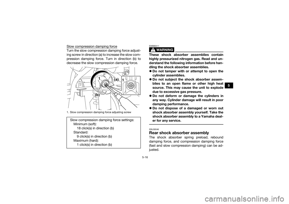
Slow compression damping force
Turn the slow compression damping force adjust-
ing screw in direction (a) to increase the slow com-
pression damping force. Turn in direction (b) to
decrease the slow compression damping force.
WARNING
EWB00411These shock absorber assemblies contain
highly pressurized nitrogen gas. Read and un-
derstand the following information before han-
dling the shock absorber assemblies.
Do not tamper with or attempt to open the
cylinder assemblies.
Do not subject the shock absorber assem-
blies to an open flame or other high heat
source. This may cause the unit to explode
due to excessive gas pressure.
Do not deform or damage the cylinders in
any way. Cylinder damage will result in poor
damping performance.
Do not dispose of a damaged or worn out
shock absorber assembly yourself. Take the
shock absorber assembly to a Yamaha deal-
er for any service. EBU30046Rear shock absorber assemblyThe shock absorber spring preload, rebound
damping force, and compression damping force
(fast and slow compression damping) can be ad-
justed.
1. Slow compression damping force adjusting screwSlow compression damping force settings:
Minimum (soft):18 click(s) in direction (b)
Standard: 9 click(s) in direction (b)
Maximum (hard): 1 click(s) in direction (b)
1 (a)
(b)
1
UBCX61E0.book Page 16 Friday, January 22, 2021 1:54 PM
Page 42 of 150
5-17
5
WARNING
EWB02681Suspension components become hot during
operation. Never touch the compression
damping force adjusting bolt and screw, the
rebound damping force adjusting screw or the
oil reservoir with your bare hand or skin until
the suspension components have cooled. Notes on adjusting the suspension
A special wrench can be obtained at a Yamaha
dealer to make the spring preload adjustment.
When adjusting the damping force settings, turn
the adjuster in direction (a) until it stops, and
then count the turns or clicks in direction (b).
Although a damping force adjuster may turn or
click beyond the stated minimum settings, such
adjustments are ineffective and may damage
the suspension.NOTICEECB00091Never turn an adjusting mechanism beyond
the minimum and maximum settings.
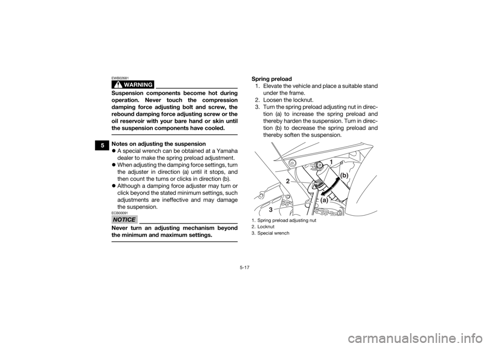
Spring preload
1. Elevate the vehicle and place a suitable stand under the frame.
2. Loosen the locknut.
3. Turn the spring preload adjusting nut in direc- tion (a) to increase the spring preload and
thereby harden the suspension. Turn in direc-
tion (b) to decrease the spring preload and
thereby soften the suspension.1. Spring preload adjusting nut
2. Locknut
3. Special wrench
1
(b)
(a)
2
3
UBCX61E0.book Page 17 Friday, January 22, 2021 1:54 PM
Page 45 of 150
5-20
5
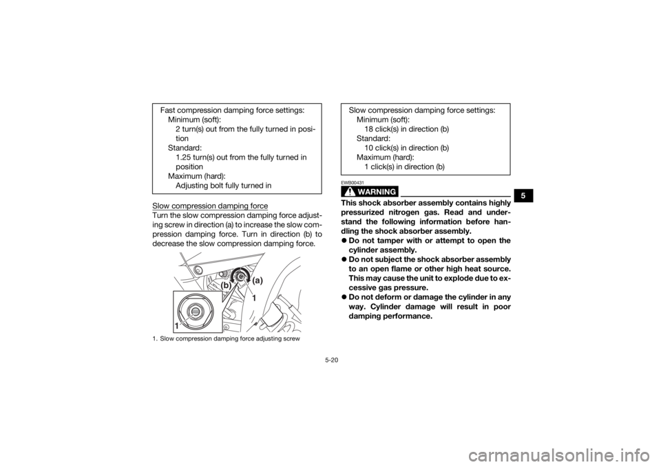
Slow compression damping force
Turn the slow compression damping force adjust-
ing screw in direction (a) to increase the slow com-
pression damping force. Turn in direction (b) to
decrease the slow compression damping force.
WARNING
EWB00431This shock absorber assembly contains highly
pressurized nitrogen gas. Read and under-
stand the following information before han-
dling the shock absorber assembly.
Do not tamper with or attempt to open the
cylinder assembly.
Do not subject the shock absorber assembly
to an open flame or other high heat source.
This may cause the unit to explode due to ex-
cessive gas pressure.
Do not deform or damage the cylinder in any
way. Cylinder damage will result in poor
damping performance.
Fast compression damping force settings:
Minimum (soft):2 turn(s) out from the fully turned in posi-
tion
Standard: 1.25 turn(s) out from the fully turned in
position
Maximum (hard): Adjusting bolt fully turned in
1. Slow compression damping force adjusting screw
1
(b)
(a)
1
Slow compression damping force settings:
Minimum (soft):18 click(s) in direction (b)
Standard: 10 click(s) in direction (b)
Maximum (hard): 1 click(s) in direction (b)
UBCX61E0.book Page 20 Friday, January 22, 2021 1:54 PM
Page 47 of 150
6-1
6
EBU19203
PRE-OPERATION CHECKS
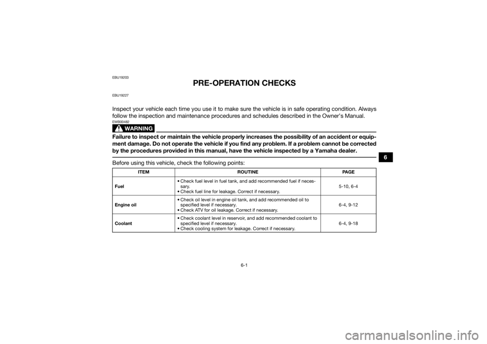
EBU19227Inspect your vehicle each time you use it to make sure the vehicle is in safe operating condition. Always
follow the inspection and maintenance procedures and schedules described in the Owner’s Manual.
WARNING
EWB00482Failure to inspect or maintain the vehicle properly increases the possibility of an accident or equip-
ment damage. Do not operate the vehicle if you find any problem. If a problem cannot be corrected
by the procedures provided in this manual, have the vehicle inspected by a Yamaha dealer. Before using this vehicle, check the following points:
ITEMROUTINE PAGE
Fuel • Check fuel level in fuel tank,
and add recommended fuel if neces-
sary.
• Check fuel line for leakage. Correct if necessary. 5-10, 6-4
Engine oil • Check oil level in engine oil tank, and add recommended oil to
specified level if necessary.
• Check ATV for oil leakage. Correct if necessary. 6-4, 9-12
Coolant • Check coolant level in reservoir, and add recommended coolant to
specified level if necessary.
• Check cooling system for leakage. Correct if necessary. 6-4, 9-18
UBCX61E0.book Page 1 Friday, January 22, 2021 1:54 PM
Page 51 of 150

6-5
6
Brake operation
Test the brakes at slow speed after starting out to
make sure they are working properly. If the brakes
do not provide proper braking performance,
check the brake pads for wear. (See page 9-29.)
EBU19762Throttle leverCheck the operation of the throttle lever. It must
open smoothly and spring back to the idle position
when released. Have a Yamaha dealer correct if
necessary.EBU19771Drive chainCheck the condition of the drive chain and check
the drive chain slack. Lubricate and adjust the
drive chain as necessary. (See page 9-38.)EBU1979ATiresCheck tire pressure regularly to make sure it is at
the recommended specifications. Also check for
wear and damage. Tire pressure
Use a tire pressure gauge to check and adjust tire
air pressure when the tires are cold. The tire air
pressure must be equal on both sides.
WARNING! Operation of this vehicle with im- proper tire pressure may cause severe injury or
death from loss of control or rollover. Tire
pressure below the minimum specified could
also cause the tire to dislodge from the rim un-
der severe riding conditions.
[EWB02542]
Recommended tire pressure: Front27.5 kPa (0.275 kgf/cm², 4.0 psi)
Rear 27.5 kPa (0.275 kgf/cm², 4.0 psi)
Minimum tire pressure: Front24.5 kPa (0.245 kgf/cm², 3.6 psi)
Rear 24.5 kPa (0.245 kgf/cm², 3.6 psi)
Maximum tire seating pressure: Front250 kPa (2.5 kgf/cm², 36 psi)
Rear 250 kPa (2.5 kgf/cm², 36 psi)
UBCX61E0.book Page 5 Friday, January 22, 2021 1:54 PM
Page 53 of 150

6-7
6
Aftermarket tires and rims
The tires and rims that came with your ATV were
designed to match the performance capabilities
and to provide the best combination of handling,
braking, and comfort. Other tires, rims, sizes, and
combinations may not be appropriate.
WARNING
EWB02552Use of improper tires on this ATV may cause
loss of control, increasing your risk of an acci-
dent.
EBU19841Chassis fastenersMake sure that all nuts, bolts and screws are
properly tightened.EBU19851Instruments, lights and switchesCheck that all instruments, lights and switches are
working properly. Correct if necessary.
Front:
Manufacturer/model:MAXXIS/MS13
Size: AT22 x 7-10
Rear: Manufacturer/model:MAXXIS/M976Y
Size: AT20 x 10-9
UBCX61E0.book Page 7 Friday, January 22, 2021 1:54 PM