warning YAMAHA YFM700R 2021 Service Manual
[x] Cancel search | Manufacturer: YAMAHA, Model Year: 2021, Model line: YFM700R, Model: YAMAHA YFM700R 2021Pages: 150, PDF Size: 3.63 MB
Page 80 of 150

8-19
8Test your brakes after leaving the water. If neces-
sary, apply them several times to let friction dry
out the linings. Do not continue to ride your ATV
without verifying that you have regained proper
braking ability. WARNING! Wet brakes may have
reduced stopping ability, which could cause
loss of control.
[EWB02622]
After riding your ATV in water, be sure to drain the
trapped water by removing the check hose at the
bottom of the air filter case. NOTICE: Undrained
water can cause damage or improper opera-
tion.
[ECB00842]
Wash the ATV in fresh water if it has been operat-
ed in salt water or muddy conditions.
UBCX61E0.book Page 19 Friday, January 22, 2021 1:54 PM
Page 81 of 150

8-20
8
RIDING OVER ROUGH TERRAIN
WARNING
EWB01652Riding improperly over obstacles could cause
loss of control or a collision. Before operating
in a new area, check for obstacles. Never at-
tempt to ride over large obstacles, such as
large rocks or fallen trees. When you go over
obstacles, always follow proper procedures as
described in the Owner’s Manual. Riding over rough terrain should be done with
caution. Look out for obstacles which could cause
damage to the ATV or could lead to an upset or accident. Be sure to keep your feet firmly mounted
on the footrests at all times. Avoid jumping the
ATV as loss of control and damage to the ATV may
result.
SLIDING AND SKIDDING
WARNING
EWB01663Skidding or sliding improperly may cause you
to lose control of this ATV. You may also regain
traction unexpectedly, which may cause the
ATV to overturn.
Learn to safely control skidding or sliding by
practicing at low speeds and on level,
smooth terrain.
On extremely slippery surfaces, such as ice,
go slowly and be very cautious in order to re-
duce the chance of skidding or sliding out of
control. Care should be used when riding on loose or slip-
pery surfaces since the ATV may slide. If unex-
pected and uncorrected, sliding could lead to an
accident.
1. Air filter case check hose
1
UBCX61E0.book Page 20 Friday, January 22, 2021 1:54 PM
Page 84 of 150

9-1
9
EBU28789
PERIODIC MAINTENANCE AND ADJUSTMENT
EBU21677Periodic inspection, adjustment, and lubrication
will keep your vehicle in the safest and most effi-
cient condition possible. Safety is an obligation of
the vehicle owner and operator. The most impor-
tant points of vehicle inspection, adjustment, and
lubrication are explained on the following pages.
WARNING
EWB01842Failure to properly maintain the vehicle or per-
forming maintenance activities incorrectly may
increase your risk of injury or death during ser-
vice or while using the vehicle. If you are not fa-
miliar with vehicle service, have a Yamaha
dealer perform the service.
WARNING
EWB02563Turn off the engine when performing mainte-
nance unless otherwise specified.
A running engine has moving parts that can
catch on body parts or clothing and electri-
cal parts that can cause shocks or fires.
Running the engine while servicing can lead
to eye injury, burns, fire, or carbon monoxide
poisoning - possibly leading to death. See
page 3-6 for more information about carbon
monoxide.
WARNING
EWB02691Brake discs, calipers, drums, and linings can
become very hot during use. To avoid possible
burns, let brake components cool before
touching them. The intervals given in the periodic maintenance
charts should be considered as a general guide
under normal riding conditions. However, DE-
PENDING ON THE WEATHER, TERRAIN, GEO-
GRAPHICAL LOCATION, AND INDIVIDUAL USE,
THE MAINTENANCE INTERVALS MAY NEED TO
BE SHORTENED.
UBCX61E0.book Page 1 Friday, January 22, 2021 1:54 PM
Page 102 of 150

9-19
92. Wait for the engine to cool for an accurate
reading.
3. Look at the coolant level in the coolant reser- voir.
4. If the coolant is at or below the minimum level mark, remove the coolant reservoir cap.
WARNING! Remove only the coolant res-
ervoir cap. Never attempt to remove the
radiator cap when the engine is hot.
[EWB02672]
5. Add coolant to the maximum level mark, andthen install the reservoir cap. NOTICE: If
coolant is not available, use distilled water
or soft tap water instead. Do not use hard
water or salt water since they are harmful
to the engine. If water has been used in-
stead of coolant, replace it with coolant as
soon as possible, otherwise the cooling
system will not be protected against frost
and corrosion. If water has been added to
the coolant, have a Yamaha dealer check
the antifreeze content of the coolant as
soon as possible, otherwise the effective-
ness of the coolant will be reduced.
[ECB01012]
1. Maximum level mark
2. Minimum level mark
12
1. Coolant reservoir cap
1
UBCX61E0.book Page 19 Friday, January 22, 2021 1:54 PM
Page 103 of 150

9-20
9
EBU23546To change the coolant
WARNING
EWB01891Wait for the engine and radiator to cool before
removing the radiator cap. You could be
burned by hot fluid and steam blown out under
pressure. Always place a thick rag over the cap
when opening. Allow any remaining pressure
to escape before completely removing the cap. 1. Park the ATV on a level surface.
2. Remove panel A. (See page 9-10.)
3. Place a container under the engine, and thenremove the coolant drain bolt and its gasket. 4. Remove the radiator cap.
1. Coolant drain bolt
2. Gasket
1. Radiator cap
1
2
1
UBCX61E0.book Page 20 Friday, January 22, 2021 1:54 PM
Page 106 of 150

9-23
96. Remove the wing bolt and washer from the air
filter element.
7. Remove the sponge material from the air filter element frame. 8. Wash the sponge material gently but thor-
oughly in solvent. WARNING! Always use
parts cleaning solvent. Never use low-
flash-point solvents or gasoline because
the engine could catch fire or explode.
[EWB01943]
9. Squeeze the excess solvent out of the sponge material and let it dry. NOTICE: Do
not twist the sponge material when
squeezing it.
[ECB00442]
1. Air filter element
2. Washer
3. Wing bolt
3
2
1
1. Sponge material
2. Air filter element frame
2
1
UBCX61E0.book Page 23 Friday, January 22, 2021 1:54 PM
Page 108 of 150

9-25
915. Insert the air filter element into the air filter
case, and then tighten the wing bolt.
NOTICE: Make sure that the air filter ele-
ment is properly seated in the air filter
case. Never operate the engine with the air
filter element removed. Doing so would al-
low unfiltered air to enter the engine, caus-
ing rapid engine wear and possible engine
damage. Additionally, the fuel injection
system would be affected resulting in poor
engine performance and possible over-
heating.
[ECB00763]
16. Install the air filter case cover by hooking the holders onto the air filter case. 17. Install the seat.
TIPThe air filter element should be cleaned every 20–
40 hours. It should be cleaned and lubricated
more often if the ATV is operated in extremely
dusty areas. Each time the air filter element main-
tenance is performed, check the air inlet of the air
filter case for obstructions. Check the air filter
case rubber joint to the throttle body and the rub-
ber joint manifold fittings for an air-tight seal.
Tighten all fittings securely to avoid the possibility
of unfiltered air entering the engine. EBU30863Cleaning the spark arresterSelect a well-ventilated area free of combustible
materials and make sure the exhaust and muffler
are cool.
WARNING
EWB02342Always let the exhaust system cool prior to
touching exhaust components.
Do not start the engine with the spark arrester
removed. Sparks or exhaust particulate can
cause eye injury, burns, or start a fire.
1. Washer
1
UBCX61E0.book Page 25 Friday, January 22, 2021 1:54 PM
Page 112 of 150

9-29
91. Slide the rubber cover back.
2. Loosen the locknut.
3. To increase the throttle lever free play, turn
the throttle lever free play adjusting bolt in di-
rection (a). To decrease the throttle lever free
play, turn the adjusting bolt in direction (b).
4. Tighten the locknut.
5. Slide the rubber cover to its original position.
EBU24062Valve clearanceThe valve clearance changes with use, resulting in
improper air-fuel mixture and/or engine noise. To
prevent this from occurring, the valve clearance
must be adjusted by a Yamaha dealer at the inter-
vals specified in the periodic maintenance chart.EBU24082Adjusting the reverse lock release ca-
bleThe reverse lock release cable stretches with use,
which can result in improper function. Therefore,
the reverse lock release cable should be checked
and adjusted at the intervals specified in the peri-
odic maintenance chart.
EBU29602BrakesReplacement of brake components requires pro-
fessional knowledge. Brake service should be
performed by a Yamaha dealer.
WARNING
EWB02572Operating with improperly serviced or adjust-
ed brakes could lead to a loss in braking ability
and an accident. EBU24132Checking the front and rear brake padsThe front and rear brake pads must be checked
for wear at the intervals specified in the periodic
maintenance chart.EBU29561Front brake pads
Each brake pad is provided with wear indicator
grooves, which allow you to check the brake pad
wear without having to disassemble the brake. To
check the brake pad wear, check the wear indica-
tor grooves. If a brake pad has worn to the point
that the wear indicator grooves have almost dis-
appeared, have a Yamaha dealer replace the
brake pads as a set.
UBCX61E0.book Page 29 Friday, January 22, 2021 1:54 PM
Page 115 of 150
9-32
9
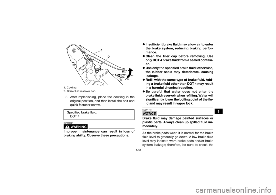
3. After replenishing, place the cowling in the
original position, and then install the bolt and
quick fastener screw.
WARNING
EWB02721Improper maintenance can result in loss of
braking ability. Observe these precautions:
Insufficient brake fluid may allow air to enter
the brake system, reducing braking perfor-
mance.
Clean the filler cap before removing. Use
only DOT 4 brake fluid from a sealed contain-
er.
Use only the specified brake fluid; otherwise,
the rubber seals may deteriorate, causing
leakage.
Refill with the same type of brake fluid. Add-
ing a brake fluid other than DOT 4 may result
in a harmful chemical reaction.
Be careful that water does not enter the
brake fluid reservoir when refilling. Water will
significantly lower the boiling point of the flu-
id and may result in vapor lock.
NOTICEECB01161Brake fluid may damage painted surfaces or
plastic parts. Always clean up spilled fluid im-
mediately. As the brake pads wear, it is normal for the brake
fluid level to gradually go down. A low brake fluid
level may indicate worn brake pads and/or brake
system leakage; therefore, be sure to check the
1. Cowling
2. Brake fluid reservoir capSpecified brake fluid:
DOT 4
1
2
UBCX61E0.book Page 32 Friday, January 22, 2021 1:54 PM
Page 118 of 150
9-35
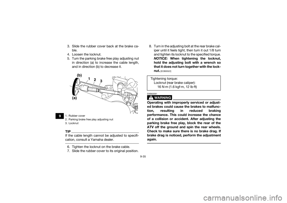
93. Slide the rubber cover back at the brake ca-
ble.
4. Loosen the locknut.
5. Turn the parking brake free play adjusting nut in direction (a) to increase the cable length,
and in direction (b) to decrease it.
TIPIf the cable length cannot be adjusted to specifi-
cation, consult a Yamaha dealer. 6. Tighten the locknut on the brake cable.
7. Slide the rubber cover to its original position. 8. Turn in the adjusting bolt at the rear brake cal-
iper until it feels tight, then turn it out 1/8 turn
and tighten its locknut to the specified torque.
NOTICE: When tightening the locknut,
hold the adjusting bolt with a wrench so
that it does not turn together with the lock-
nut.
[ECB00522]
WARNING
EWB02091Operating with improperly serviced or adjust-
ed brakes could cause the brakes to malfunc-
tion, resulting in reduced braking
performance. This could increase the chance
of a collision or accident. After adjusting the
parking brake free play, block the rear of the
ATV off the ground and spin the rear wheels.
Check to make sure there is no brake drag. If
brake drag is noticed, perform the adjustment
again.
1. Rubber cover
2. Parking brake free play adjusting nut
3. Locknut
1
(b)
(a) 2
3
Tightening torque:
Locknut (rear brake caliper):16 N·m (1.6 kgf·m, 12 lb·ft)
UBCX61E0.book Page 35 Friday, January 22, 2021 1:54 PM