fuel filter YAMAHA YFZ450R 2010 Owners Manual
[x] Cancel search | Manufacturer: YAMAHA, Model Year: 2010, Model line: YFZ450R, Model: YAMAHA YFZ450R 2010Pages: 154, PDF Size: 3.8 MB
Page 28 of 154

3-2
3
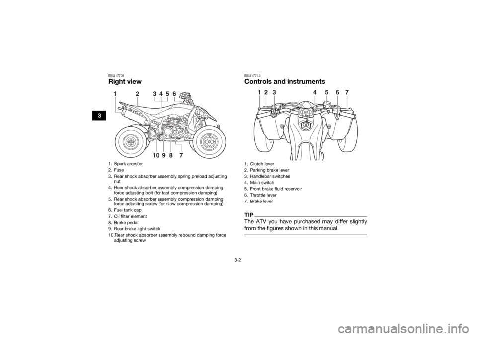
EBU17701Right view
EBU17713Controls and instrumentsTIPThe ATV you have purchased may differ slightly
from the figures shown in this manual.
1. Spark arrester
2. Fuse
3. Rear shock absorber assembly spring preload adjusting nut
4. Rear shock absorber assembly compression damping force adjusting bolt (for fast compression damping)
5. Rear shock absorber assembly compression damping force adjusting screw (for slow compression damping)
6. Fuel tank cap
7. Oil filter element
8. Brake pedal
9. Rear brake light switch
10.Rear shock absorber assembly rebound damping force adjusting screw
789
1
2
3
4
5
10
6
1. Clutch lever
2. Parking brake lever
3. Handlebar switches
4. Main switch
5. Front brake fluid reservoir
6. Throttle lever
7. Brake lever
2
1
3
6
5
4
7
U1TD61E0.book Page 2 Tuesday, July 8, 2014 11:30 AM
Page 114 of 154

8-25
815. Insert the air filter element into the air filter
case, and then tighten the wing bolt.
NOTICE: Make sure that the air filter ele-
ment is properly seated in the air filter
case. Never operate the engine with the air
filter element removed. Doing so would al-
low unfiltered air to enter the engine, caus-
ing rapid engine wear and possible engine
damage. Additionally, the fuel injection
system would be affected resulting in poor
engine performance and possible over-
heating.
[ECB00763]
16. Install the air filter case cover by hooking the holders onto the air filter case. 17. Install the seat.
TIPThe air filter element should be cleaned every 20–
40 hours. It should be cleaned and lubricated
more often if the ATV is operated in extremely
dusty areas. Each time the air filter element main-
tenance is performed, check the air inlet of the air
filter case for obstructions. Check the air filter
case rubber joint to the throttle body and the rub-
ber joint manifold fittings for an air-tight seal.
Tighten all fittings securely to avoid the possibility
of unfiltered air entering the engine. EBU30861Cleaning the spark arresterSelect a well-ventilated area free of combustible
materials and make sure the exhaust and muffler
are cool.
1. Remove the tailpipe cover by removing the bolts.
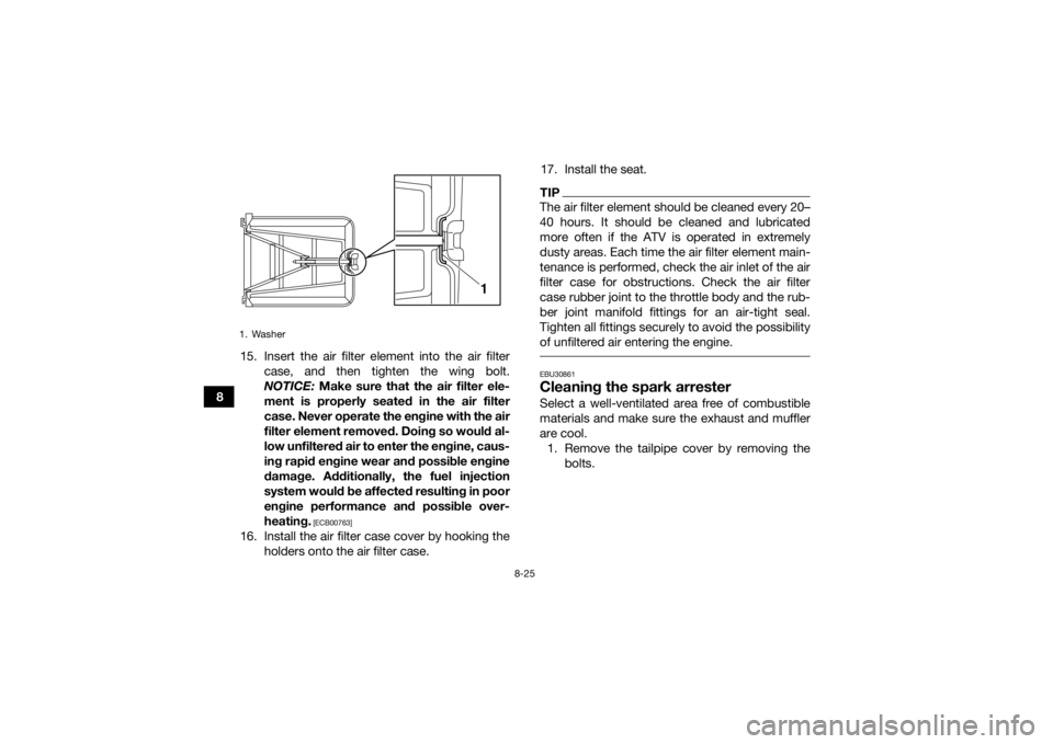
1. Washer
1
U1TD61E0.book Page 25 Tuesday, July 8, 2014 11:30 AM
Page 146 of 154

10-2
10
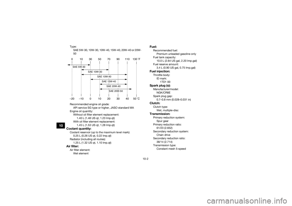
Type:SAE 5W-30, 10W-30, 10W-40, 15W-40, 20W-40 or 20W-
50
Recommended engine oil grade: API service SG type or higher, JASO standard MA
Engine oil quantity: Without oil filter element replacement: 1.40 L (1.48 US qt, 1.23 Imp.qt)
With oil filter element replacement: 1.45 L (1.53 US qt, 1.28 Imp.qt)Coolant quantity:Coolant reservoir (up to the maximum level mark):0.25 L (0.26 US qt, 0.22 Imp.qt)
Radiator (including all routes): 1.25 L (1.32 US qt, 1.10 Imp.qt)Air filter:Air filter element:Wet element
Fuel:Recommended fuel:Premium unleaded gasoline only
Fuel tank capacity:
10.0 L (2.64 US gal, 2.20 Imp.gal)
Fuel reserve amount: 3.4 L (0.90 US gal, 0.75 Imp.gal)Fuel injection:Throttle body:
ID mark: 1TD1 00Spark plug (s):Manufacturer/model:NGK/CR8E
Spark plug gap: 0.7–0.8 mm (0.028–0.031 in)Clutch:Clutch type:Wet, multiple-discTransmission:Primary reduction system:
Spur gear
Primary reduction ratio: 61/23 (2.652)
Secondary reduction system: Chain drive
Secondary reduction ratio:
38/14 (2.714)
Transmission type: Constant mesh 5-speed
0 10 30 50 70 90 110 130 �F
–20 –10 0 10 20 30 40 50 �CSAE 5W-30
SAE 10W-30
SAE 10W-40
SAE 15W-40
SAE 20W-40SAE 20W-50
U1TD61E0.book Page 2 Tuesday, July 8, 2014 11:30 AM
Page 152 of 154

12-1
12
INDEX
AAccessories and loading ................................................ 6-5
Air filter element, cleaning ............................................ 8-21BBattery .......................................................................... 8-42
Brake and clutch levers, checking and lubricating ...... 8-39
Brake fluid, changing ...................................................8-31
Brake fluid level, checking ........................................... 8-29
Brake lever ..................................................................... 4-6
Brake lever free play, checking the front ..................... 8-31
Brake light switches ..................................................... 8-33
Brake pads, checking the front and rear ..................... 8-28
Brake pedal .................................................................... 4-6
Brake pedal, checking and lubricating ........................ 8-39
Brake pedal height, checking ...................................... 8-32
Brakes .......................................................................... 8-28
Brakes, front and rear .................................................... 5-4CCables, checking and lubricating ................................. 8-38
Chassis fasteners ........................................................... 5-7
Cleaning ......................................................................... 9-1
Clutch lever .................................................................... 4-5
Clutch lever free play, adjusting ................................... 8-34
Coolant ................................................................. 5-4, 8-20
Coolant temperature warning light ................................. 4-2
Cowling and panels, removing and installing .............. 8-10DDrive chain ..................................................................... 5-5
Drive chain, lubricating ................................................ 8-37 Drive chain slack .......................................................... 8-35
EEngine break-in .............................................................. 6-4
Engine oil ....................................................................... 5-4
Engine oil and oil filter element .................................... 8-14
Engine, start ................................................................... 6-1
Engine stop switch ......................................................... 4-3
Engine trouble warning light .......................................... 4-3FFuel ........................................................................ 4-9, 5-4
Fuel level warning light ................................................... 4-3
Fuel tank cap ................................................................. 4-8
Fuse, replacing ............................................................. 8-45HHandlebar position, adjusting ...................................... 4-24
Handlebar switches ....................................................... 4-3
Headlight beam, adjusting ........................................... 8-48
Headlight bulb, replacing ............................................. 8-45IIdentification numbers ................................................. 11-1
Indicator light and warning lights ................................... 4-2
Instruments, lights and switches ................................... 5-8LLabel locations ............................................................... 1-1
Light switch .................................................................... 4-4MMain switch .................................................................... 4-1
Maintenance and lubrication chart ................................ 8-5
Maintenance chart, emission control system ................ 8-3
U1TD61E0.book Page 1 Tuesday, July 8, 2014 11:30 AM