lock YAMAHA YXZ1000R SS 2017 User Guide
[x] Cancel search | Manufacturer: YAMAHA, Model Year: 2017, Model line: YXZ1000R SS, Model: YAMAHA YXZ1000R SS 2017Pages: 208, PDF Size: 4.79 MB
Page 49 of 208
4-11
4
4. Push the “SELECT” button, and the mi-nute digits will start flashing.
5. Push the “RESET” button to set the minu- tes.
6. Push the “SELECT” button, and then re-
lease it to start the clock.
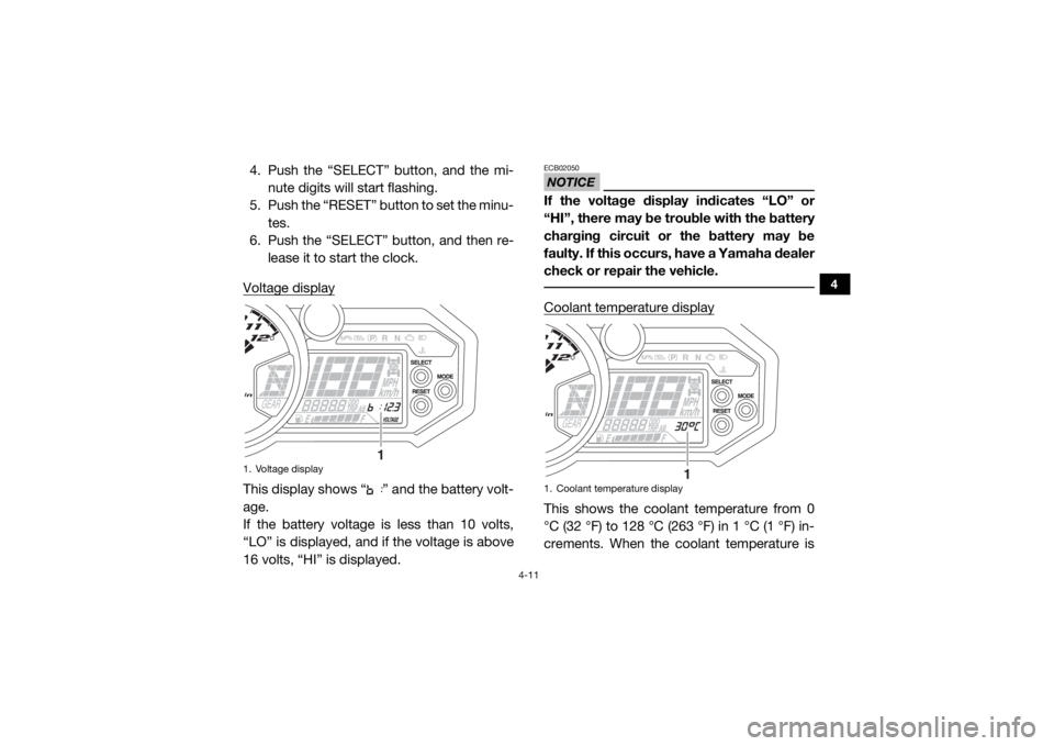
Voltage displayThis display shows “ ” and the battery volt-
age.
If the battery voltage is less than 10 volts,
“LO” is displayed, and if the voltage is above
16 volts, “HI” is displayed.
NOTICEECB02050If the voltage display indicates “LO” or
“HI”, there may be trouble with the battery
charging circuit or the battery may be
faulty. If this occurs, have a Yamaha dealer
check or repair the vehicle. Coolant temperature displayThis shows the coolant temperature from 0
°C (32 °F) to 128 °C (263 °F) in 1 °C (1 °F) in-
crements. When the coolant temperature is
1. Voltage display
1
1. Coolant temperature display
1
U2HC7ME0.book Page 11 Tuesday, April 19, 2016 10:33 AM
Page 55 of 208
4-17
4
Set the switch to “ ” to turn off the head-
lights and taillight.NOTICEECB02060Do not use the headlights with the engine
turned off for an extended period of time.
The battery may discharge to the point
that the starter motor will not operate
properly. If this should happen, remove the
battery and recharge it.
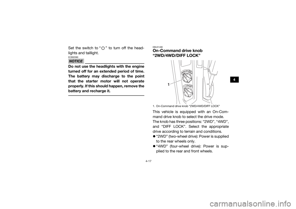
EBU31400On-Command drive knob
“2WD/4WD/DIFF LOCK”This vehicle is equipped with an On-Com-
mand drive knob to select the drive mode.
The knob has three positions: “2WD”, “4WD”,
and “DIFF LOCK”. Select the appropriate
drive according to terrain and conditions.
“2WD” (two-wheel drive): Power is supplied
to the rear wheels only.
“4WD” (four-wheel drive): Power is sup-
plied to the rear and front wheels.1. On-Command drive knob “2WD/4WD/DIFF LOCK”
1
U2HC7ME0.book Page 17 Tuesday, April 19, 2016 10:33 AM
Page 56 of 208
4-18
4
“DIFF LOCK” (four-wheel drive with the dif-
ferential gear locked): Power is supplied to
the rear and front wheels with the differen-
tial gear locked. Unlike the “4WD” mode, all
wheels turn at the same speed regardless
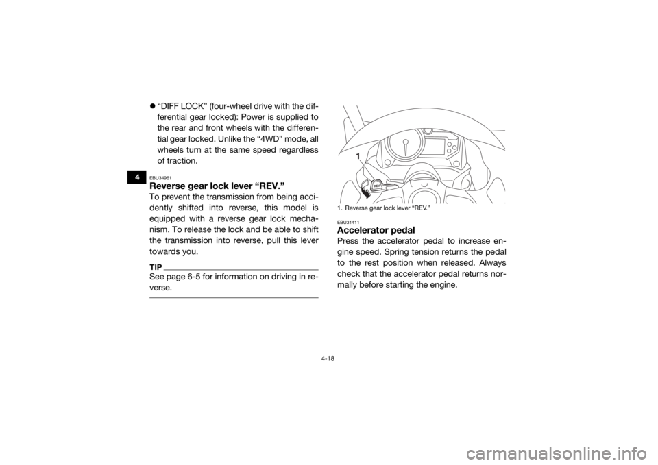
of traction.EBU34961Reverse gear lock lever “REV.”To prevent the transmission from being acci-
dently shifted into reverse, this model is
equipped with a reverse gear lock mecha-
nism. To release the lock and be able to shift
the transmission into reverse, pull this lever
towards you.TIPSee page 6-5 for information on driving in re-
verse.
EBU31411Accelerator pedalPress the accelerator pedal to increase en-
gine speed. Spring tension returns the pedal
to the rest position when released. Always
check that the accelerator pedal returns nor-
mally before starting the engine.1. Reverse gear lock lever “REV.”
1
U2HC7ME0.book Page 18 Tuesday, April 19, 2016 10:33 AM
Page 59 of 208
4-21
4
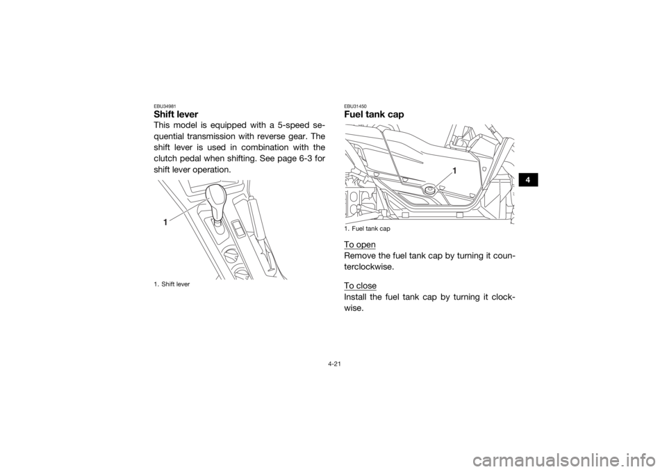
EBU34981Shift leverThis model is equipped with a 5-speed se-
quential transmission with reverse gear. The
shift lever is used in combination with the
clutch pedal when shifting. See page 6-3 for
shift lever operation.
EBU31450Fuel tank capTo openRemove the fuel tank cap by turning it coun-
terclockwise.
To closeInstall the fuel tank cap by turning it clock-
wise.
1. Shift lever
1
1. Fuel tank cap
1
U2HC7ME0.book Page 21 Tuesday, April 19, 2016 10:33 AM
Page 62 of 208
4-24
4
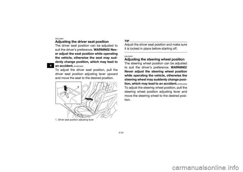
EBU34993Adjusting the driver seat positionThe driver seat position can be adjusted to
suit the driver’s preference. WARNING! Nev-
er adjust the seat position while operating
the vehicle, otherwise the seat may sud-
denly change position, which may lead to
an accident.
[EWB03990]
To adjust the driver seat position, pull the
driver seat position adjusting lever upward
and move the seat to the desired position.
TIPAdjust the driver seat position and make sure
it is locked in place before starting off. EBU35002Adjusting the steering wheel positionThe steering wheel position can be adjusted
to suit the driver’s preference. WARNING!
Never adjust the steering wheel position
while operating the vehicle, otherwise the
steering wheel may suddenly change posi-
tion, which may lead to an accident.
[EWB04000]
To adjust the steering wheel position, pull the
steering wheel position adjusting lever and
move the steering wheel to the desired posi-
tion.
1. Driver seat position adjusting lever
1
U2HC7ME0.book Page 24 Tuesday, April 19, 2016 10:33 AM
Page 64 of 208
4-26
4
When storing any documents in the glove
compartment, be sure to wrap them in a plas-
tic bag so that they will not get wet. When
washing the vehicle, be careful not to let any
water enter the glove compartment.NOTICEECB02071To protect from damage, do not put metal
items, like tools, or sharply edged items di-
rectly in the glove compartment. If they
must be stored, wrap them in appropriate
cushioning material.
EBU35010Storage compartmentsThere are storage compartments located in
the center console, under the passenger seat,
and behind the driver seat.
To access the storage compartment under
the passenger seat, remove the seat cushion
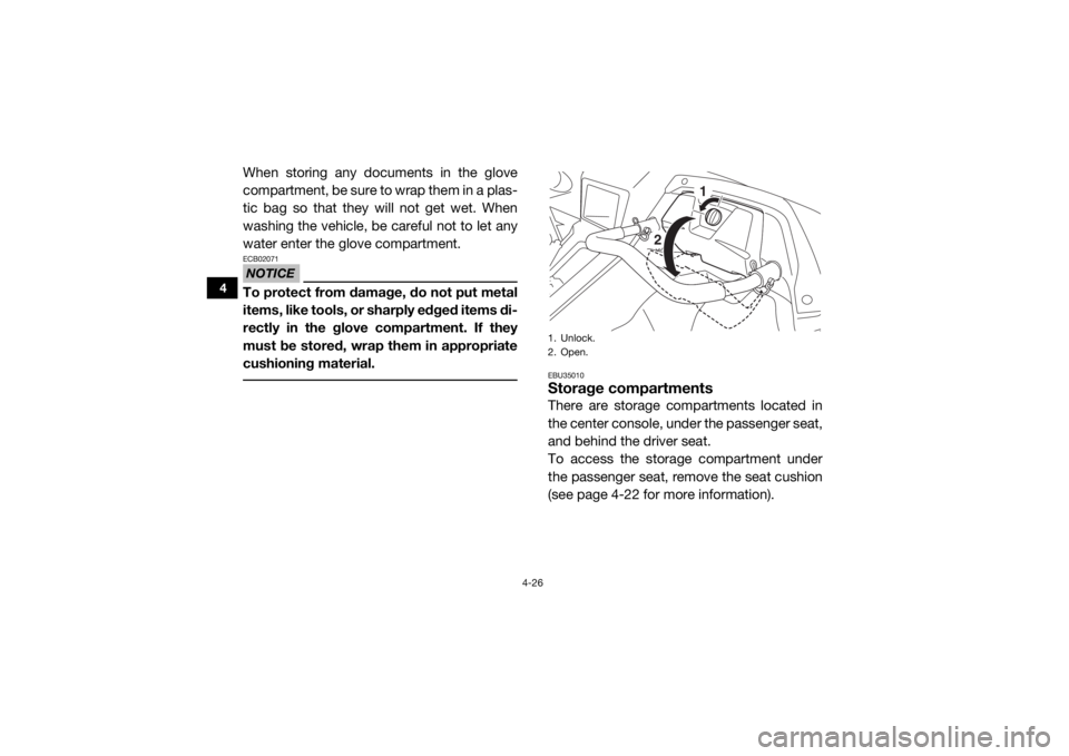
(see page 4-22 for more information).1. Unlock.
2. Open.
1
2
U2HC7ME0.book Page 26 Tuesday, April 19, 2016 10:33 AM
Page 69 of 208
4-31
4
Always adjust the shock absorber as-
semblies on the left and right side to the
same setting. Uneven adjustment can
cause poor handling and loss of stability,
which could lead to an accident. NOTICEECB00091Never turn an adjusting mechanism be-
yond the minimum and maximum settings. TIPAlthough the total number of clicks or turns of
a damping force adjusting mechanism may
not exactly match the following specifications
due to small differences in production, the ac-
tual number of clicks or turns always repre-
sents the entire adjusting range. To obtain a
precise adjustment, it would be advisable to
check the number of clicks or turns of each
damping force adjusting mechanism and to
modify the specifications as necessary.
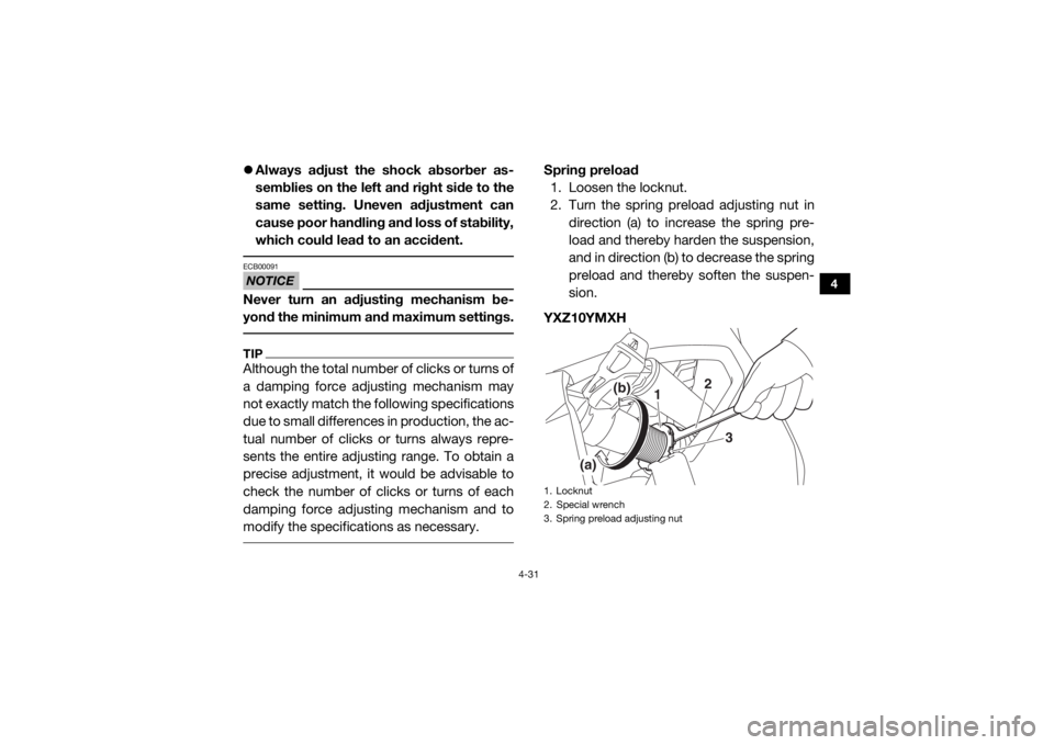
Spring preload
1. Loosen the locknut.
2. Turn the spring preload adjusting nut in
direction (a) to increase the spring pre-
load and thereby harden the suspension,
and in direction (b) to decrease the spring
preload and thereby soften the suspen-
sion.
YXZ10YMXH1. Locknut
2. Special wrench
3. Spring preload adjusting nut
2
1
3
(a)
(b)
U2HC7ME0.book Page 31 Tuesday, April 19, 2016 10:33 AM
Page 70 of 208
4-32
4
YXZ10YMSHTIPA special wrench can be obtained at a
Yamaha dealer to make this adjustment.
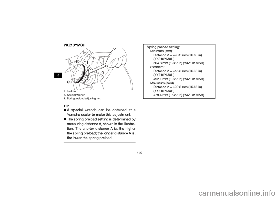
The spring preload setting is determined by
measuring distance A, shown in the illustra-
tion. The shorter distance A is, the higher
the spring preload; the longer distance A is,
the lower the spring preload. 1. Locknut
2. Special wrench
3. Spring preload adjusting nut
2
1
3
(a)
(b)
Spring preload setting:
Minimum (soft):Distance A = 428.2 mm (16.86 in)
(YXZ10YMXH)
504.8 mm (19.87 in) (YXZ10YMSH)
Standard: Distance A = 415.5 mm (16.36 in)
(YXZ10YMXH)
492.1 mm (19.37 in) (YXZ10YMSH)
Maximum (hard): Distance A = 402.8 mm (15.86 in)
(YXZ10YMXH)
479.4 mm (18.87 in) (YXZ10YMSH)
U2HC7ME0.book Page 32 Tuesday, April 19, 2016 10:33 AM
Page 71 of 208
![YAMAHA YXZ1000R SS 2017 User Guide 4-33
4
YXZ10YMXH
YXZ10YMSH3. Tighten the locknut to the specified
torque. NOTICE: Always tighten the
locknut against the adjusting nut, and
then tighten it to the specified torque.
[ECB00082]
Reboun YAMAHA YXZ1000R SS 2017 User Guide 4-33
4
YXZ10YMXH
YXZ10YMSH3. Tighten the locknut to the specified
torque. NOTICE: Always tighten the
locknut against the adjusting nut, and
then tighten it to the specified torque.
[ECB00082]
Reboun](/img/51/53899/w960_53899-70.png)
4-33
4
YXZ10YMXH
YXZ10YMSH3. Tighten the locknut to the specified
torque. NOTICE: Always tighten the
locknut against the adjusting nut, and
then tighten it to the specified torque.
[ECB00082]
Rebound damping force (YXZ10YMXH)
Turn the rebound damping force adjusting
screw in direction (a) to increase the rebound
damping force and thereby harden the damp-
ing, and in direction (b) to decrease the re-
bound damping force and thereby soften the
damping.
1. Distance A
1. Distance A
11
Tightening torque: Locknut:41 N·m (4.1 kgf·m, 30 lb·ft)
U2HC7ME0.book Page 33 Tuesday, April 19, 2016 10:33 AM
Page 77 of 208
4-39
4
Always adjust the shock absorber as-
semblies on the left and right side to the
same setting. Uneven adjustment can
cause poor handling and loss of stability,
which could lead to an accident. NOTICEECB00091Never turn an adjusting mechanism be-
yond the minimum and maximum settings. TIPAlthough the total number of clicks or turns of
a damping force adjusting mechanism may
not exactly match the following specifications
due to small differences in production, the ac-
tual number of clicks or turns always repre-
sents the entire adjusting range. To obtain a
precise adjustment, it would be advisable to
check the number of clicks or turns of each
damping force adjusting mechanism and to
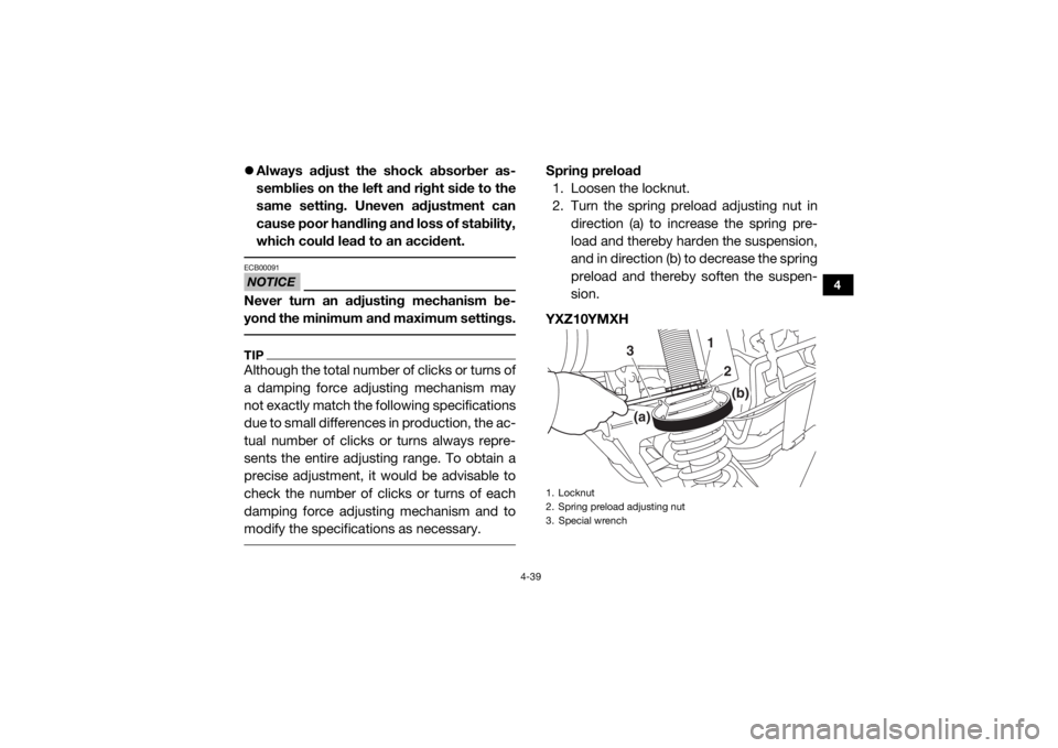
modify the specifications as necessary.
Spring preload
1. Loosen the locknut.
2. Turn the spring preload adjusting nut in
direction (a) to increase the spring pre-
load and thereby harden the suspension,
and in direction (b) to decrease the spring
preload and thereby soften the suspen-
sion.
YXZ10YMXH1. Locknut
2. Spring preload adjusting nut
3. Special wrench
1
3
2
(a)
(b)
U2HC7ME0.book Page 39 Tuesday, April 19, 2016 10:33 AM