fuse YAMAHA YXZ1000R SS 2017 Owners Manual
[x] Cancel search | Manufacturer: YAMAHA, Model Year: 2017, Model line: YXZ1000R SS, Model: YAMAHA YXZ1000R SS 2017Pages: 208, PDF Size: 4.79 MB
Page 8 of 208

Differential gear oil ............................. 8-31
Coolant ............................................... 8-33
Axle boots .......................................... 8-35
Checking the spark plugs .................. 8-35
Air filter maintenance.......................... 8-37
Cleaning the air filter case check hoses ................................................ 8-41
Cleaning the spark arrester ................ 8-42
Valve clearance .................................. 8-44
Brakes ................................................ 8-44
Checking the front and rear brake
pads.................................................. 8-44
Checking the parking brake pads ...... 8-45
Checking the brake and clutch fluid levels................................................. 8-45
Brake and clutch fluid replacement ... 8-47
Checking the clutch pedal ................. 8-47
Checking the brake pedal .................. 8-48
Checking the accelerator pedal ......... 8-49
Parking brake lever free play adjustment........................................ 8-49
Brake light switch adjustment ............ 8-50
Cable inspection and lubrication........ 8-51 Pedal lubrication .................................8-51
Checking the stabilizer bushes...........8-52
Upper and lower arm pivot
lubrication (left and right) ..................8-52
Rear knuckle upper and lower pivot
lubrication (left and right) ..................8-53
Drive shaft universal joint lubrication .........................................8-53
Steering shaft lubrication....................8-54
Wheel removal ....................................8-54
Checking and tightening the bead lock (YXZ10YMSH) ...........................8-55
Tire replacement .................................8-55
Wheel installation................................8-56
Battery ................................................8-57
Jump-starting .....................................8-60
Fuse replacement ...............................8-61
Headlights...........................................8-63
Headlight beam adjustment ...............8-64
Tail/brake light ....................................8-64
Troubleshooting ..................................8-64
Troubleshooting charts .......................8-66
U2HC7ME0.book Page 3 Tuesday, April 19, 2016 10:33 AM
Page 37 of 208
3-2
3
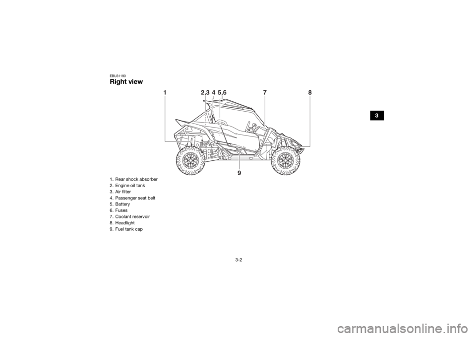
EBU31190Right view
12,3 78
4
5,6
9
1. Rear shock absorber
2. Engine oil tank
3. Air filter
4. Passenger seat belt
5. Battery
6. Fuses
7. Coolant reservoir
8. Headlight
9. Fuel tank capU2HC7ME0.book Page 2 Tuesday, April 19, 2016 10:33 AM
Page 84 of 208
4-46
4
WARNING
EWB03500These shock absorber assemblies contain
highly pressurized nitrogen gas. Read and
understand the following information be-
fore handling the shock absorber assem-
blies.
Do not tamper with or attempt to open
the cylinder assemblies.
Do not subject the shock absorber as-
sembly to an open flame or other high
heat source. This may cause the unit to
explode due to excessive gas pressure.
Do not deform or damage the cylinders
in any way. Cylinder damage will result in
poor damping performance.
Do not dispose of a damaged or worn
out shock absorber assembly yourself.
Take the shock absorber assembly to a
Yamaha dealer for any service.
EBU35052Auxiliary DC jackThe auxiliary DC jack is located at the left side
of the glove compartment. The auxiliary DC
jack can be used for suitable work lights, ra-
dios, etc. The auxiliary DC jack should only be
used when the engine is running and the
lights are turned off.NOTICEECB02250 Do not use accessories requiring more
than the stated maximum capacity. Do-
ing so may overload the circuit and cau-
se the fuse to blow.
If accessories are used without the en-
gine running, the battery may discharge.
Do not use an automotive cigarette light-
er or other accessories with a plug that
gets hot, because the jack can be dam-
aged. 1. Set the light switch to “ ” (off).
2. Turn the accessory off.
3. Start the engine. (See page 6-2.)
U2HC7ME0.book Page 46 Tuesday, April 19, 2016 10:33 AM
Page 187 of 208
8-61
8
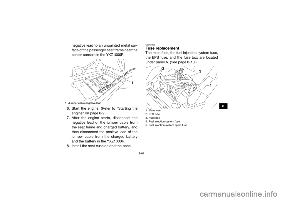
negative lead to an unpainted metal sur-
face of the passenger seat frame near the
center console in the YXZ1000R.
6. Start the engine. (Refer to “Starting the engine” on page 6-2.)
7. After the engine starts, disconnect the
negative lead of the jumper cable from
the seat frame and charged battery, and
then disconnect the positive lead of the
jumper cable from the charged battery
and the battery in the YXZ1000R.
8. Install the seat cushion and the panel.
EBU35252Fuse replacementThe main fuse, the fuel injection system fuse,
the EPS fuse, and the fuse box are located
under panel A. (See page 8-10.)
1. Jumper cable negative lead
1
1. Main fuse
2. EPS fuse
3. Fuse box
4. Fuel injection system fuse
5. Fuel injection system spare fuse
1 2
3
4
5
U2HC7ME0.book Page 61 Tuesday, April 19, 2016 10:33 AM
Page 188 of 208
8-62
8
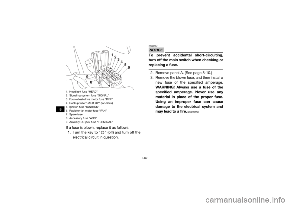
If a fuse is blown, replace it as follows.1. Turn the key to “ ” (off) and turn off the electrical circuit in question.
NOTICEECB00641To prevent accidental short-circuiting,
turn off the main switch when checking or
replacing a fuse. 2. Remove panel A. (See page 8-10.)
3. Remove the blown fuse, and then install anew fuse of the specified amperage.
WARNING! Always use a fuse of the
specified amperage. Never use any
material in place of the proper fuse.
Using an improper fuse can cause
damage to the electrical system and
may lead to a fire.
[EWB03440]
1. Headlight fuse “HEAD”
2. Signaling system fuse “SIGNAL”
3. Four-wheel-drive motor fuse “DIFF”
4. Backup fuse “BACK UP” (for clock)
5. Ignition fuse “IGNITION”
6. Radiator fan motor fuse “FAN”
7. Spare fuse
8. Accessory fuse “ACC”
9. Auxiliary DC jack fuse “TERMINAL”
1234
5
6
7
8
9
U2HC7ME0.book Page 62 Tuesday, April 19, 2016 10:33 AM
Page 189 of 208
8-63
8
4. Turn the key to “ ” (on) and turn on theelectrical circuit in question to check if
the device operates. If the fuse blows
again immediately, have a Yamaha dealer
check the electrical system.
5. Install the panel.EBU35261HeadlightsThis model is equipped with LED headlights.
There are no user replaceable bulbs. If one or
more headlights do not come on, check for a
loose connection, check the headlight fuse,
and then have a Yamaha dealer check the ve-
hicle.TIP When the headlights are set to low beam,
only the top half of each lamp will illuminate.
When the headlights are set to high beam,
both halves of each lamp will illuminate.
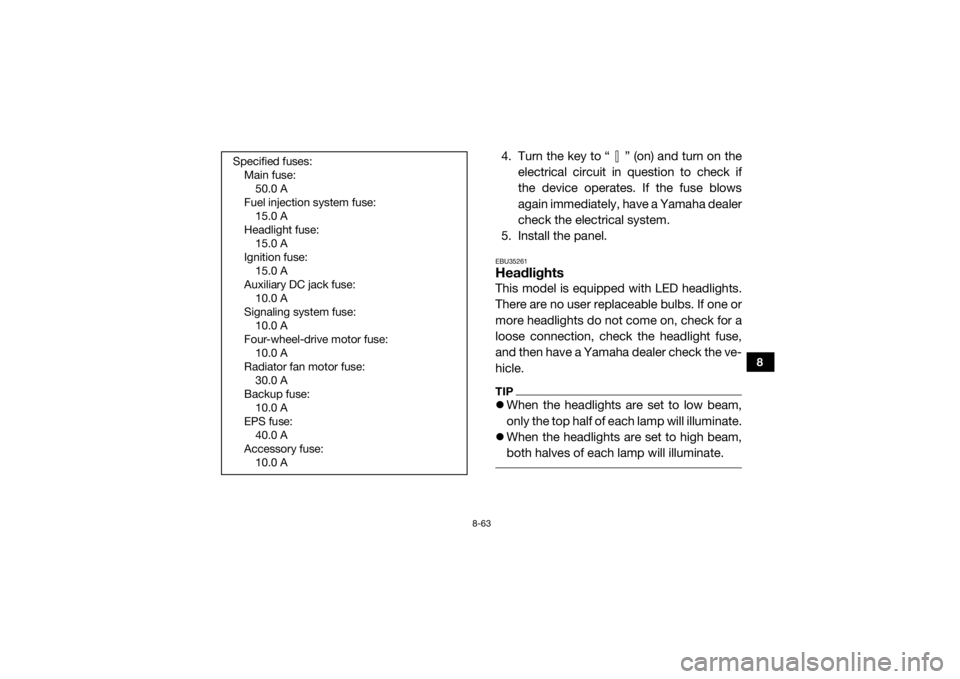
Specified fuses:
Main fuse:50.0 A
Fuel injection system fuse: 15.0 A
Headlight fuse: 15.0 A
Ignition fuse: 15.0 A
Auxiliary DC jack fuse: 10.0 A
Signaling system fuse: 10.0 A
Four-wheel-drive motor fuse: 10.0 A
Radiator fan motor fuse: 30.0 A
Backup fuse: 10.0 A
EPS fuse: 40.0 A
Accessory fuse: 10.0 A
U2HC7ME0.book Page 63 Tuesday, April 19, 2016 10:33 AM
Page 190 of 208
8-64
8
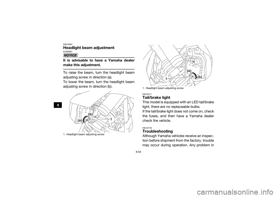
EBU32681Headlight beam adjustmentNOTICEECB00691It is advisable to have a Yamaha dealer
make this adjustment. To raise the beam, turn the headlight beam
adjusting screw in direction (a).
To lower the beam, turn the headlight beam
adjusting screw in direction (b).
EBU35271Tail/brake lightThis model is equipped with an LED tail/brake
light, there are no replaceable bulbs.
If the tail/brake light does not come on, check
the fuses, and then have a Yamaha dealer
check the vehicle.EBU32700TroubleshootingAlthough Yamaha vehicles receive an inspec-
tion before shipment from the factory, trouble
may occur during operation. Any problem in
1. Headlight beam adjusting screw
(a)
(b)
1
1. Headlight beam adjusting screw
(b)
(a)
1
U2HC7ME0.book Page 64 Tuesday, April 19, 2016 10:33 AM
Page 201 of 208

10-5
10
Electrical system:Ignition system:TCI
Charging system:
AC magnetoBattery:Model:U1-H11L
Voltage, capacity:
12 V, 28.0 AhBulb voltage, wattage × quantity:Headlight:
LED
Tail/brake light:
LED
Neutral indicator light: LED
High beam indicator light: LED
Reverse indicator light:
LED
Coolant temperature warning light: LED
Engine trouble warning light: LED
Parking brake indicator light:
LED
Differential gear lock indicator light: LED
EPS warning light: LED Helmet/Seat belt indicator light:
14 V, 0.85 W × 2
Shift timing indicator light: LED
Fuses:Main fuse:50.0 A
Fuel injection system fuse: 15.0 A
EPS fuse:
40.0 A
Headlight fuse: 15.0 A
Signaling system fuse: 10.0 A
Ignition fuse:
15.0 A
Auxiliary DC jack fuse: 10.0 A
Accessory fuse: 10.0 A
Backup fuse:
10.0 A
Four-wheel-drive motor fuse: 10.0 A
Radiator fan motor fuse: 30.0 A
U2HC7ME0.book Page 5 Tuesday, April 19, 2016 10:33 AM
Page 205 of 208

12-1
12
INDEX
AAccelerator pedal ......................................................... 4-18
Accelerator pedal, checking ........................................ 8-49
Accelerator pedal, Pre-operation check ........................ 5-7
Air filter ......................................................................... 8-37
Air filter case hoses, cleaning ...................................... 8-41
Auxiliary DC jack .......................................................... 4-46
Axle boots .................................................................... 8-35BBasic guide for safe use ................................................ 7-1
Battery, Periodic maintenance .................................... 8-57
Bead lock, checking and tightening (YXZ10YMSH) .... 8-55
Brake and clutch fluid levels, checking ....................... 8-45
Brake fluid, replacing ................................................... 8-47
Brake light switch, adjusting ........................................ 8-50
Brake pedal .................................................................. 4-19
Brake pedal, checking ................................................. 8-48
Brakes, Periodic maintenance ..................................... 8-44
Brakes, Pre-operation check ......................................... 5-3CCable, inspecting and lubrication ................................ 8-51
Cargo bed .................................................................... 4-29
Cleaning ......................................................................... 9-1
Clutch pedal ................................................................. 4-19
Clutch pedal, checking ................................................ 8-47
Clutch, Pre-operation check .......................................... 5-3
Control cables, Pre-operation check ............................. 5-8
Coolant, Periodic maintenance ................................... 8-33
Coolant, Pre-operation check ........................................ 5-6Coolant temperature warning light ................................ 4-4
Cup holders ................................................................. 4-28
DDifferential gear lock indicator light ............................... 4-3
Differential gear oil, Periodic maintenance .................. 8-31
Differential gear, Pre-operation check ........................... 5-7
Doors ........................................................................... 4-22
Drive mode, selecting .................................................... 6-7
Driver seat position ...................................................... 4-24
Drive shaft universal joint, lubrication .......................... 8-53
Drivetrain icon ................................................................ 4-3EEngine break-in .............................................................. 6-1
Engine oil and oil filter, Periodic maintenance ............. 8-15
Engine oil, Pre-operation check .................................... 5-5
Engine trouble warning light .......................................... 4-5
EPS warning light .......................................................... 4-5FFinal gear oil, Periodic maintenance ............................ 8-29
Final gear, Pre-operation check .................................... 5-6
Fittings and fasteners, Pre-operation check ................. 5-8
Flag pole bracket ......................................................... 4-30
Front and rear brake pads, checking .......................... 8-44
Fuel, Pre-operation check ............................................. 5-4
Fuel tank cap ............................................................... 4-21
Fuse, replacing ............................................................ 8-61GGlove compartment ..................................................... 4-25HHeadlight beam, adjusting ........................................... 8-64
Headlights .................................................................... 8-63
U2HC7ME0.book Page 1 Tuesday, April 19, 2016 10:33 AM