light YAMAHA YXZ1000R SS 2017 Owners Manual
[x] Cancel search | Manufacturer: YAMAHA, Model Year: 2017, Model line: YXZ1000R SS, Model: YAMAHA YXZ1000R SS 2017Pages: 208, PDF Size: 4.79 MB
Page 6 of 208

EBU31120
CONTENTS
LOCATION OF THE WARNING AND
SPECIFICATION LABELS ....................... 1-1
SAFETY INFORMATION ......................... 2-1
DESCRIPTION......................................... 3-1Left view ............................................... 3-1
Right view ............................................. 3-2
Controls and instruments ..................... 3-3
INSTRUMENT AND CONTROL
FUNCTIONS............................................ 4-1 Main switch .......................................... 4-1
Indicator lights and warning lights ....... 4-2
Multi-function meter unit ...................... 4-7
Light switch ........................................ 4-16
On-Command drive knob “2WD/4WD/DIFF LOCK” .................. 4-17
Reverse gear lock lever “REV.” .......... 4-18
Accelerator pedal ............................... 4-18
Clutch pedal ....................................... 4-19 Brake pedal ........................................ 4-19
Parking brake lever ............................ 4-20
Shift lever ........................................... 4-21
Fuel tank cap...................................... 4-21
Doors .................................................. 4-22
Seats .................................................. 4-22
Adjusting the driver seat position....... 4-24
Adjusting the steering wheel
position ............................................. 4-24
Seat belts ........................................... 4-25
Glove compartment ........................... 4-25
Storage compartments ...................... 4-26
Cup holders ........................................ 4-28
Cargo bed .......................................... 4-29
Flag pole bracket ............................... 4-30
Adjusting the front shock absorber assemblies ....................................... 4-30
Adjusting the rear shock absorber assemblies ....................................... 4-38
Auxiliary DC jack ................................ 4-46U2HC7ME0.book Page 1 Tuesday, April 19, 2016 10:33 AM
Page 7 of 208

FOR YOUR SAFETY –
PRE-OPERATION CHECKS .................... 5-1Front and rear brakes ........................... 5-3
Clutch ................................................... 5-3
Fuel ....................................................... 5-4
Engine oil .............................................. 5-5
Transmission ........................................ 5-6
Coolant ................................................. 5-6
Final gear .............................................. 5-6
Differential gear .................................... 5-7
Accelerator pedal ................................. 5-7
Seat belts ............................................. 5-7
Passenger handhold ............................ 5-7
Steering ................................................ 5-7
Shift lever.............................................. 5-8
Fittings and fasteners ........................... 5-8
Instruments, lights and switches .......... 5-8
Control cables ...................................... 5-8
Tires ...................................................... 5-8
OPERATION ............................................ 6-1 Engine break-in .................................... 6-1
Starting the engine ............................... 6-2 Shift lever operation and reverse
driving .................................................6-3
Selecting the drive mode ......................6-7
Parking ..................................................6-9
Loading .................................................6-9
BASIC GUIDE FOR SAFE USE ...............7-1 KNOW YOUR VEHICLE ........................7-1
LEARNING TO OPERATE YOUR VEHICLE ...........................................7-12
PERIODIC MAINTENANCE AND
ADJUSTMENT .........................................8-1 Owner’s manual and tool kit .................8-2
Periodic maintenance chart for the emission control system .....................8-4
General maintenance and lubrication chart ....................................................8-6
Hood ...................................................8-10
Panels .................................................8-10
Engine oil and oil filter.........................8-15
Transmission oil ..................................8-26
Final gear oil .......................................8-29U2HC7ME0.book Page 2 Tuesday, April 19, 2016 10:33 AM
Page 8 of 208

Differential gear oil ............................. 8-31
Coolant ............................................... 8-33
Axle boots .......................................... 8-35
Checking the spark plugs .................. 8-35
Air filter maintenance.......................... 8-37
Cleaning the air filter case check hoses ................................................ 8-41
Cleaning the spark arrester ................ 8-42
Valve clearance .................................. 8-44
Brakes ................................................ 8-44
Checking the front and rear brake
pads.................................................. 8-44
Checking the parking brake pads ...... 8-45
Checking the brake and clutch fluid levels................................................. 8-45
Brake and clutch fluid replacement ... 8-47
Checking the clutch pedal ................. 8-47
Checking the brake pedal .................. 8-48
Checking the accelerator pedal ......... 8-49
Parking brake lever free play adjustment........................................ 8-49
Brake light switch adjustment ............ 8-50
Cable inspection and lubrication........ 8-51 Pedal lubrication .................................8-51
Checking the stabilizer bushes...........8-52
Upper and lower arm pivot
lubrication (left and right) ..................8-52
Rear knuckle upper and lower pivot
lubrication (left and right) ..................8-53
Drive shaft universal joint lubrication .........................................8-53
Steering shaft lubrication....................8-54
Wheel removal ....................................8-54
Checking and tightening the bead lock (YXZ10YMSH) ...........................8-55
Tire replacement .................................8-55
Wheel installation................................8-56
Battery ................................................8-57
Jump-starting .....................................8-60
Fuse replacement ...............................8-61
Headlights...........................................8-63
Headlight beam adjustment ...............8-64
Tail/brake light ....................................8-64
Troubleshooting ..................................8-64
Troubleshooting charts .......................8-66
U2HC7ME0.book Page 3 Tuesday, April 19, 2016 10:33 AM
Page 37 of 208
3-2
3
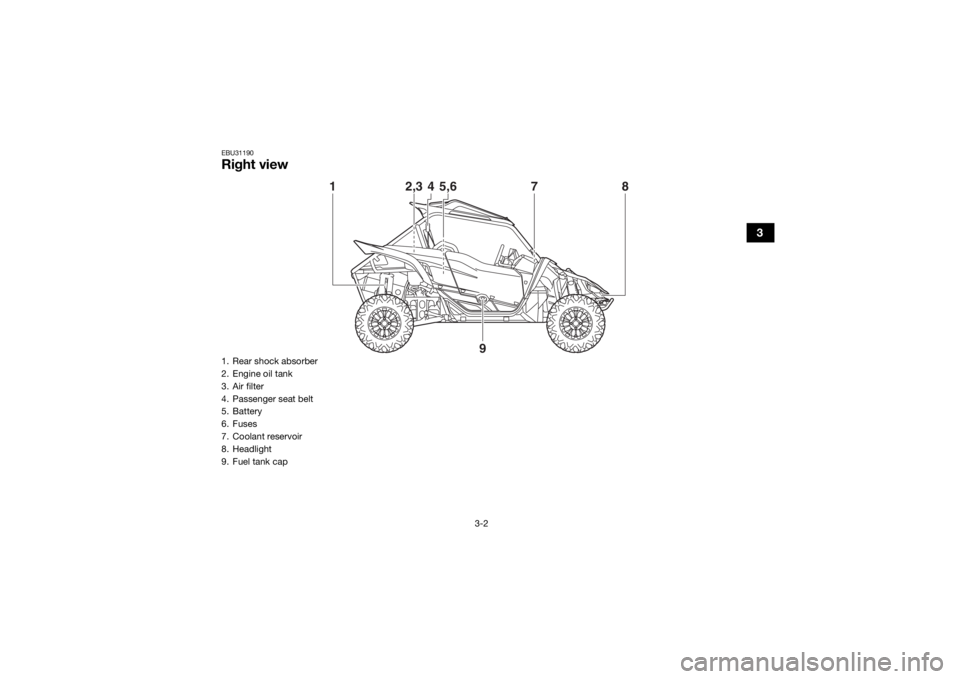
EBU31190Right view
12,3 78
4
5,6
9
1. Rear shock absorber
2. Engine oil tank
3. Air filter
4. Passenger seat belt
5. Battery
6. Fuses
7. Coolant reservoir
8. Headlight
9. Fuel tank capU2HC7ME0.book Page 2 Tuesday, April 19, 2016 10:33 AM
Page 38 of 208
3-3
3
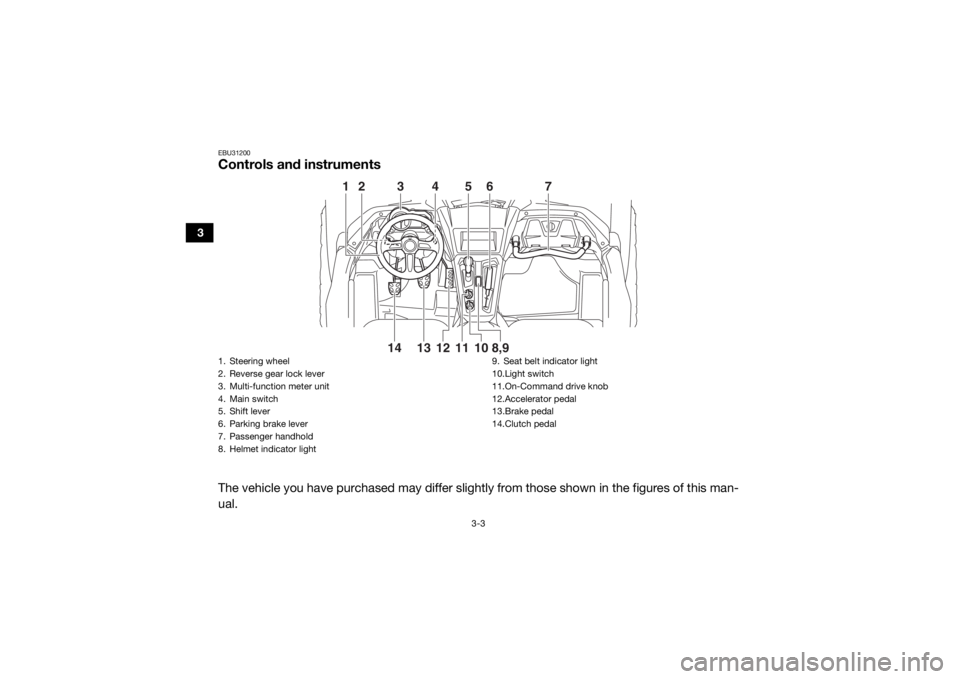
EBU31200Controls and instrumentsThe vehicle you have purchased may differ slightly from those shown in the figures of this man-
ual.
345
6
7
1
212
10
8,9
13 11
14
1. Steering wheel
2. Reverse gear lock lever
3. Multi-function meter unit
4. Main switch
5. Shift lever
6. Parking brake lever
7. Passenger handhold
8. Helmet indicator light 9. Seat belt indicator light
10.Light switch
11.On-Command drive knob
12.Accelerator pedal
13.Brake pedal
14.Clutch pedalU2HC7ME0.book Page 3 Tuesday, April 19, 2016 10:33 AM
Page 39 of 208
4-1
4
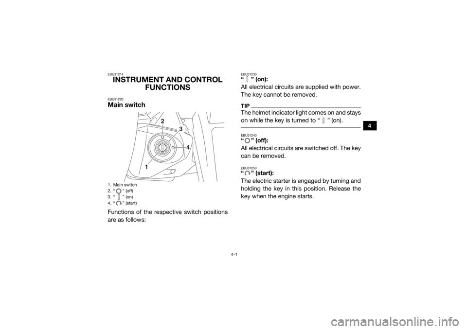
EBU31214INSTRUMENT AND CONTROL FUNCTIONSEBU31220Main switchFunctions of the respective switch positions
are as follows:
EBU31230“” (on):
All electrical circuits are supplied with power.
The key cannot be removed.TIPThe helmet indicator light comes on and stays
on while the key is turned to “ ” (on). EBU31240“ ” (off):
All electrical circuits are switched off. The key
can be removed.EBU31250“” (start):
The electric starter is engaged by turning and
holding the key in this position. Release the
key when the engine starts.
1. Main switch
2. “ ” (off)
3. “ ” (on)
4. “ ” (start)
1
2
3
4
U2HC7ME0.book Page 1 Tuesday, April 19, 2016 10:33 AM
Page 40 of 208
4-2
4
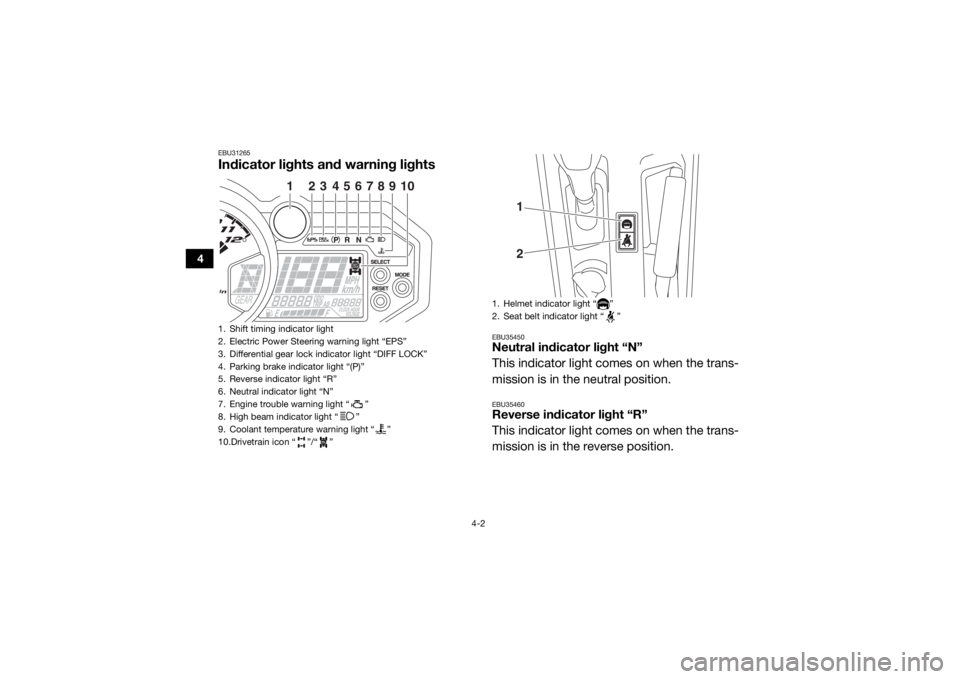
EBU31265Indicator lights and warning lights
EBU35450Neutral indicator light “N”
This indicator light comes on when the trans-
mission is in the neutral position.EBU35460Reverse indicator light “R”
This indicator light comes on when the trans-
mission is in the reverse position.
1. Shift timing indicator light
2. Electric Power Steering warning light “EPS”
3. Differential gear lock indicator light “DIFF LOCK”
4. Parking brake indicator light “(P)”
5. Reverse indicator light “R”
6. Neutral indicator light “N”
7. Engine trouble warning light “ ”
8. High beam indicator light “ ”
9. Coolant temperature warning light “ ”
10.Drivetrain icon “ ”/“ ”
1
2
3
45
6
78
10
9
1. Helmet indicator light “ ”
2. Seat belt indicator light “ ”
12
U2HC7ME0.book Page 2 Tuesday, April 19, 2016 10:33 AM
Page 41 of 208
4-3
4
EBU34910Parking brake indicator light “(P)”
This indicator light comes on when the park-
ing brake is applied.EBU36450High beam indicator light “ ”
This indicator light comes on when the high
beam of the headlight is switched on.EBU35850Differential gear lock indicator light “DIFF
LOCK”
This indicator light comes on when the front
differential gear is locked.EBU34921Drivetrain icon “ / ”
The drivetrain icon indicates what type of
drive mode is currently selected. When 2WD
is selected, the icon will turn off. When 4WD
is selected, “ ” is displayed. And when 4WD
with differential lock is selected “ ” is dis-
played.
TIP See pages 4-17 and 6-7 for more informa-
tion on selecting the drive mode.
Due to the synchronizing mechanism in the
differential gear case, the drivetrain icon
may not come on until the vehicle starts
moving.
When the On-Command drive knob is set
to “DIFF LOCK” or “4WD”, the drivetrain
icon and the differential gear lock indicator
light will flash until the differential gear is
completely locked or unlocked. If the icon
and the indicator light continue to flash, the
differential is not completely locked or un-
locked. In this case, start moving slowly
and/or turn the steering wheel back and
forth to help the differential to lock or un-
lock.
U2HC7ME0.book Page 3 Tuesday, April 19, 2016 10:33 AM
Page 42 of 208
4-4
4
EBU34931Shift timing indicator light
This indicator light can be set to come on and
go off at the desired engine speeds and is
u s ed t o i n fo rm t h e dr iv er wh e n it i s ti m e t o u p -
shift.
The electrical circuit of the indicator light can
be checked by turning the key to “ ” (on). If
the indicator light does not come on initially
when the key is turned to “ ” (on), or if the
indicator light remains on, have a Yamaha
dealer check the electrical circuit.TIPSee page 4-13 for a detailed explanation of
this indicator light and how to set it. EBU35282Coolant temperature warning light “ ”
This warning light comes on when the coolant
temperature, and therefore the engine, is out-
side its normal operating temperature range.The warning light comes on in blue to inform
the driver that the vehicle should be warmed
up. After the engine is started, warm it up until
the warning light goes off.
The vehicle can be operated normally when
the warning light is off.
The warning light comes on in red when the
engine is overheating. If the red light comes
on, stop the vehicle as soon as it is safe to do
so and allow the engine to idle for about 10
minutes. If the warning light does not go off,
stop the engine and allow it to cool. (See page
8-67.)
TIPThe coolant temperature warning light can be
checked by turning the key to “ ” (on). The
warning light should come on in purple briefly
(which confirms that both the blue and red in-
dicators are okay) and then go off. If the warn-
ing light does not come on at all, comes on in
red or blue, or if the warning light remains on,
have a Yamaha dealer check the vehicle.
U2HC7ME0.book Page 4 Tuesday, April 19, 2016 10:33 AM
Page 43 of 208
4-5
4
NOTICEECB02040The engine may overheat if the vehicle is
overloaded. If this happens, reduce the
load to specification.
After restarting, make sure that the
warning light is out. Continuous use
while this warning light is on may cause
damage to the engine. EBU31341Engine trouble warning light “ ”
This warning light comes on or flashes if a
problem is detected in the electrical circuit
monitoring the engine. When this occurs, the
display will indicate an error code (see page
4-16). Have a Yamaha dealer check the self-
diagnosis system.
The electrical circuit of the warning light can
be checked by turning the key to “ ” (on). If
the warning light does not come on initially when the key is turned to “ ” (on), or if the
warning light remains on, have a Yamaha
dealer check the vehicle.
EBU33041Electric Power Steering warning light
“EPS”
This warning light comes on when the key is
turned to “ ” (on), and then goes off once
the engine is started. If the warning light re-
mains on or comes on after the engine is
started, the EPS system may not be working
correctly. When this occurs, have a Yamaha
dealer check the EPS system.
The electrical circuit of the warning light can
be checked by turning the key to “ ” (on). If
the warning light does not come on, have a
Yamaha dealer check the electrical circuit.
U2HC7ME0.book Page 5 Tuesday, April 19, 2016 10:33 AM