clutch YAMAHA YZ125LC 2001 Betriebsanleitungen (in German)
[x] Cancel search | Manufacturer: YAMAHA, Model Year: 2001, Model line: YZ125LC, Model: YAMAHA YZ125LC 2001Pages: 558, PDF-Größe: 13.11 MB
Page 118 of 558

2-14
SPECCABLE ROUTING DIAGRAM
1Brake hose holder
2Master cylinder
3Brake hose
4Hose guide
5CDI unit band
6CDI unit
7High tension cord
8Ignition coil
9Cable guide
0Radiator breather hose
qWireharness
w“ENGINE STOP” button lead
eCDI magneto lead
rClutch cable
tClamp
yCDI unit bracket
uEngine bracket
iCDI unit damper
APass the brake hose into
the brake hose holder.BIf the brake hose contacts
the spring (rear shock
absorber), correct its twist.
CInstall the brake hose so that
its pipe portion directs as
shown and lightly touches
the projection on the master
cylinder.
DPass the reservoir hose
between the brake hose and
swingarm bracket.
EPut the CDI unit fully in
the CDI unit band.
FFasten the ground lead
together with the ignition
coil.
GPass the cluch cable into
the cable guide.
HClamp the CDI magneto lead
on the upper part of
the frame gusset at its
protecting tube.IPass the clutch cable over
the radiator hose.
JClamp the wireharness on
the top of the CDI unit with
the clamp end downward.
KCut the clamp end to be flush
with CDI unit side.
LFit the CDI unit band over
the CDI unit bracket till it
stops.
MInstall the brake hose to
the caliper with the paint on
the pipe facing the caliper
and with the pipe contacting
the caliper projection.
NPass the radiator breather
hose between the frame and
radiator hose so that it is not
kinked or wedged.
OPosition the CDI unit between
the engine brackets as
shown.
5MV-9-30-2B 6/19/00 1:14 PM Page 28
Page 120 of 558

2-15
SPECCABLE ROUTING DIAGRAM
AInstall the brake hose so that its pipe portion
directs as show and lightly touches the
projection on the master cylinder.
BPass the “ENGINE STOP” button lead in
the middle of the clutch holder.
CPass the clutch cable in front of the throttle
cable.
DClamp the “ENGINE STOP” button lead to
the handlebar to 3 clicks.
EPass the brake hose in front of the number
plate and through the cable guide.
FCross the clutch cable and throttle cable
over the number plate boss. 1Brake hose
2Master cylinder
3“ENGINE STOP” button lead
4“ENGINE STOP” button
5Throttle cable
6Clutch cable
7Clamp
8Cable guide
5MV-9-30-2B 6/19/00 1:14 PM Page 30
Page 122 of 558
3-1
MAINTENANCE INTERVALS
INSP
ADJ
EC300000
REGULAR INSPECTION AND ADJUSTMENTS
EC310051
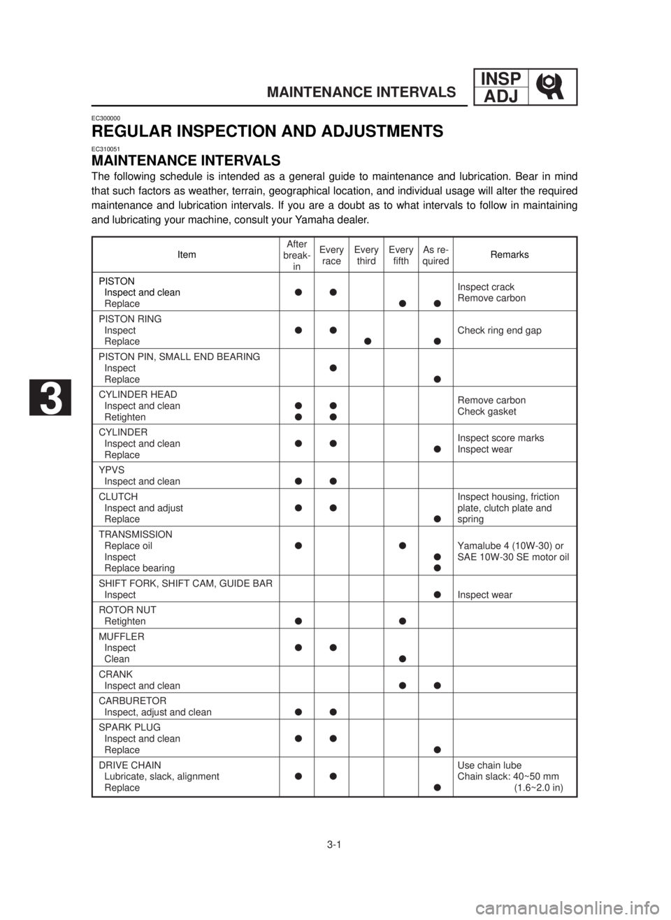
MAINTENANCE INTERVALS
The following schedule is intended as a general guide to maintenance and lubrication. Bear in mind
that such factors as weather, terrain, geographical location, and individual usage will alter the required
maintenance and lubrication intervals. If you are a doubt as to what intervals to follow in maintaining
and lubricating your machine, consult your Yamaha dealer.
Item Remarks
PISTON
Inspect and cleanllInspect crack
ReplacellRemove carbon
PISTON RING
InspectllCheck ring end gap
Replacell
PISTON PIN, SMALL END BEARING
Inspectl
Replacel
CYLINDER HEAD
Inspect and cleanllRemove carbon
RetightenllCheck gasket
CYLINDER
Inspect and cleanll
lInspect score marks
ReplaceInspect wear
YPVS
Inspect and cleanll
CLUTCHInspect housing, friction
Inspect and adjustllplate, clutch plate and
Replacelspring
TRANSMISSION
Replace oilllYamalube 4 (10W-30) or
InspectlSAE 10W-30 SE motor oil
Replace bearingl
SHIFT FORK, SHIFT CAM, GUIDE BAR
InspectlInspect wear
ROTOR NUT
Retightenll
MUFFLER
Inspectll
Cleanl
CRANK
Inspect and cleanll
CARBURETOR
Inspect, adjust and cleanll
SPARK PLUG
Inspect and cleanll
Replacel
DRIVE CHAIN Use chain lube
Lubricate, slack, alignmentllChain slack: 40~50 mm
Replacel(1.6~2.0 in)
After
break-
inEvery
raceEvery
thirdEvery
fifthAs re-
quired
3
5MV-9-30-3A 6/19/00 1:52 PM Page 2
Page 134 of 558

3-4
PRE-OPERATION INSPECTION AND MAINTENANCE
INSP
ADJ
EC320000
PRE-OPERATION INSPECTION AND MAINTENANCE
Before riding for break-in operation, practice or a race, make sure the machine is in good operating
condition.
Before using this machine, check the following points.
EC321000
GENERAL INSPECTION AND MAINTENANCE
Item Routine Page
Coolant Check that coolant is filled up to the radiator filler cap.
Check the cooling system for leakage.P3-5~9
Fuel Check that a fresh mixture of oil and gasoline is filled in
the fuel tank. Check the fuel line for leakage.P1-12
Transmission oil Check that the oil level is correct. Check the crankcase
for leakage.P3-12~14
Gear shifter and clutch Check that gears can be shifted correctly in order and
that the clutch operates smoothly.P3-9
Throttle grip/Housing Check that the throttle grip operation and free play
are correctly adjusted. Lubricate the throttle grip and P3-10~11
housing, if necessary.
Brakes Check the play of front brake and effect of front and
rear brake.P3-17~23
Chain Check chain slack and alignment. Check that the chain
is lubricated properly.P3-24~26
Wheels Check for excessive wear and tire pressure. Check for
loose spokes and have no excessive play.P3-34~35
Steering Check that the handlebar can be turned smoothly and
have no excessive play.P3-35~36
Front forks and Check that they operate smoothly and there is no oil
rear shock absorber leakage.P3-26~33
Cables (wires) Check that the clutch and throttle cables move smooth-
ly. Check that they are not caught when the handlebars —
are turned or when the front forks travel up and down.
Muffler Check that the muffler is tightly mounted and has no
cracks.P3-15~16
Sprocket Check that the driven sprocket tightening bolt is
not loose.P3-24
Lubrication Check for smooth operation. Lubricate if necessary. P3-37
Bolts and nuts Check the chassis and engine for loose bolts and nuts. P1-16
Lead connectors Check that the CDI magneto, CDI unit, and ignition coil
are connected tightly.P1-6
Settings Is the machine set suitably for the condition of the
racing course and weather or by taking into account the
P7-1~24
results of test runs before racing? Are inspection and
maintenance completely done?
5MV-9-30-3A 6/19/00 1:52 PM Page 14
Page 146 of 558
3-9
INSP
ADJ
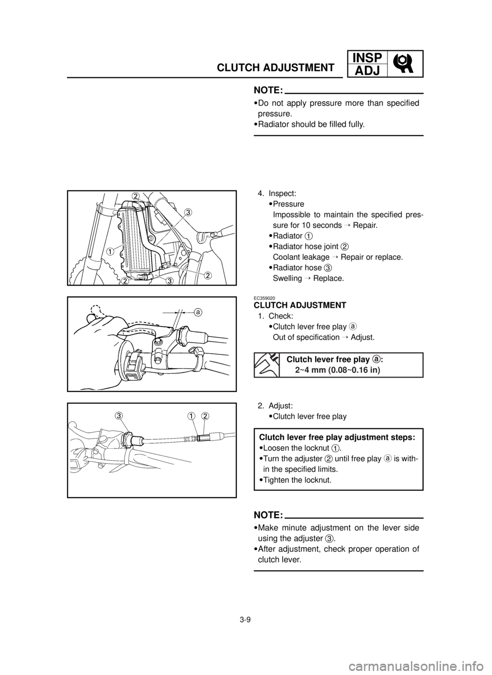
CLUTCH ADJUSTMENT
NOTE:
9Do not apply pressure more than specified
pressure.
9Radiator should be filled fully.
4. Inspect:
9Pressure
Impossible to maintain the specified pres-
sure for 10 seconds ÕRepair.
9Radiator 1
9Radiator hose joint 2
Coolant leakage ÕRepair or replace.
9Radiator hose 3
Swelling ÕReplace.
2. Adjust:
9Clutch lever free play
EC359020
CLUTCH ADJUSTMENT
1. Check:
9Clutch lever free play a
Out of specification ÕAdjust.
NOTE:
9Make minute adjustment on the lever side
using the adjuster 3.
9After adjustment, check proper operation of
clutch lever.
Clutch lever free play a a
:
2~4 mm (0.08~0.16 in)
Clutch lever free play adjustment steps:
9Loosen the locknut 1.
9Turn the adjuster 2until free play ais with-
in the specified limits.
9Tighten the locknut.
5MV-9-30-3A 6/19/00 1:52 PM Page 26
Page 202 of 558
3-37
LUBRICATION
INSP
ADJ
EC36a042
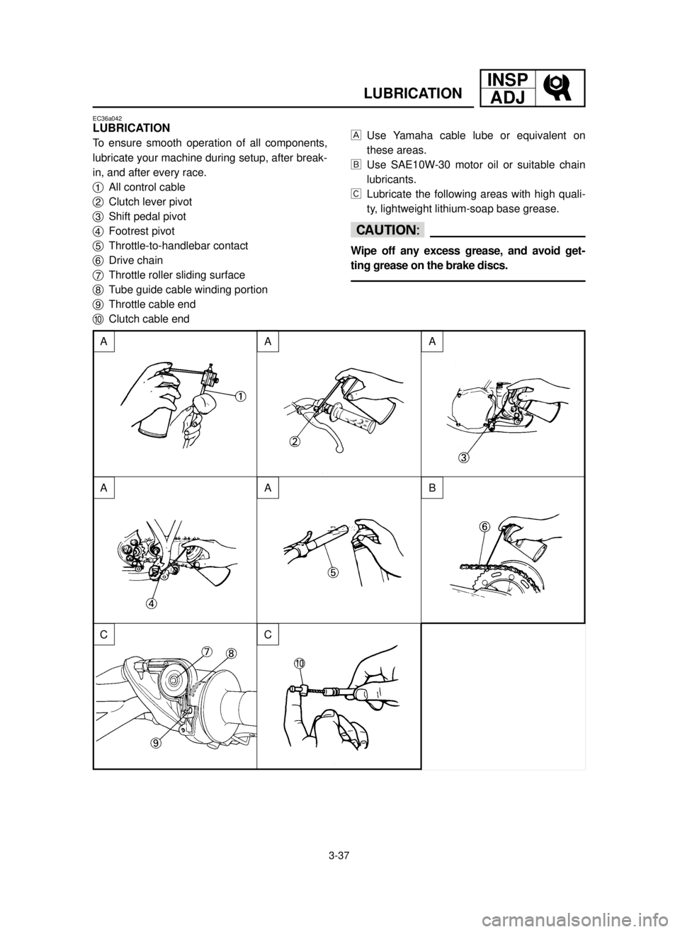
LUBRICATION
To ensure smooth operation of all components,
lubricate your machine during setup, after break-
in, and after every race.
1All control cable
2Clutch lever pivot
3Shift pedal pivot
4Footrest pivot
5Throttle-to-handlebar contact
6Drive chain
7Throttle roller sliding surface
8Tube guide cable winding portion
9Throttle cable end
0Clutch cable endUse Yamaha cable lube or equivalent on
these areas.
õUse SAE10W-30 motor oil or suitable chain
lubricants.
‚Lubricate the following areas with high quali-
ty, lightweight lithium-soap base grease.
cC
Wipe off any excess grease, and avoid get-
ting grease on the brake discs.
A
A
CC
AB
AA
5MV-9-30-3B 6/19/00 1:49 PM Page 38
Page 268 of 558
4-30
ENGCLUTCH AND PRIMARY DRIVEN GEAR
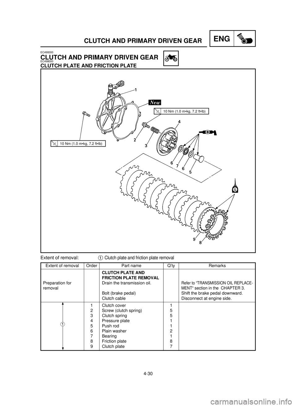
Extent of removal Order Part name Q’ty Remarks
CLUTCH PLATE AND
FRICTION PLATE REMOVAL
Preparation for Drain the transmission oil.
Refer to “TRANSMISSION OIL REPLACE-
removalMENT“ section in the CHAPTER 3.
Bolt (brake pedal) Shift the brake pedal downward.
Clutch cable Disconnect at engine side.
1 Clutch cover 1
2 Screw (clutch spring) 5
3 Clutch spring 5
4 Pressure plate 1
5 Push rod 1
6 Plain washer 2
7 Bearing 1
8 Friction plate 8
9 Clutch plate 7
Extent of removal:1Clutch plate and friction plate removal
EC490000
CLUTCH AND PRIMARY DRIVEN GEAREC498000
CLUTCH PLATE AND FRICTION PLATE
1
10 Nm (1.0 m•kg, 7.2 ft•lb)
10 Nm (1.0 m•kg, 7.2 ft•lb)
5MV-9-30-4B 6/19/00 1:44 PM Page 26
Page 270 of 558

4-31
ENGCLUTCH AND PRIMARY DRIVEN GEAR
EC498100
PRIMARY DRIVEN GEAR
Extent of removal Order Part name Q’ty Remarks
PRIMARY DRIVEN GEAR
REMOVAL
1 Nut (clutch boss) 1
Use special tool.
2 Lock washer 1
Refer to “REMOVAL POINTS”.
3 Clutch boss 1
4
Plain washer [φ34 mm (1.34 in)] 1
5 Primary driven gear 1
6 Bearing 1
7
Plain washer [φ34 mm (1.34 in)]1
8 Push lever 1
Extent of removal:1Primary driven gear removal2Push lever removal
1
2
80 Nm (8.0 m•kg, 58 ft•lb)
7 Nm (0.7 m•kg, 5.1 ft•lb)
5MV-9-30-4B 1/7/04 5:29 PM Page 28
Page 272 of 558
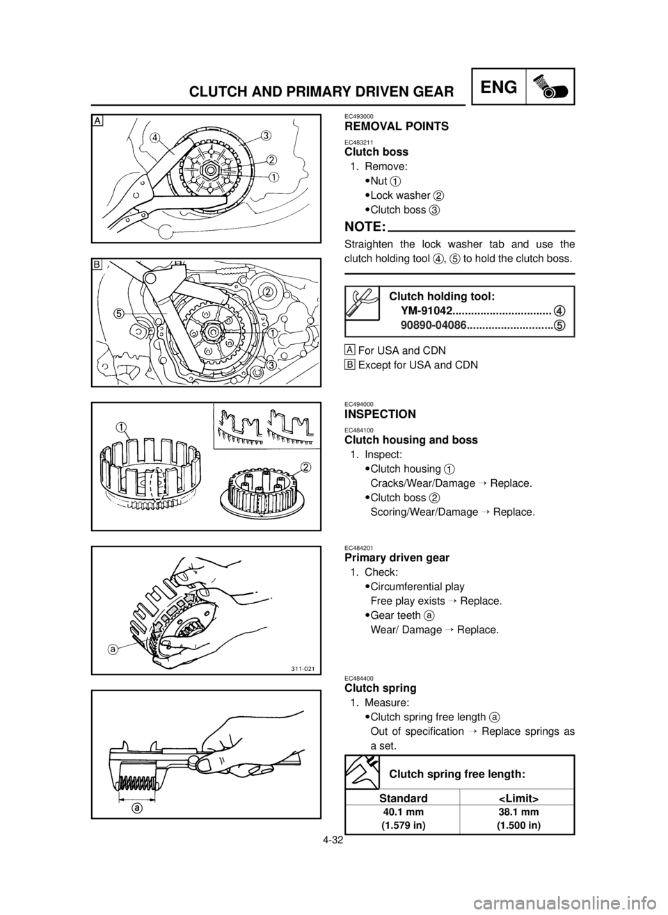
4-32
ENGCLUTCH AND PRIMARY DRIVEN GEAR
EC493000
REMOVAL POINTS
EC483211
Clutch boss
1. Remove:
9Nut 1
9Lock washer 2
9Clutch boss 3
NOTE:
Straighten the lock washer tab and use the
clutch holding tool 4, 5to hold the clutch boss.
Œ
For USA and CDN
º
Except for USA and CDN
EC494000
INSPECTION
EC484100
Clutch housing and boss
1. Inspect:
9Clutch housing 1
Cracks/Wear/Damage Õ Replace.
9Clutch boss 2
Scoring/Wear/Damage ÕReplace.
EC484201
Primary driven gear
1. Check:
9Circumferential play
Free play exists ÕReplace.
9Gear teeth a
Wear/ Damage ÕReplace.
EC484400
Clutch spring
1. Measure:
9Clutch spring free length a
Out of specification ÕReplace springs as
a set.
Clutch holding tool:
YM-91042................................
4 4
90890-04086............................5 5
Clutch spring free length:
Standard
40.1 mm 38.1 mm
(1.579 in) (1.500 in)
Œ
ºŒ
5MV-9-30-4B 6/19/00 1:44 PM Page 30
Page 274 of 558

4-33
ENGCLUTCH AND PRIMARY DRIVEN GEAR
EC484500
Friction plate
1. Measure:
9Friction plate thickness
Out of specification ÕReplace friction
plate as a set.
Measure at all four points.
EC484600
Clutch plate
1. Measure:
9Clutch plate warpage
Out of specification ÕReplace clutch plate
as a set.
Use a surface plate 1and thickness
gauge 2.
EC494100
Push lever and push rod
1. Inspect:
9Push lever 1
9Push rod 2
Wear/Damage ÕReplace.
EC494200
Clutch cover
1. Inspect:
9Push rod bearing portion a
Wear/Damage ÕReplace.
Friction plate thickness:
Standard
2.9~3.1 mm 2.8 mm
(0.114~0.122 in) (0.110 in)
Warp limit:
0.2 mm (0.008 in)
5MV-9-30-4B 6/19/00 1:44 PM Page 32