oil YAMAHA YZ125LC 2001 User Guide
[x] Cancel search | Manufacturer: YAMAHA, Model Year: 2001, Model line: YZ125LC, Model: YAMAHA YZ125LC 2001Pages: 558, PDF Size: 13.11 MB
Page 66 of 558
1-18
GEN
INFO
CLEANING AND STORAGE
EC1B2001
STORAGE
If your machine is to be stored for 60 days or
more, some preventive measures must be taken
to avoid deterioration. After cleaning the ma-
chine thoroughly, prepare it for storage as fol-
lows:
1. Drain the fuel tank, fuel lines, and the carbu-
retor float bowl.
2. Remove the spark plug, pour a tablespoon
of SAE 10W-30 motor oil in the spark plug
hole, and reinstall the plug. With the engine
stop switch pushed in, kick the engine over
several times to coat the cylinder walls with
oil.
3. Remove the drive chain, clean it thoroughly
with solvent, and lubricate it. Reinstall the
chain or store it in a plastic bag tied to the
frame.
4. Lubricate all control cables.
5. Block the frame up to raise the wheels off
the ground.
6. Tie a plastic bag over the exhaust pipe out-
let to prevent moisture from entering.
7. If the machine is to be stored in a humid or
salt-air environment, coat all exposed metal
surfaces with a film of light oil. Do not apply
oil to rubber parts or the seat cover.
NOTE:
Make any necessary repairs before the machine
is stored.
5MV-9-30-1B 6/20/0 5:12 PM Page 16
Page 68 of 558
2-1
SPECGENERAL SPECIFICATIONS
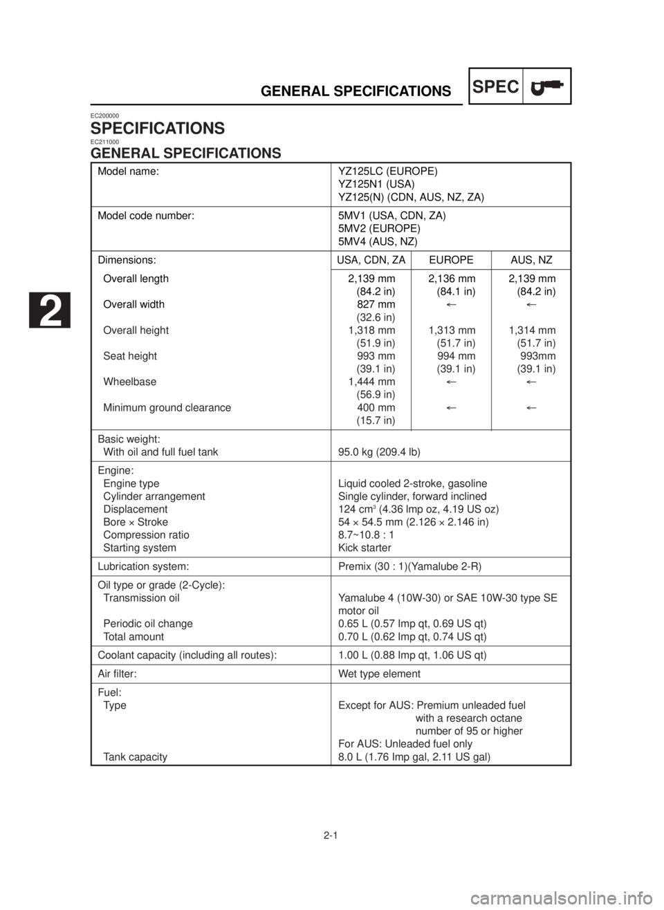
Model name: YZ125LC (EUROPE)
YZ125N1 (USA)
YZ125(N) (CDN, AUS, NZ, ZA)
Model code number: 5MV1 (USA, CDN, ZA)
5MV2 (EUROPE)
5MV4 (AUS, NZ)
Dimensions:USA, CDN, ZAEUROPE AUS, NZ
Overall length 2,139 mm 2,136 mm 2,139 mm
(84.2 in) (84.1 in) (84.2 in)
Overall width 827 mm¬¬
(32.6 in)
Overall height 1,318 mm 1,313 mm 1,314 mm
(51.9 in) (51.7 in) (51.7 in)
Seat height 993 mm 994 mm 993mm
(39.1 in) (39.1 in) (39.1 in)
Wheelbase 1,444 mm¬¬
(56.9 in)
Minimum ground clearance 400 mm¬¬
(15.7 in)
Basic weight:
With oil and full fuel tank 95.0 kg (209.4 lb)
Engine:
Engine type Liquid cooled 2-stroke, gasoline
Cylinder arrangement Single cylinder, forward inclined
Displacement 124 cm
3(4.36 lmp oz, 4.19 US oz)
Bore ´Stroke 54 ´54.5 mm (2.126 ´2.146 in)
Compression ratio 8.7~10.8 : 1
Starting system Kick starter
Lubrication system: Premix (30 : 1)(Yamalube 2-R)
Oil type or grade (2-Cycle):
Transmission oil Yamalube 4 (10W-30) or SAE 10W-30 type SE
motor oil
Periodic oil change 0.65 L (0.57 Imp qt, 0.69 US qt)
Total amount 0.70 L (0.62 Imp qt, 0.74 US qt)
Coolant capacity (including all routes): 1.00 L (0.88 Imp qt, 1.06 US qt)
Air filter: Wet type element
Fuel:
Type Except for AUS: Premium unleaded fuel
with a research octane
number of 95 or higher
For AUS: Unleaded fuel only
Tank capacity 8.0 L (1.76 Imp gal, 2.11 US gal)
EC200000
SPECIFICATIONSEC211000
GENERAL SPECIFICATIONS
2
5MV-9-30-2A 6/19/00 1:15 PM Page 2
Page 69 of 558
2-2
SPECGENERAL SPECIFICATIONS
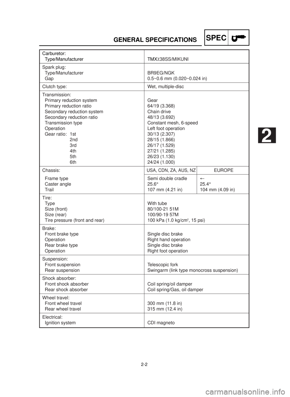
Carburetor:
Type/Manufacturer TMXø
38SS/MIKUNI
Spark plug:
Type/Manufacturer BR9EG/NGK
Gap 0.5~0.6 mm (0.020~0.024 in)
Clutch type: Wet, multiple-disc
Transmission:
Primary reduction system Gear
Primary reduction ratio 64/19 (3.368)
Secondary reduction system Chain drive
Secondary reduction ratio 48/13 (3.692)
Transmission type Constant mesh, 6-speed
Operation Left foot operation
Gear ratio: 1st 30/13 (2.307)
2nd 28/15 (1.866)
3rd 26/17 (1.529)
4th 27/21 (1.285)
5th 26/23 (1.130)
6th 24/24 (1.000)
Chassis:USA, CDN, ZA, AUS, NZEUROPE
Frame type Semi double cradle¬
Caster angle 25.6° 25.4°
Trail 107 mm (4.21 in) 104 mm (4.09 in)
Tire:
Type With tube
Size (front) 80/100-21 51M
Size (rear) 100/90-19 57M
Tire pressure (front and rear) 100 kPa (1.0 kg/cm2, 15 psi)
Brake:
Front brake type Single disc brake
Operation Right hand operation
Rear brake type Single disc brake
Operation Right foot operation
Suspension:
Front suspension Telescopic fork
Rear suspension Swingarm (link type monocross suspension)
Shock absorber:
Front shock absorber Coil spring/oil damper
Rear shock absorber Coil spring/Gas, oil damper
Wheel travel:
Front wheel travel 300 mm (11.8 in)
Rear wheel travel 315 mm (12.4 in)
Electrical:
Ignition system CDI magneto
2
5MV-9-30-2A 6/19/00 1:15 PM Page 3
Page 71 of 558

2-4
SPECMAINTENANCE SPECIFICATIONS
Item Standard Limit
Transmission:
Main axle deflection limit…
0.01 mm (0.0004 in)
Drive axle deflection limit…
0.01 mm (0.0004 in)
Shifter:
Shifting type Cam drum and guide bar…
Guide bar bending limit…
0.05 mm (0.0020 in)
Kick starter type: Kick and mesh type…
Kick clip friction force P=0.8~1.2 kg (1.8~2.6 lb)…
Air filter oil grade (oiled filter):Foam-air-filter oil or engine mixing oil…
Carburetor: USA, CDN, ZA
EUROPE
AUS, NZ
Type/Manufacturer TMXø
38SS¬
/MIKUNI
I.D. mark 5MV1 00 5MV2 10…
Main jet (M.J.) #460 #450…
Jet needle-clip position (J.N.) 6BGK9-75-3 6BHY1-75-3…
Cutaway (C.A.) 5.75¬…
Pilot jet (P.J.) #25 #30…
Pilot air screw (P.A.S.) 1-1/4 1-1/2…
Valve seat size (V.S.)
ø3.8 mm (0.15 in)¬…
Starter jet (G.S.) #80¬…
Fuel level (F.L.) 13.5~14.5 mm ¬
(0.53~0.57 in)
Reed valve:
Thickness* 0.42 mm (0.017 in)…
Valve stopper height 8.2~8.6 mm (0.323~0.339 in)…
Valve bending limit…
0.2 mm (0.008 in)
Cooling:
Radiator core size:
Width 110 mm (4.33 in)…
Height (left) 240 mm (9.45 in)…
(right) 220 mm (8.66 in)…
Thickness 32 mm (1.26 in)…
Radiator cap opening pressure 95~125 kPa…
(0.95~1.25 kg/cm
2, 13.5~17.8 psi)
Radiator capacity (total) 0.63 L (0.55 Imp qt, 0.67 US qt)…
Water pump:
Type Single-suction centrifugal pump…
5MV-9-30-2A 6/19/00 1:15 PM Page 5
Page 72 of 558

2-5
SPECMAINTENANCE SPECIFICATIONS
Part to be tightened Thread size Q'tyT ightening torqueNm m•kg ft•lb
Spark plug M14 ´1.25 1 20 2.0 14
Cylinder head (nut) M 8 ´1.25 5 28 2.8 20
(stud) M 8 ´1.25 5 13 1.3 9.4
Cylinder (nut) M 8 ´1.25 4 30 3.0 22
(stud) M10 ´1.25 4 13 1.3 9.4
Power valve:
Cover M 5 ´0.8 4 4 0.4 2.9
Link lever M 4 ´0.7 1 4 0.4 2.9
Holder (power valve) M 5 ´0.8 4 8 0.8 5.8
Push rod M 5 ´0.8 1 5 0.5 3.6
Thrust plate M 5 ´0.8 1 4 0.4 2.9
Governor fork M 4 ´0.7 2 5 0.5 3.6
Housing M 5 ´0.8 4 5 0.5 3.6
Impeller M 8 ´1.25 1 14 1.4 10
Water pump housing cover M 6 ´1.0 4 10 1.0 7.2
Coolant drain bolt M 6 ´1.0 1 10 1.0 7.2
Radiator hose clamp M 6 ´1.0 8 1 0.1 0.7
Air filter element M 6 ´1.0 1 2 0.2 1.4
Carburetor joint M 6 ´1.0 4 10 1.0 7.2
Air filter case M 6 ´1.0 2 4 0.4 2.9
Air filter joint M 5 ´0.8 5 1 0.1 0.7
Read valve M 3 ´0.5 6 1 0.1 0.7
Crankcase M 6 ´1.0 12 14 1.4 10
Crankcase cover (right) M 6 ´1.0 8 10 1.0 7.2
Crankcase cover (left) M 6 ´1.0 5 5 0.5 3.6
Chain cover M 6 ´1.0 2 5 0.5 3.6
Bearing plate cover M 6 ´1.0 3 10 1.0 7.2
Holder M 6 ´1.0 1 10 1.0 7.2
Oil check bolt M 6 ´1.0 1 10 1.0 7.2
Oil drain bolt M12 ´1.5 1 20 2.0 14
Kick starter M 6 ´1.0 1 10 1.0 7.2
Cluch cover M 6 ´1.0 6 10 1.0 7.2
Primary drive gear M10 ´1.25 1 55 5.5 40
Clutch boss M16 ´1.0 1 80 8.0 58
Clutch spring M 6 ´1.0 5 10 1.0 7.2
Push lever axle M 6 ´1.0 1 7 0.7 5.1
Drive sprocket M16 ´1.0 1 60 6.0 43
Shift pedal M 6 ´1.0 1 10 1.0 7.2
Bearing plate cover (shift cam) M 6 ´1.0 2 10 1.0 7.2
Shift guide M 6 ´1.0 2 10 1.0 7.2
Stopper lever M 6 ´1.0 1 10 1.0 7.2
Segment M 8 ´1.25 1 30 3.0 22
5MV-9-30-2A 6/19/00 1:15 PM Page 6
Page 74 of 558

2-7
SPECMAINTENANCE SPECIFICATIONS
EC212201
CHASSIS
Item Standard Limit
Steering system:
Steering bearing type Taper roller bearing…
Front suspension: USA, CDN, ZA
EUROPE
AUS, NZ
Front fork travel
300 mm (11.8 in)¬…
Fork spring free length
460 mm (18.1 in)¬455 mm (17.9 in)
Spring rate, STD K=4.10 N/mm K=Approx.…
(0.410 kg/mm, 4.10 N/mm
23.0 lb/in) (0.410 kg/mm,
23.0 lb/in)
Optional spring/Spacer Yes¬…
Oil capacity 573 cm
3¬…
(20.2 Imp oz,
19.4 US oz)
Oil level
135 mm (5.31 in)¬…
(From top of outer tube with inner tube(3.15~5.91 in)
and damper rod fully compressed
without spring.)
Oil grade Suspension oil ¬…
“01”
Inner tube outer diameter 46 mm (1.81 in)¬…
Front fork top end 5 mm (0.20 in)¬…
Rear suspension: USA, CDN, ZA
EUROPE
AUS, NZ
Shock absorber travel
132 mm (5.20 in)¬…
Spring free length
260 mm (10.24 in) 275 mm (10.83 in)…
Fitting length
248 mm (9.76 in)262 mm (10.31 in)…
242~260 mm 257~275 mm…
(9.53~10.24 in)
(10.12~10.83 in)
Spring rate, STD K=46.0 N/mm K=Approx.…
(4.60 kg/mm, 48.0 N/mm
257.6 lb/in) (4.80 kg/mm,
268.8 lb/in)
Optional spring Yes¬…
Enclosed gas pressure 1,000 kPa ¬…
(10 kg/cm
2,
142 psi)
Swingarm:
Swingarm free play limit
End…
1.0 mm (0.04 in)
Side clearance…
0.2~0.9 mm
(0.008~0.035 in)
5MV-9-30-2A 6/19/00 1:15 PM Page 8
Page 78 of 558

2-11
SPECMAINTENANCE SPECIFICATIONS
EC212300
ELECTRICAL
Part to be tightened Thread size Q’tyT ightening torqueNm m•kg ft•lb
Stator M 6 ´1.0 3 8 0.8 5.8
Rotor M10 ´1.25 1 33 3.3 24
Ignition coil M 6 ´1.0 2 7 0.7 5.1
Item Standard Limit
Ignition system:
Ignition timing (B.T.D.C.) 32°/3000 r/min…
0.52 mm (0.020 in)…
Advancer type Electrical…
CDI:
Magneto-model/Manufacturer F4SS00/YAMAHA…
Source coil 1 resistance (color) 720~1,080 ½at 20°C (68°F)…
(Green/White-Black/Red)
Source coil 2 resistance (color) 44~66 ½at 20°C (68°F)…
(Black-Green/Blue)
Pickup coil resistance (color) 248~372 ½at 20°C (68°F)…
(White/Blue-White/Red)
CDI unit-model/Manufacturer 5MV-00/YAMAHA…
Ignition coil:
Model/Manufacturer 4SS-00/YAMAHA…
Minimum spark gap 6 mm (0.24 in)…
Primary winding resistance 0.14~0.20 ½at 20°C (68°F)…
Secondary winding resistance 6.7~10.1k½at 20°C (68°F)…
5MV-9-30-2A 6/19/00 1:15 PM Page 12
Page 87 of 558

2-8
SPECCARACTERISTIQUES D’ENTRETIEN
Article Standard Limite
Roue:
Type de roue avant Roue à rayons…
Type de roue arrière Roue à rayons…
Taille/matériau de jante avant 21 ´1,60/Aluminum…
Taille/matériau de jante arrière 19 ´1,85/Aluminum…
Limite de voile de jante:
Radial…
2,0 mm (0,08 in)
Latéral … 2,0 mm (0,08 in)
Chaîne de transmission:
Type/fabricant DID520DMA2 SDH/DAIDO…
Nombre de maillons 111 maillons+attache…
Flèche de la chaîne 40~50 mm (1,6~2,0 in)…
Longueur de chaîne (10 maillons)…
152,5 mm (6,004 in)
Frein à disque avant:
Dia. extérieur ´épaisseur 250 ´3,0 mm (9,84 ´0,12 in)…
Epaisseur de plaquette 4,4 mm (0,17 in) 1,0 mm (0,04 in)
Dia. intérieur de maître-cylindre 11,0 mm (0,433 in)…
Dia. intérieur de cylindre d’etrier 27,0 mm (1,063 in) ´2…
Type de liquide de frein DOT #4…
Frein à disque arrière:
Dia. extérieur ´épaisseur 240 ´4,0 mm (9,45 ´0,16 in)…
Limite de flèche…
0,15 mm (0,006 in)
Epaisseur de plaquette 6,4 mm (0,25 in) 1,0 mm (0,04 in)
Dia. intérieur de maître-cylindre 12,7 mm (0,500 in)…
Dia. intérieur de cylindre d’etrier 27,0 mm (1,063 in)…
Type de liquide de frein DOT #4…
Levier de frein & pédale de frein:
Position du levier de frein 95 mm (3,74 in)…
Hauteur de la pédale de frein 5 mm (0,20 in)…
(hauteur au-dessus du haut du repose-pied)
Jeu de levier d’embrayage 2~4 mm (0,08~0,16 in)…
(au pivot du levier)
Jeu à la poignée d’accélération 3~5 mm (0,12~0,20 in)…
5MV-9-30-2A 6/19/00 1:15 PM Page 21
Page 116 of 558
2-13
SPECCABLE ROUTING DIAGRAM
EC240000
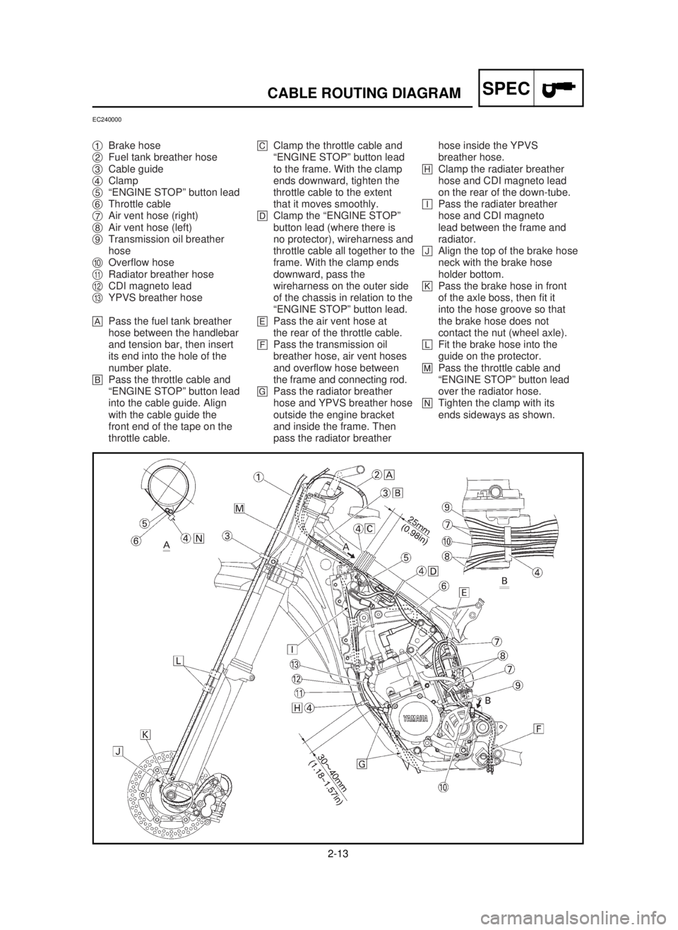
1Brake hose
2Fuel tank breather hose
3Cable guide
4Clamp
5“ENGINE STOP” button lead
6Throttle cable
7Air vent hose (right)
8Air vent hose (left)
9Transmission oil breather
hose
0Overflow hose
qRadiator breather hose
wCDI magneto lead
eYPVS breather hose
APass the fuel tank breather
hose between the handlebar
and tension bar, then insert
its end into the hole of the
number plate.
BPass the throttle cable and
“ENGINE STOP” button lead
into the cable guide. Align
with the cable guide the
front end of the tape on the
throttle cable.CClamp the throttle cable and
“ENGINE STOP” button lead
to the frame. With the clamp
ends downward, tighten the
throttle cable to the extent
that it moves smoothly.
DClamp the “ENGINE STOP”
button lead (where there is
no protector), wireharness and
throttle cable all together to the
frame. With the clamp ends
downward, pass the
wireharness on the outer side
of the chassis in relation to the
“ENGINE STOP” button lead.
EPass the air vent hose at
the rear of the throttle cable.
FPass the transmission oil
breather hose, air vent hoses
and overflow hose between
the frame and connecting rod.
GPass the radiator breather
hose and YPVS breather hose
outside the engine bracket
and inside the frame. Then
pass the radiator breather hose inside the YPVS
breather hose.
HClamp the radiater breather
hose and CDI magneto lead
on the rear of the down-tube.
IPass the radiater breather
hose and CDI magneto
lead between the frame and
radiator.
JAlign the top of the brake hose
neck with the brake hose
holder bottom.
KPass the brake hose in front
of the axle boss, then fit it
into the hose groove so that
the brake hose does not
contact the nut (wheel axle).
LFit the brake hose into the
guide on the protector.
MPass the throttle cable and
“ENGINE STOP” button lead
over the radiator hose.
NTighten the clamp with its
ends sideways as shown.
5MV-9-30-2B 6/19/00 1:14 PM Page 26
Page 118 of 558

2-14
SPECCABLE ROUTING DIAGRAM
1Brake hose holder
2Master cylinder
3Brake hose
4Hose guide
5CDI unit band
6CDI unit
7High tension cord
8Ignition coil
9Cable guide
0Radiator breather hose
qWireharness
w“ENGINE STOP” button lead
eCDI magneto lead
rClutch cable
tClamp
yCDI unit bracket
uEngine bracket
iCDI unit damper
APass the brake hose into
the brake hose holder.BIf the brake hose contacts
the spring (rear shock
absorber), correct its twist.
CInstall the brake hose so that
its pipe portion directs as
shown and lightly touches
the projection on the master
cylinder.
DPass the reservoir hose
between the brake hose and
swingarm bracket.
EPut the CDI unit fully in
the CDI unit band.
FFasten the ground lead
together with the ignition
coil.
GPass the cluch cable into
the cable guide.
HClamp the CDI magneto lead
on the upper part of
the frame gusset at its
protecting tube.IPass the clutch cable over
the radiator hose.
JClamp the wireharness on
the top of the CDI unit with
the clamp end downward.
KCut the clamp end to be flush
with CDI unit side.
LFit the CDI unit band over
the CDI unit bracket till it
stops.
MInstall the brake hose to
the caliper with the paint on
the pipe facing the caliper
and with the pipe contacting
the caliper projection.
NPass the radiator breather
hose between the frame and
radiator hose so that it is not
kinked or wedged.
OPosition the CDI unit between
the engine brackets as
shown.
5MV-9-30-2B 6/19/00 1:14 PM Page 28