YAMAHA YZ125LC 2007 Manuale duso (in Italian)
Manufacturer: YAMAHA, Model Year: 2007, Model line: YZ125LC, Model: YAMAHA YZ125LC 2007Pages: 576, PDF Dimensioni: 14.15 MB
Page 401 of 576
5-19
CHAS
FREIN AVANT ET FREIN ARRIERE
VORDERRADBREMSE UND HINTERRADBREMSE
FRENO ANTERIORE E FRENO POSTERIORE
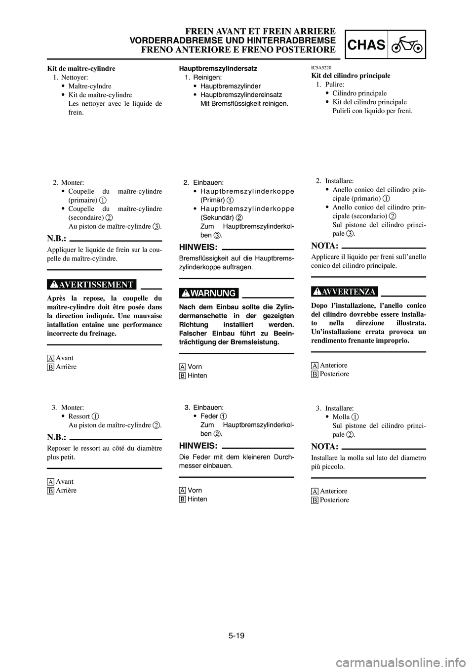
Hauptbremszylindersatz
1. Reinigen:
9Hauptbremszylinder
9Hauptbremszylindereinsatz
Mit Bremsflüssigkeit reinigen.
2. Einbauen:
9Hauptbremszylinderkoppe
(Primär) 1
9Hauptbremszylinderkoppe
(Sekundär) 2
Zum Hauptbremszylinderkol-
ben 3.
HINWEIS:
Bremsflüssigkeit auf die Hauptbrems-
zylinderkoppe auftragen.
W
Nach dem Einbau sollte die Zylin-
dermanschette in der gezeigten
Richtung installiert werden.
Falscher Einbau führt zu Beein-
trächtigung der Bremsleistung.
AVorn
BHinten
Kit de maître-cylindre
1. Nettoyer:
9Maître-cylndre
9Kit de maître-cylindre
Les nettoyer avec le liquide de
frein.
2. Monter:
9Coupelle du maître-cylindre
(primaire) 1
9Coupelle du maître-cylindre
(secondaire) 2
Au piston de maître-cylindre 3.
N.B.:
Appliquer le liquide de frein sur la cou-
pelle du maître-cylindre.
XG
Après la repose, la coupelle du
maître-cylindre doit être posée dans
la direction indiquée. Une mauvaise
intallation entaîne une performance
incorrecte du freinage.
AAvant
BArrière
IC5A5220
Kit del cilindro principale
1. Pulire:
9Cilindro principale
9Kit del cilindro principale
Pulirli con liquido per freni.
2. Installare:
9Anello conico del cilindro prin-
cipale (primario) 1
9Anello conico del cilindro prin-
cipale (secondario) 2
Sul pistone del cilindro princi-
pale 3.
NOTA:
Applicare il liquido per freni sull’anello
conico del cilindro principale.
T
Dopo l’installazione, l’anello conico
del cilindro dovrebbe essere installa-
to nella direzione illustrata.
Un’installazione errata provoca un
rendimento frenante improprio.
AAnteriore
BPosteriore
3. Einbauen:
9Feder 1
Zum Hauptbremszylinderkol-
ben 2.
HINWEIS:
Die Feder mit dem kleineren Durch-
messer einbauen.
AVorn
BHinten
3. Monter:
9Ressort 1
Au piston de maître-cylindre 2.
N.B.:
Reposer le ressort au côté du diamètre
plus petit.
AAvant
BArrière3. Installare:
9Molla 1
Sul pistone del cilindro princi-
pale 2.
NOTA:
Installare la molla sul lato del diametro
più piccolo.
AAnteriore
BPosteriore
1C3-9-32-5A 4/7/06 2:45 PM Page 39
Page 402 of 576
![YAMAHA YZ125LC 2007 Manuale duso (in Italian) 5-20
CHASFRONT BRAKE AND REAR BRAKE
4. Install:
[Front]
9Master cylinder kit 1
9Plain washer 2
9Circlip 3
9Master cylinder boot 4
To master cylinder 5.
[Rear]
9Master cylinder kit 1
9Push rod 2
9Circ YAMAHA YZ125LC 2007 Manuale duso (in Italian) 5-20
CHASFRONT BRAKE AND REAR BRAKE
4. Install:
[Front]
9Master cylinder kit 1
9Plain washer 2
9Circlip 3
9Master cylinder boot 4
To master cylinder 5.
[Rear]
9Master cylinder kit 1
9Push rod 2
9Circ](/img/51/53915/w960_53915-401.png)
5-20
CHASFRONT BRAKE AND REAR BRAKE
4. Install:
[Front]
9Master cylinder kit 1
9Plain washer 2
9Circlip 3
9Master cylinder boot 4
To master cylinder 5.
[Rear]
9Master cylinder kit 1
9Push rod 2
9Circlip 3
9Master cylinder boot 4
To master cylinder 5.
NOTE:
9Apply the brake fluid on the master cylinder
kit.
9Apply the lithium soap base grease on the tip
of the push rod.
9When installing the circlip, use a long nose
circlip pliers.
AFront
BRear
EC5A5310
Front master cylinder
1. Install:
9Master cylinder 1
9Master cylinder bracket 2
9Bolt (master cylinder bracket) 3
NOTE:
9Install the bracket so that the arrow mark a
face upward.
9First tighten the bolts on the upper side of the
master cylinder bracket, and then tighten the
bolts on the lower side.
9 Nm (0.9 m•kg, 6.5 ft•lb)
2. Install:
9Brake lever 1
9Bolt (brake lever) 2
9Nut (brake lever) 3
NOTE:
Apply the lithium soap base grease on the
brake lever sliding surface, bolt and contacting
surface of the master cylinder piston.
6 Nm (0.6 m•kg, 4.3 ft•lb)
6 Nm (0.6 m•kg, 4.3 ft•lb)
1C3-9-32-5A 4/7/06 2:45 PM Page 40
Page 403 of 576
![YAMAHA YZ125LC 2007 Manuale duso (in Italian) 5-20
CHAS
FREIN AVANT ET FREIN ARRIERE
VORDERRADBREMSE UND HINTERRADBREMSE
FRENO ANTERIORE E FRENO POSTERIORE
4. Monter:
[Avant]
9Kit de maître-cylindre 1
9Rondelle ordinaire 2
9Circlip 3
9Soufflet d YAMAHA YZ125LC 2007 Manuale duso (in Italian) 5-20
CHAS
FREIN AVANT ET FREIN ARRIERE
VORDERRADBREMSE UND HINTERRADBREMSE
FRENO ANTERIORE E FRENO POSTERIORE
4. Monter:
[Avant]
9Kit de maître-cylindre 1
9Rondelle ordinaire 2
9Circlip 3
9Soufflet d](/img/51/53915/w960_53915-402.png)
5-20
CHAS
FREIN AVANT ET FREIN ARRIERE
VORDERRADBREMSE UND HINTERRADBREMSE
FRENO ANTERIORE E FRENO POSTERIORE
4. Monter:
[Avant]
9Kit de maître-cylindre 1
9Rondelle ordinaire 2
9Circlip 3
9Soufflet de maître-cylindre 4
Au maître-cylindre 5.
[Arrière]
9Kit de maître-cylindre 1
9Champignon de débrayage 2
9Circlip 3
9Soufflet de maître-cylindre 4
Au maître-cylindre 5.
N.B.:
9Appliquer le liquide de frein sur
l’ensemble du maître-cylindre.
9Appliquer de la graisse au lithium sur
l’extrémité du champignon de
débrayage.
9Pour mettre le circlip en place, utiliser
des pinces de circlip à long nez.
AAvant
BArrière
Maître-cylindre avant
1. Monter:
9Maître-cylindre 1
9Etrier de maître-cylindre 2
9Boulon (étrier de maître-
cylindre) 3
N.B.:
9Reposer le support pour que la flèche
asoit dirigée vers le haut.
9Serrer d’abord les boulons sur le côté
supérieur de l’étrier de maître-
cylindre, puis serrer les boulons sur le
côté inférieur.
4. Einbauen:
[Vorn]
9Hauptbremszylindersatz 1
9Unterlegscheibe 2
9Sprengring 3
9Manschette des Hauptbrems-
zylinders 4
Zum Hauptbremszylinder 5.
[Hinten]
9Hauptbremszylindereinsatz 1
9Schubstange 2
9Sprengring 3
9Manschette des Hauptbrems-
zylinders 4
Zum Hauptbremszylinder 5.
HINWEIS:
9Bremsflüssigkeit auf dem Haupt-
bremszylindersatz auftragen.
9Lithiumseifen-Fett am Ende der
Schubstange auftragen.
9Beim Einbauen des Sprengrings
eine Sprengringzange verwenden.
AVorn
BHinten
Vorderrad-Hauptbremszylinder
1. Einbauen:
9Hauptbremszylinder 1
9Hauptbremszylinderhalterung 2
9Schraube (Hauptbremszylin-
derhalterung) 3
HINWEIS:
9Die Halterung so einbauen, dass die
Pfeilmarkierung anach oben
gerichtet ist.
9Zuerst die Schrauben an der Ober-
seite der Hauptbremszylinderhalte-
rung und danach die Schrauben an
der Unterseite festziehen.
4. Installare:
[Anteriormente]
9Kit del cilindro principale 1
9Rosetta 2
9Anello elastico di arresto 3
9Protezione del cilindro principa-
le 4
Sul cilindro principale 5.
[Posteriormente]
9Kit del cilindro principale 1
9Asta di comando 2
9Anello elastico di arresto 3
9Protezione del cilindro principa-
le 4
Sul cilindro principale 5.
NOTA:
9Applicare il liquido per freni sul kit
del cilindro principale.
9Applicare sulla punta dell’asta di
comando il grasso a base di sapone di
litio.
9Quando si installa l’anello elastico di
arresto, usare pinze ad ago per anelli
elastici di arresto.
AAnteriore
BPosteriore
IC5A5310
Cilindro principale anteriore
1. Installare:
9Cilindro principale 1
9Staffa del cilindro principale 2
9Bullone (staffa del cilindro prin-
cipale) 3
NOTA:
9Installare la staffa in modo che la
freccia asia rivolta verso l’alto.
9Serrare dapprima i bulloni sul lato
superiore della staffa del cilindro prin-
cipale e poi serrare i bulloni sul lato
inferiore.
9 Nm (0,9 m•kg, 6,5 ft•lb)
9 Nm (0,9 m•kg, 6,5 ft•lb)
9 Nm (0,9 m•kg, 6,5 ft•lb)
2. Einbauen:
9Bremshebel 1
9Schraube (Bremshebel) 2
9Mutter (Bremshebel) 3
HINWEIS:
Lithiumseifenfett an der Bremshebel-
gleitfläche, an der Schraube und an
der Kontaktfläche des Hauptbremszy-
linders auftragen.
2. Monter:
9Levier de frein 1
9Boulon (levier de frein) 2
9Ecrou (levier de frein) 3
N.B.:
Appliquer de la graisse à base de savon
au lithium sur la surface de coulisse-
ment du levier de frein, sur le boulon et
sur la surface de contact du maître-
cylindre.
2. Installare:
9Leva di comando del freno 1
9Bullone (leva di comando del
freno) 2
9Dado (leva di comando del
freno) 3
NOTA:
Applicare il grasso a base di sapone di
litio sulla superficie di scorrimento
della leva del freno, il bullone e la
superficie di contatto del pistone del
cilindro principale.
6 Nm (0,6 m•kg, 4,3 ft•lb)6 Nm (0,6 m•kg, 4,3 ft•lb)6 Nm (0,6 m•kg, 4,3 ft•lb)
6 Nm (0,6 m•kg, 4,3 ft•lb)6 Nm (0,6 m•kg, 4,3 ft•lb)
6 Nm (0,6 m•kg, 4,3 ft•lb)
1C3-9-32-5A 4/7/06 2:45 PM Page 41
Page 404 of 576
5-21
CHASFRONT BRAKE AND REAR BRAKE
EC5A5401
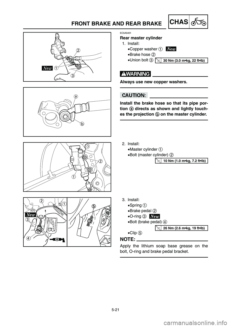
Rear master cylinder
1. Install:
9Copper washer 1
9Brake hose 2
9Union bolt 3
w
Always use new copper washers.
cC
Install the brake hose so that its pipe por-
tion
a adirects as shown and lightly touch-
es the projection
b bon the master cylinder.
30 Nm (3.0 m•kg, 22 ft•lb)
2. Install:
9Master cylinder 1
9Bolt (master cylinder) 2
10 Nm (1.0 m•kg, 7.2 ft•lb)
3. Install:
9Spring 1
9Brake pedal 2
9O-ring 3
9Bolt (brake pedal) 4
9Clip 5
NOTE:
Apply the lithium soap base grease on the
bolt, O-ring and brake pedal bracket.
26 Nm (2.6 m•kg, 19 ft•lb)
1C3-9-32-5A 4/7/06 2:45 PM Page 42
Page 405 of 576
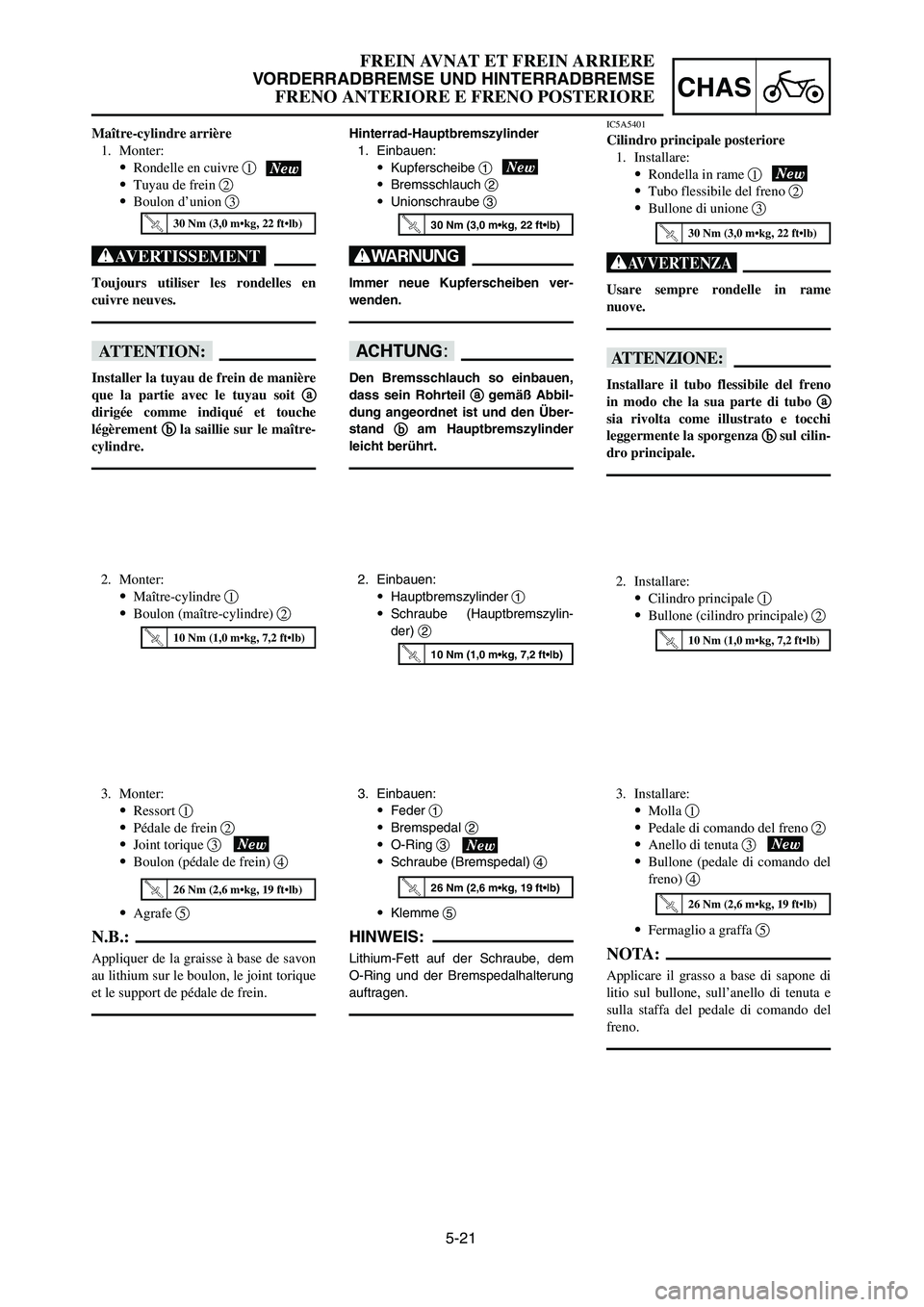
3. Einbauen:
9Feder 1
9Bremspedal 2
9O-Ring 3
9Schraube (Bremspedal) 4
9Klemme 5
HINWEIS:
Lithium-Fett auf der Schraube, dem
O-Ring und der Bremspedalhalterung
auftragen.
5-21
CHAS
FREIN AVNAT ET FREIN ARRIERE
VORDERRADBREMSE UND HINTERRADBREMSE
FRENO ANTERIORE E FRENO POSTERIORE
Maître-cylindre arrière
1. Monter:
9Rondelle en cuivre 1
9Tuyau de frein 2
9Boulon d’union 3
XG
Toujours utiliser les rondelles en
cuivre neuves.
fF
Installer la tuyau de frein de manière
que la partie avec le tuyau soit a a
dirigée comme indiqué et touche
légèrement b b
la saillie sur le maître-
cylindre.
2. Monter:
9Maître-cylindre 1
9Boulon (maître-cylindre) 2
Hinterrad-Hauptbremszylinder
1. Einbauen:
9Kupferscheibe 1
9Bremsschlauch 2
9Unionschraube 3
W
Immer neue Kupferscheiben ver-
wenden.
dD
Den Bremsschlauch so einbauen,
dass sein Rohrteil a a
gemäß Abbil-
dung angeordnet ist und den Über-
stand b b
am Hauptbremszylinder
leicht berührt.
2. Einbauen:
9Hauptbremszylinder 1
9Schraube (Hauptbremszylin-
der) 2
IC5A5401
Cilindro principale posteriore
1. Installare:
9Rondella in rame 1
9Tubo flessibile del freno 2
9Bullone di unione 3
T
Usare sempre rondelle in rame
nuove.
iI
Installare il tubo flessibile del freno
in modo che la sua parte di tubo a a
sia rivolta come illustrato e tocchi
leggermente la sporgenza b b
sul cilin-
dro principale.
2. Installare:
9Cilindro principale 1
9Bullone (cilindro principale) 2
10 Nm (1,0 m•kg, 7,2 ft•lb)
30 Nm (3,0 m•kg, 22 ft•lb)30 Nm (3,0 m•kg, 22 ft•lb)30 Nm (3,0 m•kg, 22 ft•lb)
10 Nm (1,0 m•kg, 7,2 ft•lb)10 Nm (1,0 m•kg, 7,2 ft•lb)
26 Nm (2,6 m•kg, 19 ft•lb)
26 Nm (2,6 m•kg, 19 ft•lb)
3. Monter:
9Ressort 1
9Pédale de frein 2
9Joint torique 3
9Boulon (pédale de frein) 4
9Agrafe 5
N.B.:
Appliquer de la graisse à base de savon
au lithium sur le boulon, le joint torique
et le support de pédale de frein.
26 Nm (2,6 m•kg, 19 ft•lb)
3. Installare:
9Molla 1
9Pedale di comando del freno 2
9Anello di tenuta 3
9Bullone (pedale di comando del
freno) 4
9Fermaglio a graffa 5
NOTA:
Applicare il grasso a base di sapone di
litio sul bullone, sull’anello di tenuta e
sulla staffa del pedale di comando del
freno.
1C3-9-32-5A 4/7/06 2:45 PM Page 43
Page 406 of 576
5-22
CHASFRONT BRAKE AND REAR BRAKE
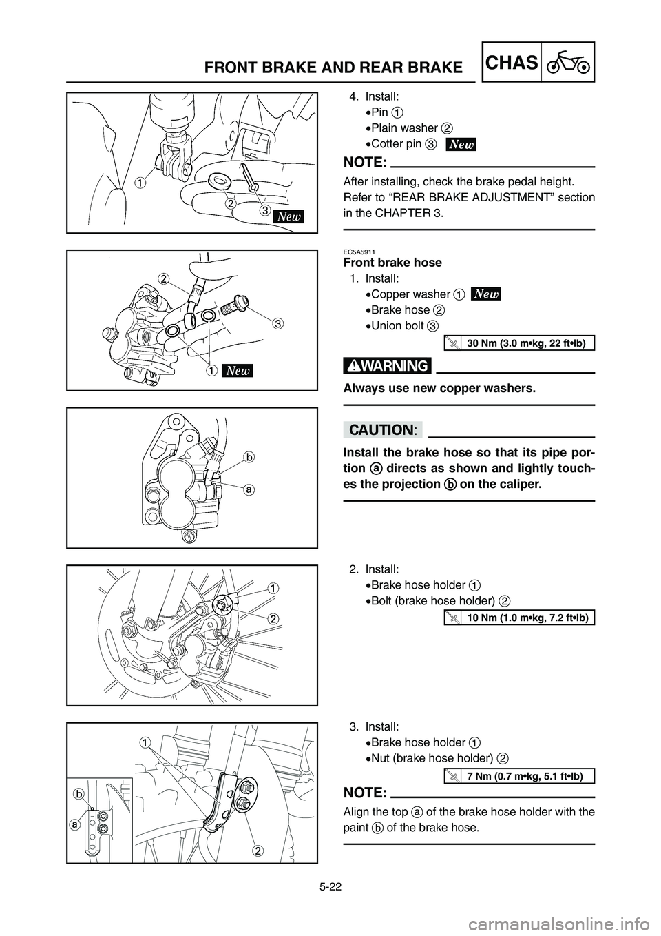
2. Install:
9Brake hose holder 1
9Bolt (brake hose holder) 2
3. Install:
9Brake hose holder 1
9Nut (brake hose holder) 2
NOTE:
Align the top aof the brake hose holder with the
paint bof the brake hose.
10 Nm (1.0 m•kg, 7.2 ft•lb)
7 Nm (0.7 m•kg, 5.1 ft•lb)
4. Install:
9Pin 1
9Plain washer 2
9Cotter pin 3
NOTE:
After installing, check the brake pedal height.
Refer to “REAR BRAKE ADJUSTMENT” section
in the CHAPTER 3.
EC5A5911
Front brake hose
1. Install:
9Copper washer 1
9Brake hose 2
9Union bolt 3
w
Always use new copper washers.
cC
Install the brake hose so that its pipe por-
tion a a
directs as shown and lightly touch-
es the projection b b
on the caliper.
30 Nm (3.0 m•kg, 22 ft•lb)
1C3-9-32-5A 4/7/06 2:45 PM Page 44
Page 407 of 576
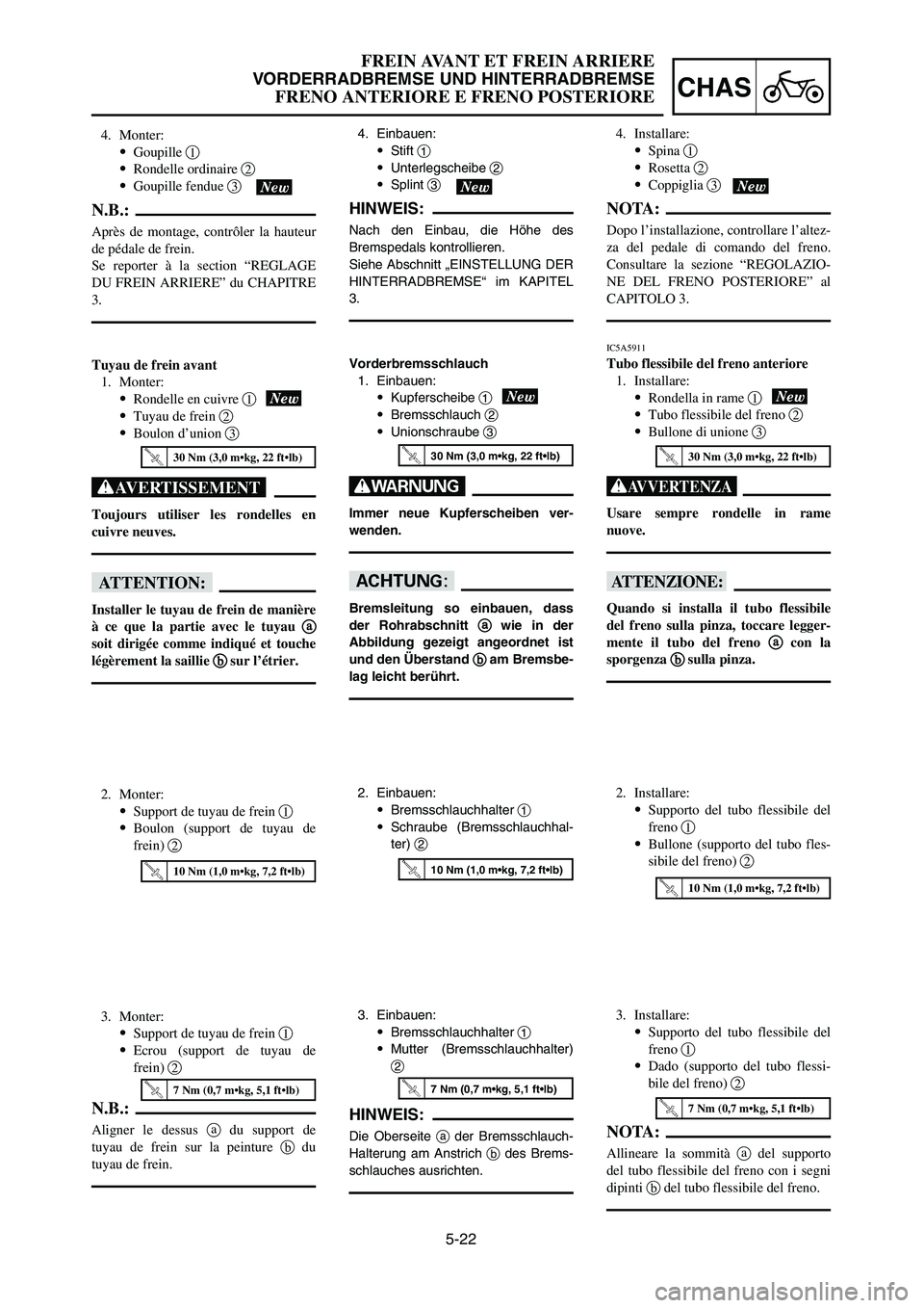
5-22
CHAS
FREIN AVANT ET FREIN ARRIERE
VORDERRADBREMSE UND HINTERRADBREMSE
FRENO ANTERIORE E FRENO POSTERIORE
4. Monter:
9Goupille 1
9Rondelle ordinaire 2
9Goupille fendue 3
N.B.:
Après de montage, contrôler la hauteur
de pédale de frein.
Se reporter à la section “REGLAGE
DU FREIN ARRIERE” du CHAPITRE
3.
Tuyau de frein avant
1. Monter:
9Rondelle en cuivre 1
9Tuyau de frein 2
9Boulon d’union 3
XG
Toujours utiliser les rondelles en
cuivre neuves.
fF
Installer le tuyau de frein de manière
à ce que la partie avec le tuyau a a
soit dirigée comme indiqué et touche
légèrement la saillie b b
sur l’étrier.
2. Monter:
9Support de tuyau de frein 1
9Boulon (support de tuyau de
frein) 2
3. Monter:
9Support de tuyau de frein 1
9Ecrou (support de tuyau de
frein) 2
N.B.:
Aligner le dessus adu support de
tuyau de frein sur la peinture bdu
tuyau de frein.
4. Einbauen:
9Stift 1
9Unterlegscheibe 2
9Splint 3
HINWEIS:
Nach den Einbau, die Höhe des
Bremspedals kontrollieren.
Siehe Abschnitt „EINSTELLUNG DER
HINTERRADBREMSE“ im KAPITEL
3.
Vorderbremsschlauch
1. Einbauen:
9Kupferscheibe 1
9Bremsschlauch 2
9Unionschraube 3
W
Immer neue Kupferscheiben ver-
wenden.
dD
Bremsleitung so einbauen, dass
der Rohrabschnitt a a
wie in der
Abbildung gezeigt angeordnet ist
und den Überstand b b
am Bremsbe-
lag leicht berührt.
2. Einbauen:
9Bremsschlauchhalter 1
9Schraube (Bremsschlauchhal-
ter) 2
3. Einbauen:
9Bremsschlauchhalter 1
9Mutter (Bremsschlauchhalter)
2
HINWEIS:
Die Oberseite ader Bremsschlauch-
Halterung am Anstrich bdes Brems-
schlauches ausrichten.
4. Installare:
9Spina 1
9Rosetta 2
9Coppiglia 3
NOTA:
Dopo l’installazione, controllare l’altez-
za del pedale di comando del freno.
Consultare la sezione “REGOLAZIO-
NE DEL FRENO POSTERIORE” al
CAPITOLO 3.
IC5A5911
Tubo flessibile del freno anteriore
1. Installare:
9Rondella in rame 1
9Tubo flessibile del freno 2
9Bullone di unione 3
T
Usare sempre rondelle in rame
nuove.
iI
Quando si installa il tubo flessibile
del freno sulla pinza, toccare legger-
mente il tubo del freno a a
con la
sporgenza b b
sulla pinza.
2. Installare:
9Supporto del tubo flessibile del
freno 1
9Bullone (supporto del tubo fles-
sibile del freno) 2
3. Installare:
9Supporto del tubo flessibile del
freno 1
9Dado (supporto del tubo flessi-
bile del freno) 2
NOTA:
Allineare la sommità adel supporto
del tubo flessibile del freno con i segni
dipinti bdel tubo flessibile del freno.
10 Nm (1,0 m•kg, 7,2 ft•lb)10 Nm (1,0 m•kg, 7,2 ft•lb)
10 Nm (1,0 m•kg, 7,2 ft•lb)
7 Nm (0,7 m•kg, 5,1 ft•lb)7 Nm (0,7 m•kg, 5,1 ft•lb)
7 Nm (0,7 m•kg, 5,1 ft•lb)
30 Nm (3,0 m•kg, 22 ft•lb)30 Nm (3,0 m•kg, 22 ft•lb)30 Nm (3,0 m•kg, 22 ft•lb)
1C3-9-32-5A 4/7/06 2:45 PM Page 45
Page 408 of 576
5-23
CHASFRONT BRAKE AND REAR BRAKE
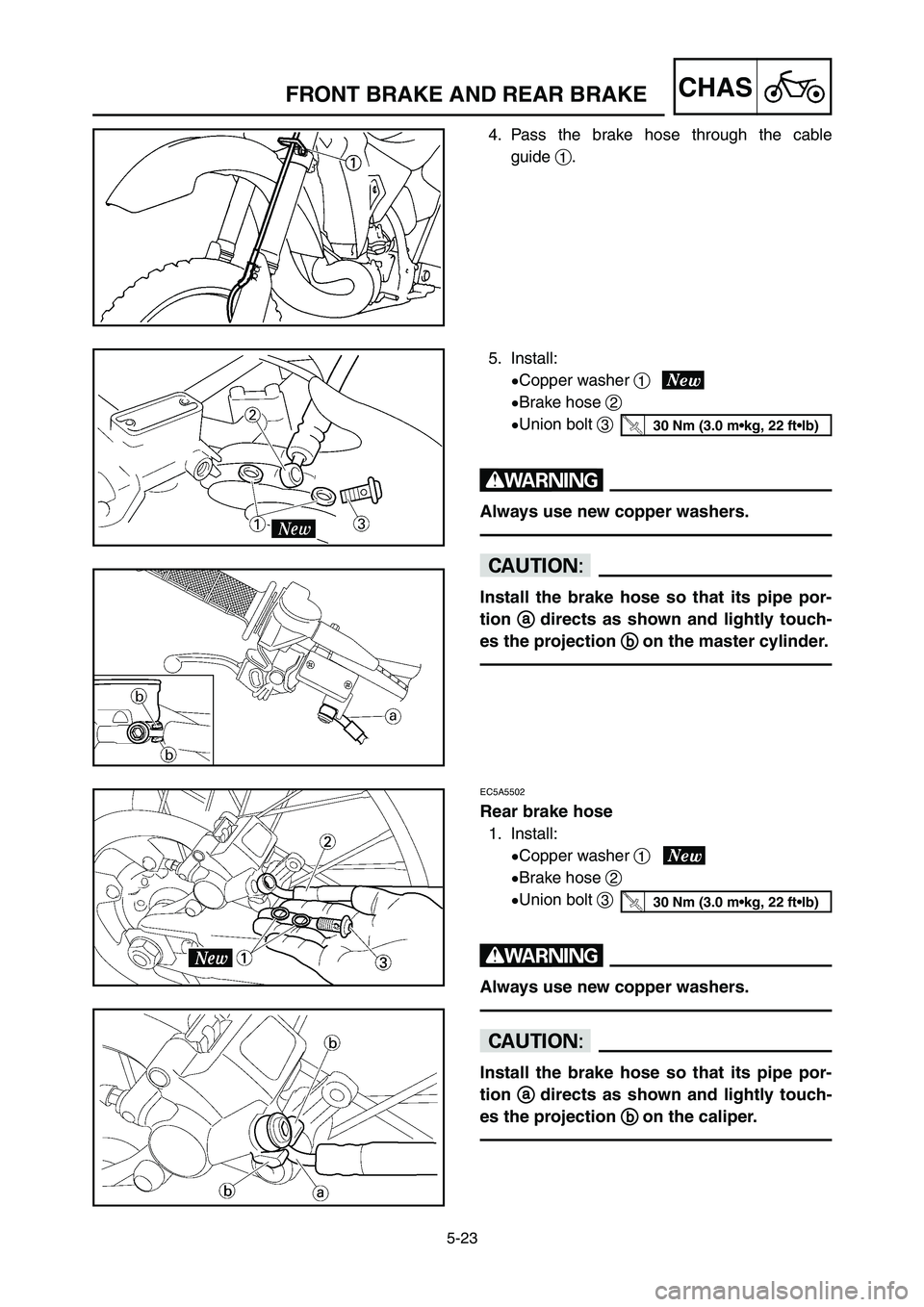
4. Pass the brake hose through the cable
guide 1.
5. Install:
9Copper washer 1
9Brake hose 2
9Union bolt 3
w
Always use new copper washers.
cC
Install the brake hose so that its pipe por-
tion a a
directs as shown and lightly touch-
es the projection b b
on the master cylinder.
30 Nm (3.0 m•kg, 22 ft•lb)
EC5A5502
Rear brake hose
1. Install:
9Copper washer 1
9Brake hose 2
9Union bolt 3
w
Always use new copper washers.
cC
Install the brake hose so that its pipe por-
tion a a
directs as shown and lightly touch-
es the projection b b
on the caliper.
30 Nm (3.0 m•kg, 22 ft•lb)
1C3-9-32-5A 4/7/06 2:45 PM Page 46
Page 409 of 576
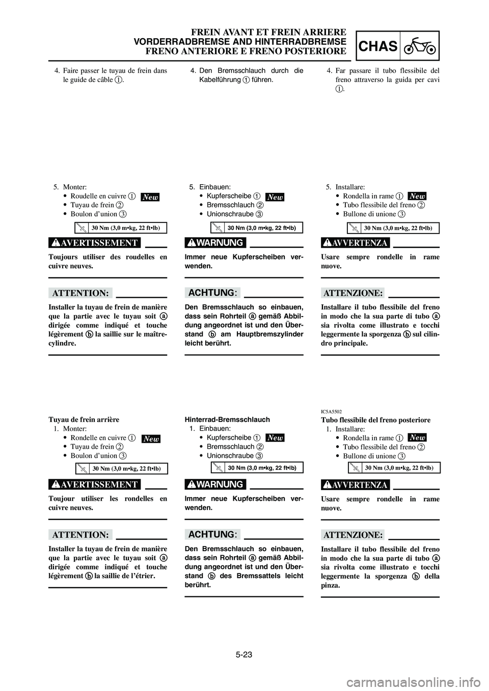
5-23
CHAS
FREIN AVANT ET FREIN ARRIERE
VORDERRADBREMSE AND HINTERRADBREMSE
FRENO ANTERIORE E FRENO POSTERIORE
4. Den Bremsschlauch durch die
Kabelführung 1führen.4. Faire passer le tuyau de frein dans
le guide de câble 1.4. Far passare il tubo flessibile del
freno attraverso la guida per cavi
1.
5. Monter:
9Roudelle en cuivre 1
9Tuyau de frein 2
9Boulon d’union 3
XG
Toujours utiliser des roudelles en
cuivre neuves.
fF
Installer la tuyau de frein de manière
que la partie avec le tuyau soit a a
dirigée comme indiqué et touche
légèrement b b
la saillie sur le maître-
cylindre.
5. Einbauen:
9Kupferscheibe 1
9Bremsschlauch 2
9Unionschraube 3
W
Immer neue Kupferscheiben ver-
wenden.
dD
Den Bremsschlauch so einbauen,
dass sein Rohrteil a a
gemäß Abbil-
dung angeordnet ist und den Über-
stand b b
am Hauptbremszylinder
leicht berührt.
5. Installare:
9Rondella in rame 1
9Tubo flessibile del freno 2
9Bullone di unione 3
T
Usare sempre rondelle in rame
nuove.
iI
Installare il tubo flessibile del freno
in modo che la sua parte di tubo a a
sia rivolta come illustrato e tocchi
leggermente la sporgenza b b
sul cilin-
dro principale.
Tuyau de frein arrière
1. Monter:
9Rondelle en cuivre 1
9Tuyau de frein 2
9Boulon d’union 3
XG
Toujour utiliser les rondelles en
cuivre neuves.
fF
Installer la tuyau de frein de manière
que la partie avec le tuyau soit a a
dirigée comme indiqué et touche
légèrement b b
la saillie de l’étrier.
Hinterrad-Bremsschlauch
1. Einbauen:
9Kupferscheibe 1
9Bremsschlauch 2
9Unionschraube 3
W
Immer neue Kupferscheiben ver-
wenden.
dD
Den Bremsschlauch so einbauen,
dass sein Rohrteil a a
gemäß Abbil-
dung angeordnet ist und den Über-
stand b b
des Bremssattels leicht
berührt.
IC5A5502
Tubo flessibile del freno posteriore
1. Installare:
9Rondella in rame 1
9Tubo flessibile del freno 2
9Bullone di unione 3
T
Usare sempre rondelle in rame
nuove.
iI
Installare il tubo flessibile del freno
in modo che la sua parte di tubo a a
sia rivolta come illustrato e tocchi
leggermente la sporgenza b b
della
pinza.
30 Nm (3,0 m•kg, 22 ft•lb)30 Nm (3,0 m•kg, 22 ft•lb)30 Nm (3,0 m•kg, 22 ft•lb)
30 Nm (3,0 m•kg, 22 ft•lb)30 Nm (3,0 m•kg, 22 ft•lb)30 Nm (3,0 m•kg, 22 ft•lb)
1C3-9-32-5A 4/7/06 2:45 PM Page 47
Page 410 of 576
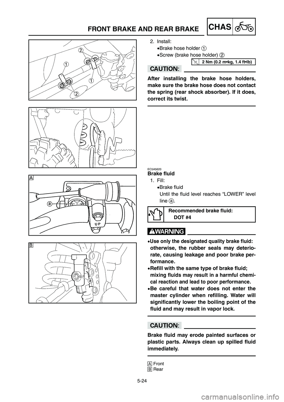
5-24
CHASFRONT BRAKE AND REAR BRAKE
2. Install:
9Brake hose holder 1
9Screw (brake hose holder) 2
cC
After installing the brake hose holders,
make sure the brake hose does not contact
the spring (rear shock absorber). If it does,
correct its twist.
EC5A5620
Brake fluid
1. Fill:
9Brake fluid
Until the fluid level reaches “LOWER” level
line a.
w
9Use only the designated quality brake fluid:
otherwise, the rubber seals may deterio-
rate, causing leakage and poor brake per-
formance.
9Refill with the same type of brake fluid;
mixing fluids may result in a harmful chemi-
cal reaction and lead to poor performance.
9Be careful that water does not enter the
master cylinder when refilling. Water will
significantly lower the boiling point of the
fluid and may result in vapor lock.
cC
Brake fluid may erode painted surfaces or
plastic parts. Always clean up spilled fluid
immediately.
AFront
BRear
Recommended brake fluid:
DOT #4
2 Nm (0.2 m•kg, 1.4 ft•lb)
1C3-9-32-5A 4/7/06 2:45 PM Page 48