check oil YAMAHA YZ125LC 2011 User Guide
[x] Cancel search | Manufacturer: YAMAHA, Model Year: 2011, Model line: YZ125LC, Model: YAMAHA YZ125LC 2011Pages: 166, PDF Size: 8.49 MB
Page 45 of 166

3-4
MAINTENANCE INTERVALS
TIRE, WHEELS
Inspect air pressure, wheel
run-out, tire wear and
spoke looseness●●
Retighten sprocket bolt●●
Inspect bearings●
Replace bearings●
Lubricate●Lithium base grease
THROTTLE, CONTROL CA-
BLE
Check routing and connec-
tion●●
Lubricate●●Yamaha cable lube or SAE
10W-40 motor oil ItemAfter
break-in
Every
race
(about
2.5
hours)Every
third
(about
7.5
hours)Every
fifth
(about
12.5
hours)
As re-
quiredRemarks
Page 46 of 166
3-5
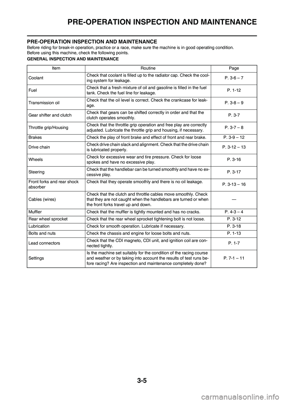
PRE-OPERATION INSPECTION AND MAINTENANCE
PRE-OPERATION INSPECTION AND MAINTENANCE
Before riding for break-in operation, practice or a race, make sure the machine is in good operating condition.
Before using this machine, check the following points.
GENERAL INSPECTION AND MAINTENANCE
Item Routine Page
CoolantCheck that coolant is filled up to the radiator cap. Check the cool-
ing system for leakage.P. 3-6 – 7
FuelCheck that a fresh mixture of oil and gasoline is filled in the fuel
tank. Check the fuel line for leakage.P. 1-12
Transmission oilCheck that the oil level is correct. Check the crankcase for leak-
age.P. 3-8 – 9
Gear shifter and clutchCheck that gears can be shifted correctly in order and that the
clutch operates smoothly.P. 3-7
Throttle grip/HousingCheck that the throttle grip operation and free play are correctly
adjusted. Lubricate the throttle grip and housing, if necessary.P. 3-7 – 8
Brakes Check the play of front brake and effect of front and rear brake. P. 3-9 – 12
Drive chainCheck drive chain slack and alignment. Check that the drive chain
is lubricated properly.P. 3-12 – 13
WheelsCheck for excessive wear and tire pressure. Check for loose
spokes and have no excessive play.P. 3-16
SteeringCheck that the handlebar can be turned smoothly and have no ex-
cessive play.P. 3-17
Front forks and rear shock
absorberCheck that they operate smoothly and there is no oil leakage.
P. 3-13 – 16
Cables (wires)Check that the clutch and throttle cables move smoothly. Check
that they are not caught when the handlebars are turned or when
the front forks travel up and down.—
Muffler Check that the muffler is tightly mounted and has no cracks. P. 4-3 – 4
Rear wheel sprocket Check that the rear wheel sprocket tightening bolt is not loose. P. 3-12
Lubrication Check for smooth operation. Lubricate if necessary. P. 3-18
Bolts and nuts Check the chassis and engine for loose bolts and nuts. P. 1-13
Lead connectorsCheck that the CDI magneto, CDI unit, and ignition coil are con-
nected tightly.P. 1-7
SettingsIs the machine set suitably for the condition of the racing course
and weather or by taking into account the results of test runs be-
fore racing? Are inspection and maintenance completely done?P. 7-1 – 11
Page 47 of 166

3-6
ENGINE
ENGINE
CHECKING THE COOLANT LEVEL
Do not remove the radiator cap
"1", drain bolt and hoses when the
engine and radiator are hot. Scald-
ing hot fluid and steam may be
blown out under pressure, which
could cause serious injury. When
the engine has cooled, place a
thick towel over the radiator cap,
slowly rotate the cap counter-
clockwise to the detent. This pro-
cedure allows any residual
pressure to escape. When the
hissing sound has stopped, press
down on the cap while turning
counterclockwise and remove it.
Hard water or salt water is harmful
to the engine parts. You may use
distilled water, if you can't get soft
water.
1. Place the machine on a level
place, and hold it in an upright po-
sition.
2. Remove:
• Radiator cap
3. Check:
• Coolant level "a"
Coolant level low→Add coolant.
1. Radiator
CHANGING THE COOLANT
Do not remove the radiator cap
when the engine is hot.
Take care so that coolant does not
splash on painted surfaces. If it
splashes, wash it away with water.
1. Place a container under the en-
gine.
2. Remove:
• Coolant drain bolt "1"
3. Remove:
• Radiator cap
Drain the coolant completely.
4. Clean:
• Cooling system
Thoroughly flush the cooling sys-
tem with clean tap water.
5. Install:
• Copper washer
• Coolant drain bolt
6. Fill:
• Radiator
•Engine
To specified level.
• Do not mix more than one type of
ethylene glycol antifreeze con-
taining corrosion inhibitors for
aluminum engine.
• Do not use water containing im-
purities or oil.
Handling notes of coolant:
The coolant is harmful so it should be
handled with special care.
• When coolant splashes to your
eye.
Thoroughly wash your eye with
water and see your doctor.
• When coolant splashes to your
clothes.
Quickly wash it away with water
and then with soap.
• When coolant is swallowed.
Quickly make him vomit and take
him to a doctor.
7. Install:
• Radiator cap
Start the engine and warm it up
for a several minutes.
8. Check:
• Coolant level
Coolant level low→Add coolant.
CHECKING THE RADIATOR CAP
1. Inspect:
• Seal (radiator cap) "1"
• Valve and valve seat "2"
Crack/damage→Replace.
Exist fur deposits "3" →Clean or
replace.
CHECKING THE RADIATOR CAP
OPENING PRESSURE
1. Attach:
• Radiator cap tester "1" and adapt-
er "2"
Apply water on the radiator cap seal.
Coolant drain bolt:
10 Nm (1.0 m•kg, 7.2
ft•lb)
Recommended coolant:
High quality ethylene
glycol anti-freeze con-
taining anti-corrosion
for aluminum engine
Coolant "1" and water
(soft water) "2" mixing ra-
tio:
50%/50%
Coolant capacity:
0.9 L (0.79 Imp qt, 0.95
US qt)
Radiator cap tester:
YU-24460-01/90890-
01325
Radiator cap tester
adapter:
YU-33984/90890-01352
Page 49 of 166

3-8
ENGINE
LUBRICATING THE THROTTLE
1. Remove:
• Cap cover "1"
• Throttle cable cap "2"
2. Apply:
• Lithium soap base grease
On the throttle cable end "a", tube
guide cable winding portion "b"
and roller sliding surface "c".
3. Install:
• Throttle cable cap
• Cap cover
CLEANING THE AIR FILTER
ELEMENT
Proper air filter maintenance is the
biggest key to preventing premature
engine wear and damage.
Never run the engine without the
air filter element in place; this
would allow dirt and dust to enter
the engine and cause rapid wear
and possible engine damage.
1. Remove:
• Seat
• Fitting bolt "1"
• Washer "2"
• Air filter element "3"
• Air filter guide "4"2. Clean:
• Air filter element
Clean them with solvent.
After cleaning, remove the remaining
solvent by squeezing the element.
• Do not twist the element when
squeezing the element.
• Leaving too much of solvent in
the element may result in poor
starting.
3. Inspect:
• Air filter element
Damage→Replace.
4. Apply:
• Foam-air-filter oil or equivalent oil
to the element
Squeeze out the excess oil. Element
should be wet but not dripping.
5. Install:
• Air filter guide "1"
Align the projection "a" on filter guide
with the hole "b" in air filter element.
6. Apply:
• Lithium soap base grease
On the matching surface "a" on air
filter element.7. Install:
• Air filter element "1"
• Washer
• Fitting bolt
Align the projection "a" on filter guide
with the hole "b" in air filter case.
CHECKING THE TRANSMISSION
OIL LEVEL
1. Start the engine, warm it up for
several minutes and wait for five
minutes.
2. Place the machine on a level
place and hold it up on upright po-
sition by placing the suitable
stand under the engine.
3. Check:
• Transmission oil level
Transmission oil level checking
steps:
a. Remove the oil check bolt "1".
b. Inspect the oil level.
Be sure the machine is positioned
straight up when inspecting the oil
level.
Never attempt to remove the oil
check bolt just after high speed
operation. The heated oil could
spout out, causing danger. Wait
until the oil cools down.
Oil flows out→Oil level is correct.
Oil does not flow out→Oil level is
low. Add transmission oil until oil
flows out. Throttle cable cap:
1 Nm (0.1 m•kg, 0.7
ft•lb)
Fitting bolt:
2 Nm (0.2 m•kg, 1.4
ft•lb)
Recommended brand:
YAMALUBE
Recommended engine
oil type
SAE10W-40
Recommended engine
oil grade
API service SG type or
higher
JASO standard MA
Page 50 of 166
3-9
CHASSIS
c. Inspect the gasket (oil check bolt),
replace if damaged.
d. Tighten the oil check bolt.
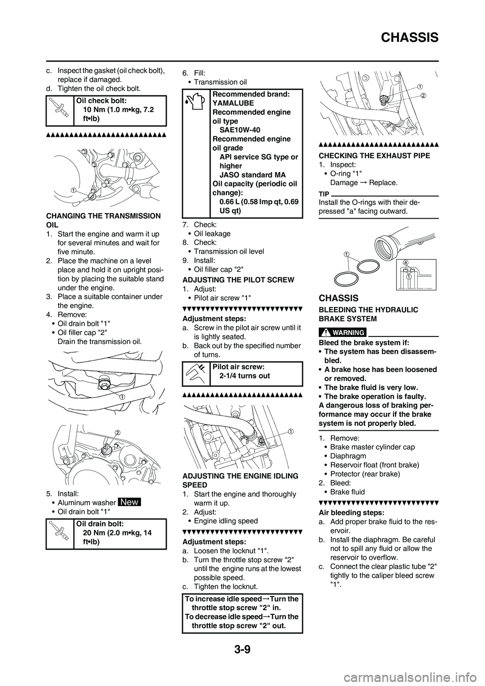
CHANGING THE TRANSMISSION
OIL
1. Start the engine and warm it up
for several minutes and wait for
five minute.
2. Place the machine on a level
place and hold it on upright posi-
tion by placing the suitable stand
under the engine.
3. Place a suitable container under
the engine.
4. Remove:
• Oil drain bolt "1"
• Oil filler cap "2"
Drain the transmission oil.
5. Install:
• Aluminum washer
• Oil drain bolt "1"6. Fill:
• Transmission oil
7. Check:
• Oil leakage
8. Check:
• Transmission oil level
9. Install:
• Oil filler cap "2"
ADJUSTING THE PILOT SCREW
1. Adjust:
• Pilot air screw "1"
Adjustment steps:
a. Screw in the pilot air screw until it
is lightly seated.
b. Back out by the specified number
of turns.
ADJUSTING THE ENGINE IDLING
SPEED
1. Start the engine and thoroughly
warm it up.
2. Adjust:
• Engine idling speed
Adjustment steps:
a. Loosen the locknut "1".
b. Turn the throttle stop screw "2"
until the engine runs at the lowest
possible speed.
c. Tighten the locknut.
CHECKING THE EXHAUST PIPE
1. Inspect:
• O-ring "1"
Damage→Replace.
Install the O-rings with their de-
pressed "a" facing outward.
CHASSIS
BLEEDING THE HYDRAULIC
BRAKE SYSTEM
Bleed the brake system if:
• The system has been disassem-
bled.
• A brake hose has been loosened
or removed.
• The brake fluid is very low.
• The brake operation is faulty.
A dangerous loss of braking per-
formance may occur if the brake
system is not properly bled.
1. Remove:
• Brake master cylinder cap
• Diaphragm
• Reservoir float (front brake)
• Protector (rear brake)
2. Bleed:
• Brake fluid
Air bleeding steps:
a. Add proper brake fluid to the res-
ervoir.
b. Install the diaphragm. Be careful
not to spill any fluid or allow the
reservoir to overflow.
c. Connect the clear plastic tube "2"
tightly to the caliper bleed screw
"1". Oil check bolt:
10 Nm (1.0 m•kg, 7.2
ft•lb)
Oil drain bolt:
20 Nm (2.0 m•kg, 14
ft•lb)
Recommended brand:
YAMALUBE
Recommended engine
oil type
SAE10W-40
Recommended engine
oil grade
API service SG type or
higher
JASO standard MA
Oil capacity (periodic oil
change):
0.66 L (0.58 Imp qt, 0.69
US qt)
Pilot air screw:
2-1/4 turns out
To increase idle speed→Turn the
throttle stop screw "2" in.
To decrease idle speed→Turn the
throttle stop screw "2" out.
Page 54 of 166
3-13
CHASSIS
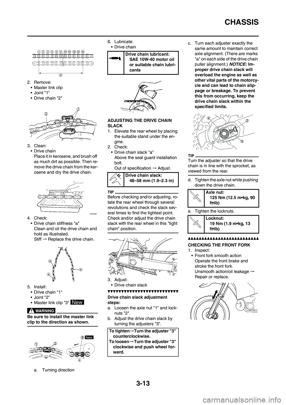
2. Remove:
• Master link clip
•Joint "1"
• Drive chain "2"
3. Clean:
• Drive chain
Place it in kerosene, and brush off
as much dirt as possible. Then re-
move the drive chain from the ker-
osene and dry the drive chain.
4. Check:
• Drive chain stiffness "a"
Clean and oil the drive chain and
hold as illustrated.
Stiff→Replace the drive chain.
5. Install:
• Drive chain "1"
•Joint "2"
• Master link clip "3"
Be sure to install the master link
clip to the direction as shown.
a. Turning direction6. Lubricate:
• Drive chain
ADJUSTING THE DRIVE CHAIN
SLACK
1. Elevate the rear wheel by placing
the suitable stand under the en-
gine.
2. Check:
• Drive chain slack "a"
Above the seal guard installation
bolt.
Out of specification→Adjust.
Before checking and/or adjusting, ro-
tate the rear wheel through several
revolutions and check the slack sev-
eral times to find the tightest point.
Check and/or adjust the drive chain
slack with the rear wheel in this "tight
chain" position.
3. Adjust:
• Drive chain slack
Drive chain slack adjustment
steps:
a. Loosen the axle nut "1" and lock-
nuts "2".
b. Adjust the drive chain slack by
turning the adjusters "3".c. Turn each adjuster exactly the
same amount to maintain correct
axle alignment. (There are marks
"a" on each side of the drive chain
puller alignment.) NOTICE: Im-
proper drive chain slack will
overload the engine as well as
other vital parts of the motorcy-
cle and can lead to chain slip-
page or breakage. To prevent
this from occurring, keep the
drive chain slack within the
specified limits.
Turn the adjuster so that the drive
chain is in line with the sprocket, as
viewed from the rear.
d. Tighten the axle nut while pushing
down the drive chain.
e. Tighten the locknuts.
CHECKING THE FRONT FORK
1. Inspect:
• Front fork smooth action
Operate the front brake and
stroke the front fork.
Unsmooth action/oil leakage→
Repair or replace.
Drive chain lubricant:
SAE 10W-40 motor oil
or suitable chain lubri-
cants
Drive chain slack:
48–58 mm (1.9–2.3 in)
To tighten→Turn the adjuster "3"
counterclockwise.
To loosen→Turn the adjuster "3"
clockwise and push wheel for-
ward.
Axle nut:
125 Nm (12.5 m•kg, 90
ft•lb)
Locknut:
19 Nm (1.9 m•kg, 13
ft•lb)
Page 55 of 166
3-14
CHASSIS
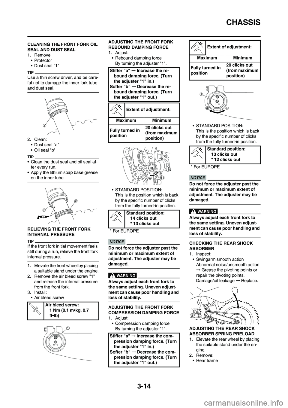
CLEANING THE FRONT FORK OIL
SEAL AND DUST SEAL
1. Remove:
•Protector
• Dust seal "1"
Use a thin screw driver, and be care-
ful not to damage the inner fork tube
and dust seal.
2. Clean:
• Dust seal "a"
• Oil seal "b"
• Clean the dust seal and oil seal af-
ter every run.
• Apply the lithium soap base grease
on the inner tube.
RELIEVING THE FRONT FORK
INTERNAL PRESSURE
If the front fork initial movement feels
stiff during a run, relieve the front fork
internal pressure.
1. Elevate the front wheel by placing
a suitable stand under the engine.
2. Remove the air bleed screw "1"
and release the internal pressure
from the front fork.
3. Install:
• Air bleed screwADJUSTING THE FRONT FORK
REBOUND DAMPING FORCE
1. Adjust:
• Rebound damping force
By turning the adjuster "1".
• STANDARD POSITION:
This is the position which is back
by the specific number of clicks
from the fully turned-in position.
Do not force the adjuster past the
minimum or maximum extent of
adjustment. The adjuster may be
damaged.
Always adjust each front fork to
the same setting. Uneven adjust-
ment can cause poor handling and
loss of stability.
ADJUSTING THE FRONT FORK
COMPRESSION DAMPING FORCE
1. Adjust:
• Compression damping force
By turning the adjuster "1".• STANDARD POSITION:
This is the position which is back
by the specific number of clicks
from the fully turned-in position.
Do not force the adjuster past the
minimum or maximum extent of
adjustment. The adjuster may be
damaged.
Always adjust each front fork to
the same setting. Uneven adjust-
ment can cause poor handling and
loss of stability.
CHECKING THE REAR SHOCK
ABSORBER
1. Inspect:
• Swingarm smooth action
Abnormal noise/unsmooth action
→Grease the pivoting points or
repair the pivoting points.
Damage/oil leakage→Replace.
ADJUSTING THE REAR SHOCK
ABSORBER SPRING PRELOAD
1. Elevate the rear wheel by placing
the suitable stand under the en-
gine.
2. Remove:
• Rear frame Air bleed screw:
1 Nm (0.1 m•kg, 0.7
ft•lb)
Stiffer "a" →Increase the re-
bound damping force. (Turn
the adjuster "1" in.)
Softer "b" →Decrease the re-
bound damping force. (Turn
the adjuster "1" out.)
Extent of adjustment:
Maximum Minimum
Fully turned in
position20 clicks out
(from maximum
position)
Standard position:
14 clicks out
* 13 clicks out
* For EUROPE
Stiffer "a" →Increase the com-
pression damping force. (Turn
the adjuster "1" in.)
Softer "b" →Decrease the com-
pression damping force. (Turn
the adjuster "1" out.)
Extent of adjustment:
Maximum Minimum
Fully turned in
position20 clicks out
(from maximum
position)
Standard position:
13 clicks out
* 12 clicks out
* For EUROPE
Page 76 of 166
4-16
CYLINDER HEAD, CYLINDER AND PISTON
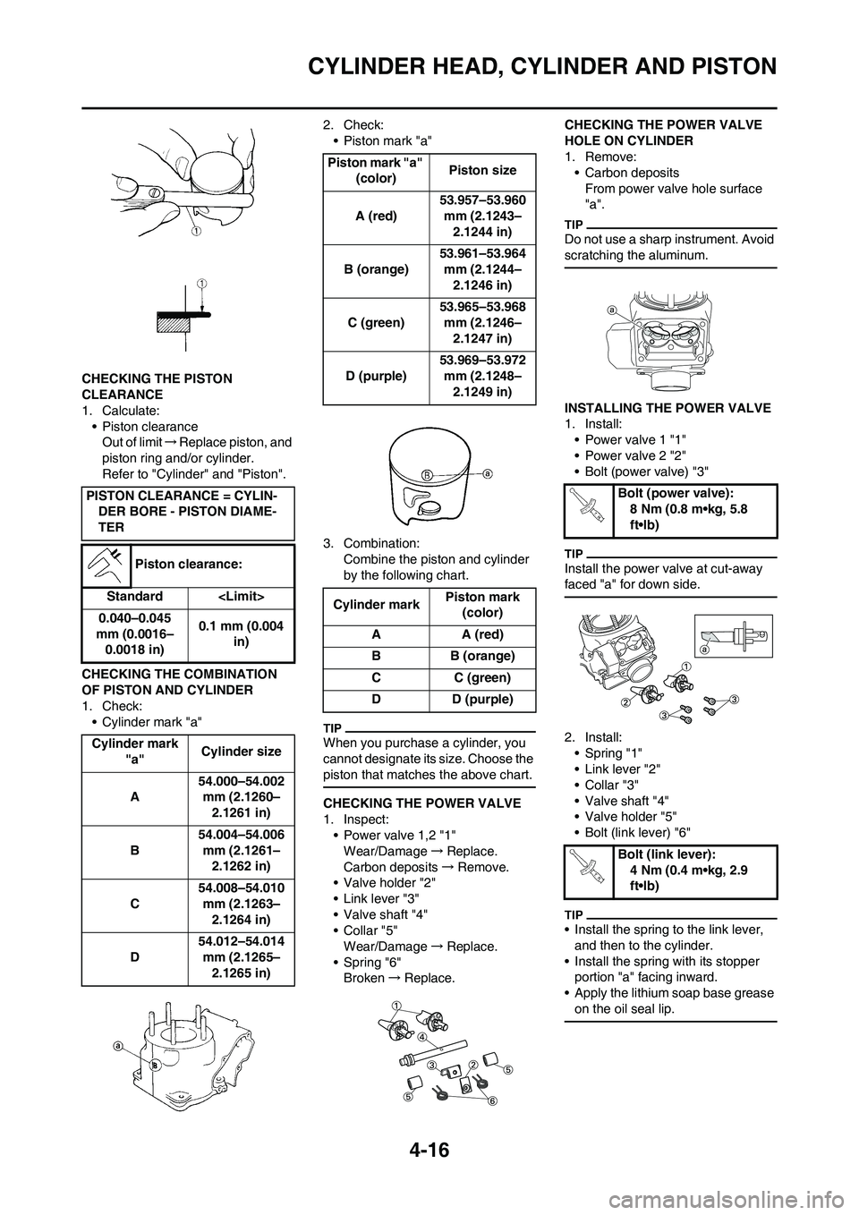
CHECKING THE PISTON
CLEARANCE
1. Calculate:
• Piston clearance
Out of limit→Replace piston, and
piston ring and/or cylinder.
Refer to "Cylinder" and "Piston".
CHECKING THE COMBINATION
OF PISTON AND CYLINDER
1. Check:
• Cylinder mark "a"2. Check:
• Piston mark "a"
3. Combination:
Combine the piston and cylinder
by the following chart.
When you purchase a cylinder, you
cannot designate its size. Choose the
piston that matches the above chart.
CHECKING THE POWER VALVE
1. Inspect:
• Power valve 1,2 "1"
Wear/Damage→Replace.
Carbon deposits→Remove.
• Valve holder "2"
• Link lever "3"
• Valve shaft "4"
• Collar "5"
Wear/Damage→Replace.
• Spring "6"
Broken→Replace.CHECKING THE POWER VALVE
HOLE ON CYLINDER
1. Remove:
• Carbon deposits
From power valve hole surface
"a".
Do not use a sharp instrument. Avoid
scratching the aluminum.
INSTALLING THE POWER VALVE
1. Install:
• Power valve 1 "1"
• Power valve 2 "2"
• Bolt (power valve) "3"
Install the power valve at cut-away
faced "a" for down side.
2. Install:
• Spring "1"
• Link lever "2"
•Collar "3"
• Valve shaft "4"
• Valve holder "5"
• Bolt (link lever) "6"
• Install the spring to the link lever,
and then to the cylinder.
• Install the spring with its stopper
portion "a" facing inward.
• Apply the lithium soap base grease
on the oil seal lip.
PISTON CLEARANCE = CYLIN-
DER BORE - PISTON DIAME-
TER
Piston clearance:
Standard
0.040–0.045
mm (0.0016–
0.0018 in)0.1 mm (0.004
in)
Cylinder mark
"a"Cylinder size
A54.000–54.002
mm (2.1260–
2.1261 in)
B54.004–54.006
mm (2.1261–
2.1262 in)
C54.008–54.010
mm (2.1263–
2.1264 in)
D54.012–54.014
mm (2.1265–
2.1265 in)
Piston mark "a"
(color)Piston size
A (red)53.957–53.960
mm (2.1243–
2.1244 in)
B (orange)53.961–53.964
mm (2.1244–
2.1246 in)
C (green)53.965–53.968
mm (2.1246–
2.1247 in)
D (purple)53.969–53.972
mm (2.1248–
2.1249 in)
Cylinder markPiston mark
(color)
AA (red)
BB (orange)
CC (green)
D D (purple)
Bolt (power valve):
8 Nm (0.8 m•kg, 5.8
ft•lb)
Bolt (link lever):
4 Nm (0.4 m•kg, 2.9
ft•lb)
Page 77 of 166
4-17
CYLINDER HEAD, CYLINDER AND PISTON
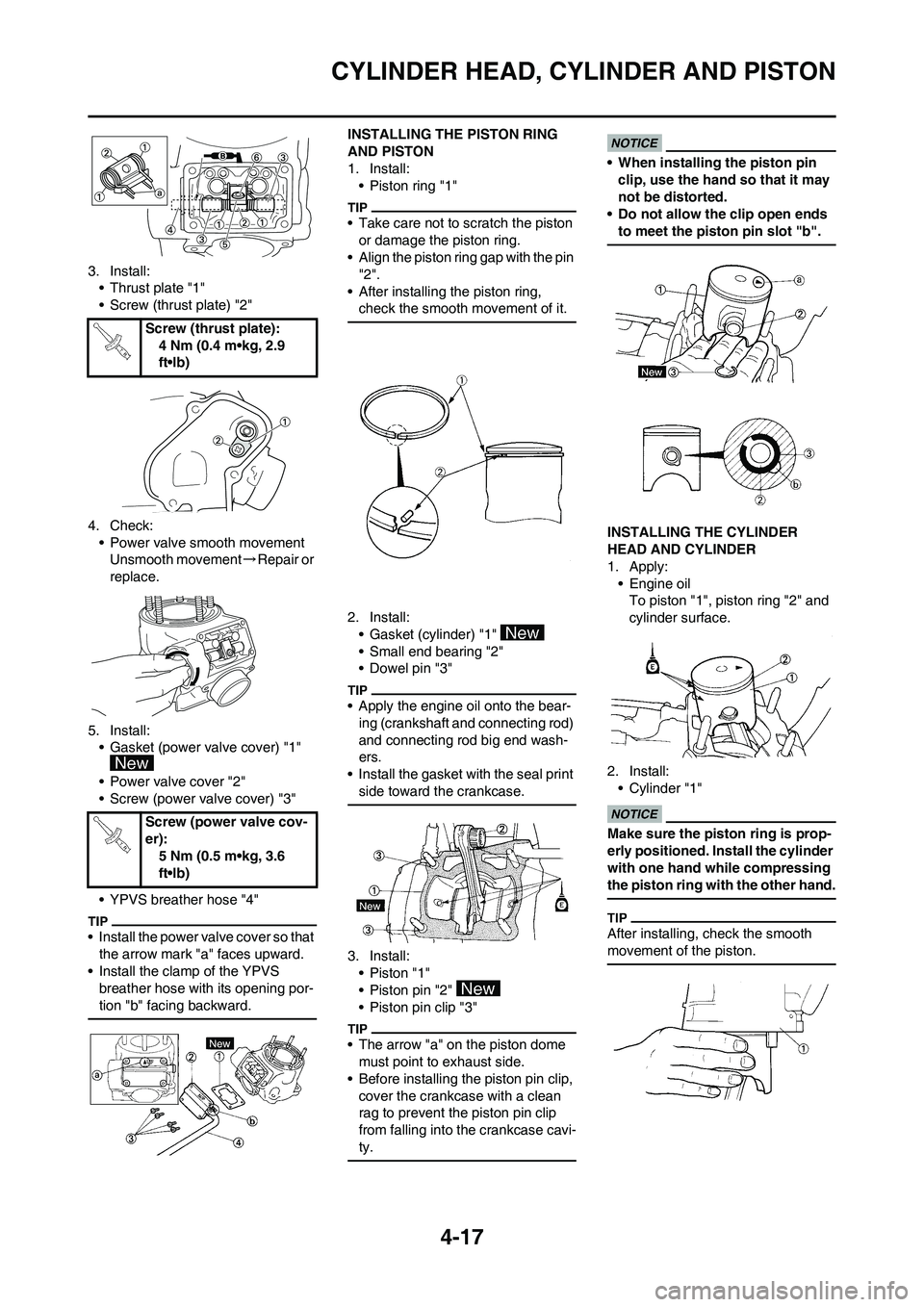
3. Install:
• Thrust plate "1"
• Screw (thrust plate) "2"
4. Check:
• Power valve smooth movement
Unsmooth movement→Repair or
replace.
5. Install:
• Gasket (power valve cover) "1"
• Power valve cover "2"
• Screw (power valve cover) "3"
• YPVS breather hose "4"
• Install the power valve cover so that
the arrow mark "a" faces upward.
• Install the clamp of the YPVS
breather hose with its opening por-
tion "b" facing backward.
INSTALLING THE PISTON RING
AND PISTON
1. Install:
• Piston ring "1"
• Take care not to scratch the piston
or damage the piston ring.
• Align the piston ring gap with the pin
"2".
• After installing the piston ring,
check the smooth movement of it.
2. Install:
• Gasket (cylinder) "1"
• Small end bearing "2"
• Dowel pin "3"
• Apply the engine oil onto the bear-
ing (crankshaft and connecting rod)
and connecting rod big end wash-
ers.
• Install the gasket with the seal print
side toward the crankcase.
3. Install:
•Piston "1"
• Piston pin "2"
• Piston pin clip "3"
• The arrow "a" on the piston dome
must point to exhaust side.
• Before installing the piston pin clip,
cover the crankcase with a clean
rag to prevent the piston pin clip
from falling into the crankcase cavi-
ty.
• When installing the piston pin
clip, use the hand so that it may
not be distorted.
• Do not allow the clip open ends
to meet the piston pin slot "b".
INSTALLING THE CYLINDER
HEAD AND CYLINDER
1. Apply:
• Engine oil
To piston "1", piston ring "2" and
cylinder surface.
2. Install:
• Cylinder "1"
Make sure the piston ring is prop-
erly positioned. Install the cylinder
with one hand while compressing
the piston ring with the other hand.
After installing, check the smooth
movement of the piston.
Screw (thrust plate):
4 Nm (0.4 m•kg, 2.9
ft•lb)
Screw (power valve cov-
er):
5 Nm (0.5 m•kg, 3.6
ft•lb)
Page 81 of 166
4-21
CLUTCH
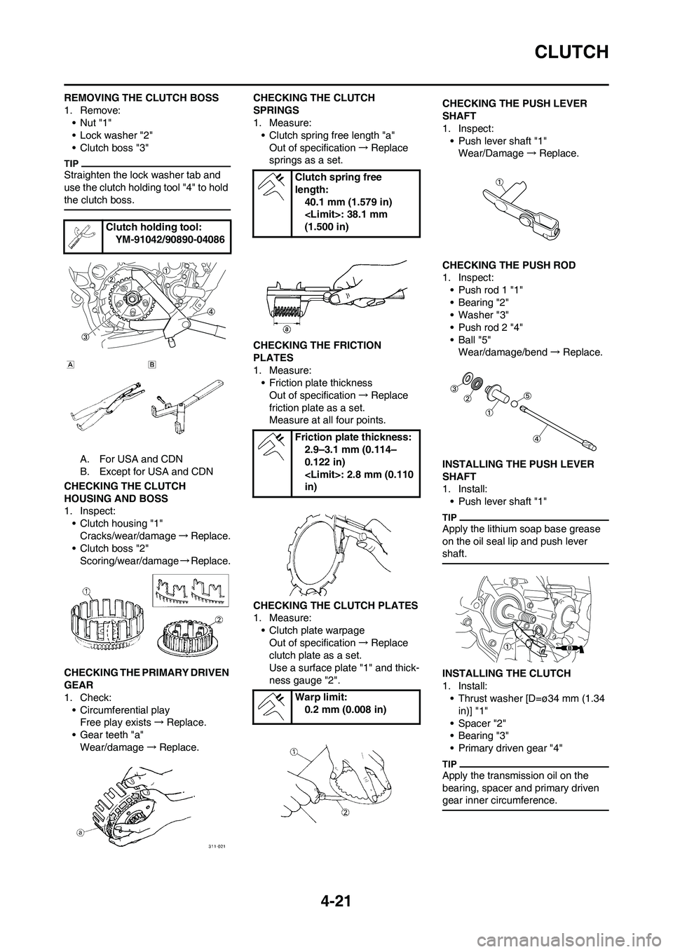
REMOVING THE CLUTCH BOSS
1. Remove:
•Nut "1"
• Lock washer "2"
• Clutch boss "3"
Straighten the lock washer tab and
use the clutch holding tool "4" to hold
the clutch boss.
A. For USA and CDN
B. Except for USA and CDN
CHECKING THE CLUTCH
HOUSING AND BOSS
1. Inspect:
• Clutch housing "1"
Cracks/wear/damage→Replace.
• Clutch boss "2"
Scoring/wear/damage→Replace.
CHECKING THE PRIMARY DRIVEN
GEAR
1. Check:
• Circumferential play
Free play exists→Replace.
• Gear teeth "a"
Wear/damage→Replace.CHECKING THE CLUTCH
SPRINGS
1. Measure:
• Clutch spring free length "a"
Out of specification→Replace
springs as a set.
CHECKING THE FRICTION
PLATES
1. Measure:
• Friction plate thickness
Out of specification→Replace
friction plate as a set.
Measure at all four points.
CHECKING THE CLUTCH PLATES
1. Measure:
• Clutch plate warpage
Out of specification→Replace
clutch plate as a set.
Use a surface plate "1" and thick-
ness gauge "2".CHECKING THE PUSH LEVER
SHAFT
1. Inspect:
• Push lever shaft "1"
Wear/Damage→Replace.
CHECKING THE PUSH ROD
1. Inspect:
• Push rod 1 "1"
• Bearing "2"
• Washer "3"
• Push rod 2 "4"
•Ball "5"
Wear/damage/bend→Replace.
INSTALLING THE PUSH LEVER
SHAFT
1. Install:
• Push lever shaft "1"
Apply the lithium soap base grease
on the oil seal lip and push lever
shaft.
INSTALLING THE CLUTCH
1. Install:
• Thrust washer [D=ø34 mm (1.34
in)] "1"
• Spacer "2"
• Bearing "3"
• Primary driven gear "4"
Apply the transmission oil on the
bearing, spacer and primary driven
gear inner circumference.
Clutch holding tool:
YM-91042/90890-04086
Clutch spring free
length:
40.1 mm (1.579 in)
(1.500 in)
Friction plate thickness:
2.9–3.1 mm (0.114–
0.122 in)
in)
Warp limit:
0.2 mm (0.008 in)