diagram YAMAHA YZ125LC 2013 Owners Manual
[x] Cancel search | Manufacturer: YAMAHA, Model Year: 2013, Model line: YZ125LC, Model: YAMAHA YZ125LC 2013Pages: 168, PDF Size: 8.19 MB
Page 8 of 168
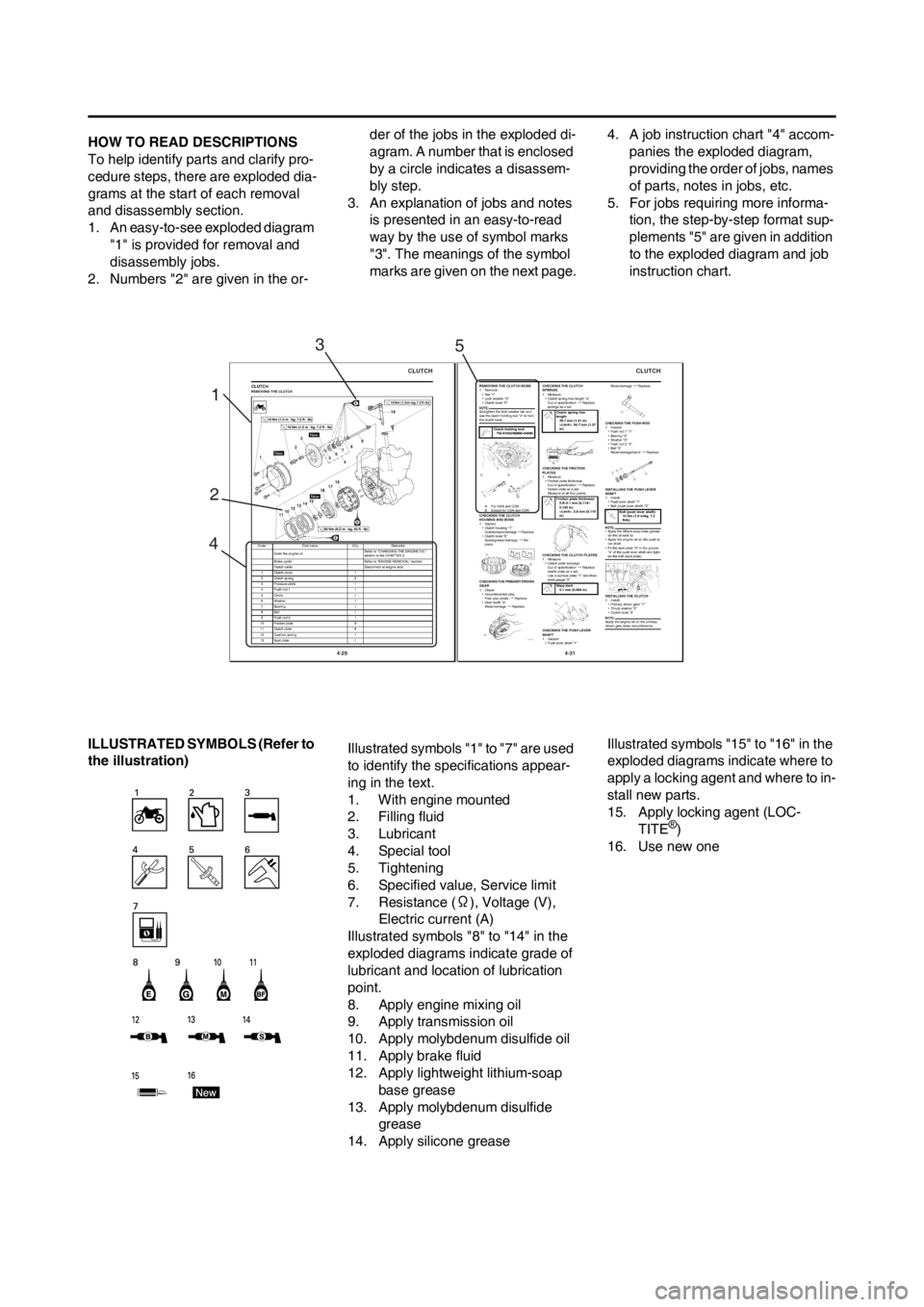
HOW TO READ DESCRIPTIONS
To help identify parts and clarify pro-
cedure steps, there are exploded dia-
grams at the start of each removal
and disassembly section.
1. An easy-to-see exploded diagram
"1" is provided for removal and
disassembly jobs.
2. Numbers "2" are given in the or-der of the jobs in the exploded di-
agram. A number that is enclosed
by a circle indicates a disassem-
bly step.
3. An explanation of jobs and notes
is presented in an easy-to-read
way by the use of symbol marks
"3". The meanings of the symbol
marks are given on the next page.4. A job instruction chart "4" accom-
panies the exploded diagram,
providing the order of jobs, names
of parts, notes in jobs, etc.
5. For jobs requiring more informa-
tion, the step-by-step format sup-
plements "5" are given in addition
to the exploded diagram and job
instruction chart.
ILLUSTRATED SYMBOLS (Refer to
the illustration)Illustrated symbols "1" to "7" are used
to identify the specifications appear-
ing in the text.
1. With engine mounted
2. Filling fluid
3. Lubricant
4. Special tool
5. Tightening
6. Specified value, Service limit
7. Resistance (Ω), Voltage (V),
Electric current (A)
Illustrated symbols "8" to "14" in the
exploded diagrams indicate grade of
lubricant and location of lubrication
point.
8. Apply engine mixing oil
9. Apply transmission oil
10. Apply molybdenum disulfide oil
11. Apply brake fluid
12. Apply lightweight lithium-soap
base grease
13. Apply molybdenum disulfide
grease
14. Apply silicone greaseIllustrated symbols "15" to "16" in the
exploded diagrams indicate where to
apply a locking agent and where to in-
stall new parts.
15. Apply locking agent (LOC-
TITE
®)
16. Use new one
1
23
45
Page 10 of 168

CONTENTS
CHAPTER 1GENERAL
INFORMATION
LOCATION OF IMPORTANT
LABELS............................ 1-1
DESCRIPTION ................. 1-5
CONSUMER
INFORMATION................. 1-6
INCLUDED PARTS .......... 1-6
IMPORTANT
INFORMATION................. 1-6
CHECKING OF
CONNECTION .................. 1-7
SPECIAL TOOLS ............. 1-8
CONTROL
FUNCTIONS ................... 1-11
STARTING AND
BREAK-IN ...................... 1-12
TORQUE-CHECK
POINTS........................... 1-13
CLEANING AND
STORAGE ...................... 1-14
CHAPTER 2
SPECIFICATIONS
GENERAL
SPECIFICATIONS ............ 2-1
MAINTENANCE
SPECIFICATIONS ............ 2-2
TIGHTENING TORQUES . 2-7
CABLE ROUTING
DIAGRAM ....................... 2-13
CHAPTER 3
REGULAR INSPEC-
TION AND AD-JUSTMENTS
MAINTENANCE
INTERVALS ...................... 3-1
PRE-OPERATION
INSPECTION AND
MAINTENANCE................ 3-5
ENGINE ............................ 3-6
CHASSIS .......................... 3-9
ELECTRICAL ................. 3-19
CHAPTER 4 ENGINE
SEAT, FUEL TANK AND
SIDE COVERS.................. 4-1
EXHAUST PIPE AND
SILENCER ........................ 4-3
RADIATOR ....................... 4-5
CARBURETOR AND
REED VALVE ................... 4-7
CYLINDER HEAD, CYLIN-
DER AND PISTON ......... 4-12
CLUTCH ......................... 4-19
KICK SHAFT AND
SHIFT SHAFT ................. 4-23
YPVS GOVERNOR......... 4-28
WATER PUMP................ 4-30
CDI MAGNETO............... 4-33
ENGINE REMOVAL ....... 4-35
CRANKCASE AND
CRANKSHAFT ............... 4-39
TRANSMISSION, SHIFT
CAM AND SHIFT FORK. 4-44
CHAPTER 5CHASSIS
FRONT WHEEL AND REAR
WHEEL .............................5-1
FRONT BRAKE AND
REAR BRAKE ..................5-6
FRONT FORK .................5-16
HANDLEBAR..................5-24
STEERING ......................5-29
SWINGARM ....................5-33
REAR SHOCK
ABSORBER ....................5-38
CHAPTER 6
ELECTRICAL
ELECTRICAL COMPO-
NENTS AND WIRING DIA-
GRAM ...............................6-2
IGNITION SYSTEM...........6-3
CHAPTER 7 TUNING
ENGINE.............................7-1
CHASSIS ..........................7-6
Page 38 of 168
2-13
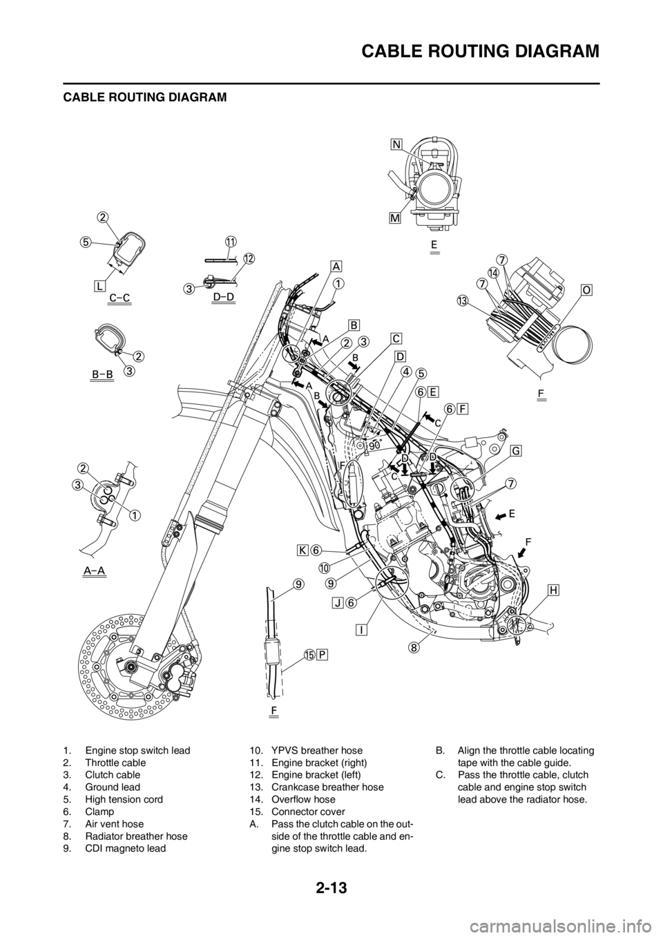
CABLE ROUTING DIAGRAM
CABLE ROUTING DIAGRAM
1. Engine stop switch lead
2. Throttle cable
3. Clutch cable
4. Ground lead
5. High tension cord
6. Clamp
7. Air vent hose
8. Radiator breather hose
9. CDI magneto lead10. YPVS breather hose
11. Engine bracket (right)
12. Engine bracket (left)
13. Crankcase breather hose
14. Overflow hose
15. Connector cover
A. Pass the clutch cable on the out-
side of the throttle cable and en-
gine stop switch lead.B. Align the throttle cable locating
tape with the cable guide.
C. Pass the throttle cable, clutch
cable and engine stop switch
lead above the radiator hose.
Page 39 of 168
2-14
CABLE ROUTING DIAGRAM
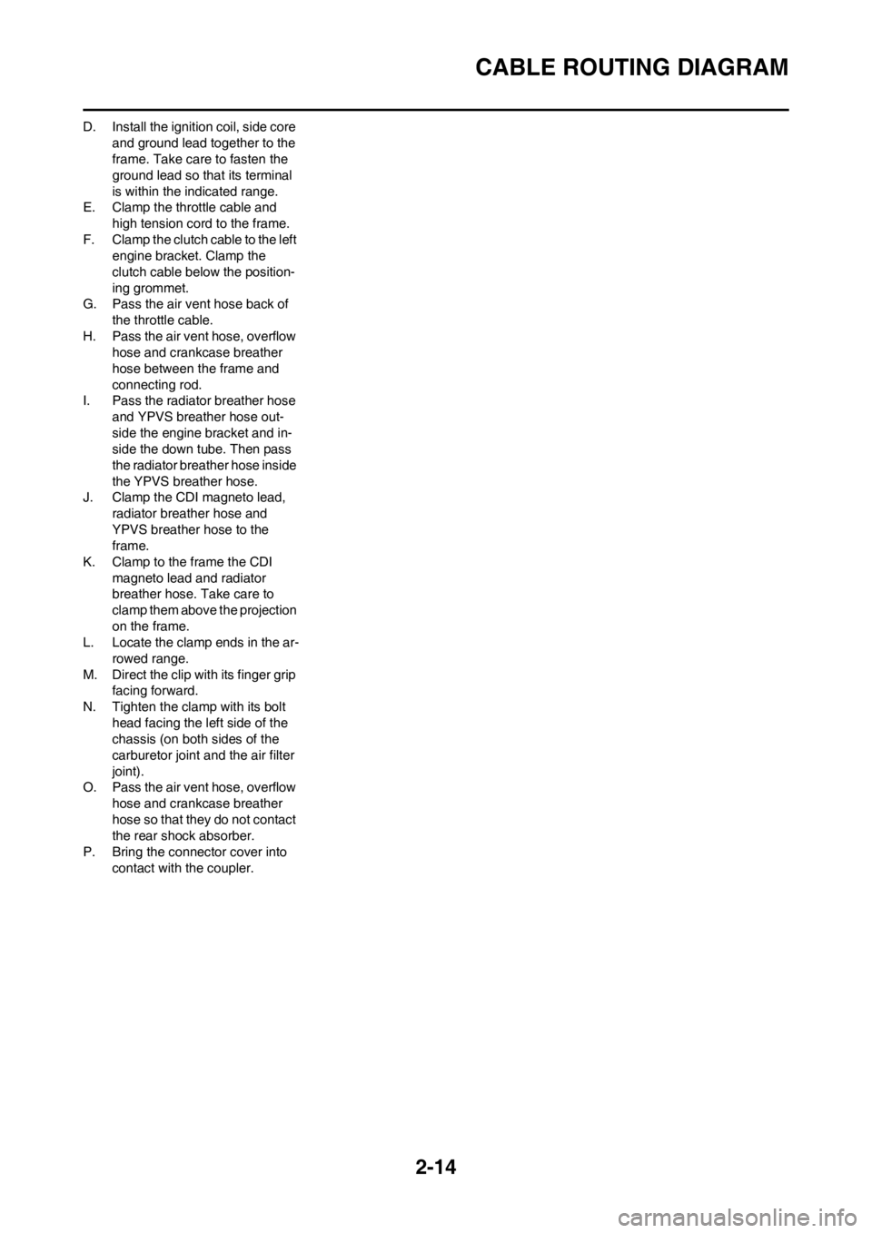
D. Install the ignition coil, side core
and ground lead together to the
frame. Take care to fasten the
ground lead so that its terminal
is within the indicated range.
E. Clamp the throttle cable and
high tension cord to the frame.
F. Clamp the clutch cable to the left
engine bracket. Clamp the
clutch cable below the position-
ing grommet.
G. Pass the air vent hose back of
the throttle cable.
H. Pass the air vent hose, overflow
hose and crankcase breather
hose between the frame and
connecting rod.
I. Pass the radiator breather hose
and YPVS breather hose out-
side the engine bracket and in-
side the down tube. Then pass
the radiator breather hose inside
the YPVS breather hose.
J. Clamp the CDI magneto lead,
radiator breather hose and
YPVS breather hose to the
frame.
K. Clamp to the frame the CDI
magneto lead and radiator
breather hose. Take care to
clamp them above the projection
on the frame.
L. Locate the clamp ends in the ar-
rowed range.
M. Direct the clip with its finger grip
facing forward.
N. Tighten the clamp with its bolt
head facing the left side of the
chassis (on both sides of the
carburetor joint and the air filter
joint).
O. Pass the air vent hose, overflow
hose and crankcase breather
hose so that they do not contact
the rear shock absorber.
P. Bring the connector cover into
contact with the coupler.
Page 40 of 168
2-15
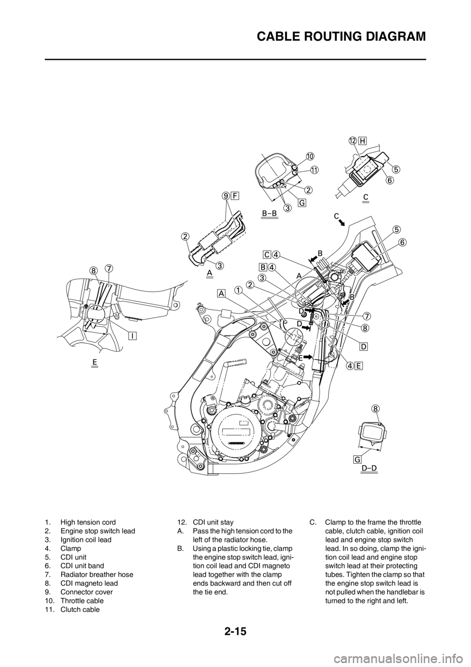
CABLE ROUTING DIAGRAM
1. High tension cord
2. Engine stop switch lead
3. Ignition coil lead
4. Clamp
5. CDI unit
6. CDI unit band
7. Radiator breather hose
8. CDI magneto lead
9. Connector cover
10. Throttle cable
11. Clutch cable12. CDI unit stay
A. Pass the high tension cord to the
left of the radiator hose.
B. Using a plastic locking tie, clamp
the engine stop switch lead, igni-
tion coil lead and CDI magneto
lead together with the clamp
ends backward and then cut off
the tie end.C. Clamp to the frame the throttle
cable, clutch cable, ignition coil
lead and engine stop switch
lead. In so doing, clamp the igni-
tion coil lead and engine stop
switch lead at their protecting
tubes. Tighten the clamp so that
the engine stop switch lead is
not pulled when the handlebar is
turned to the right and left.
Page 41 of 168
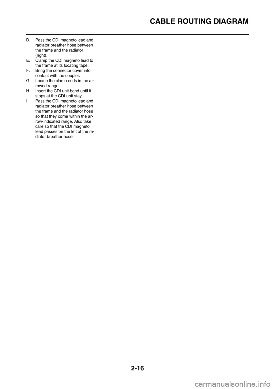
2-16
CABLE ROUTING DIAGRAM
D. Pass the CDI magneto lead and
radiator breather hose between
the frame and the radiator
(right).
E. Clamp the CDI magneto lead to
the frame at its locating tape.
F. Bring the connector cover into
contact with the coupler.
G. Locate the clamp ends in the ar-
rowed range.
H. Insert the CDI unit band until it
stops at the CDI unit stay.
I. Pass the CDI magneto lead and
radiator breather hose between
the frame and the radiator hose
so that they come within the ar-
row-indicated range. Also take
care so that the CDI magneto
lead passes on the left of the ra-
diator breather hose.
Page 42 of 168
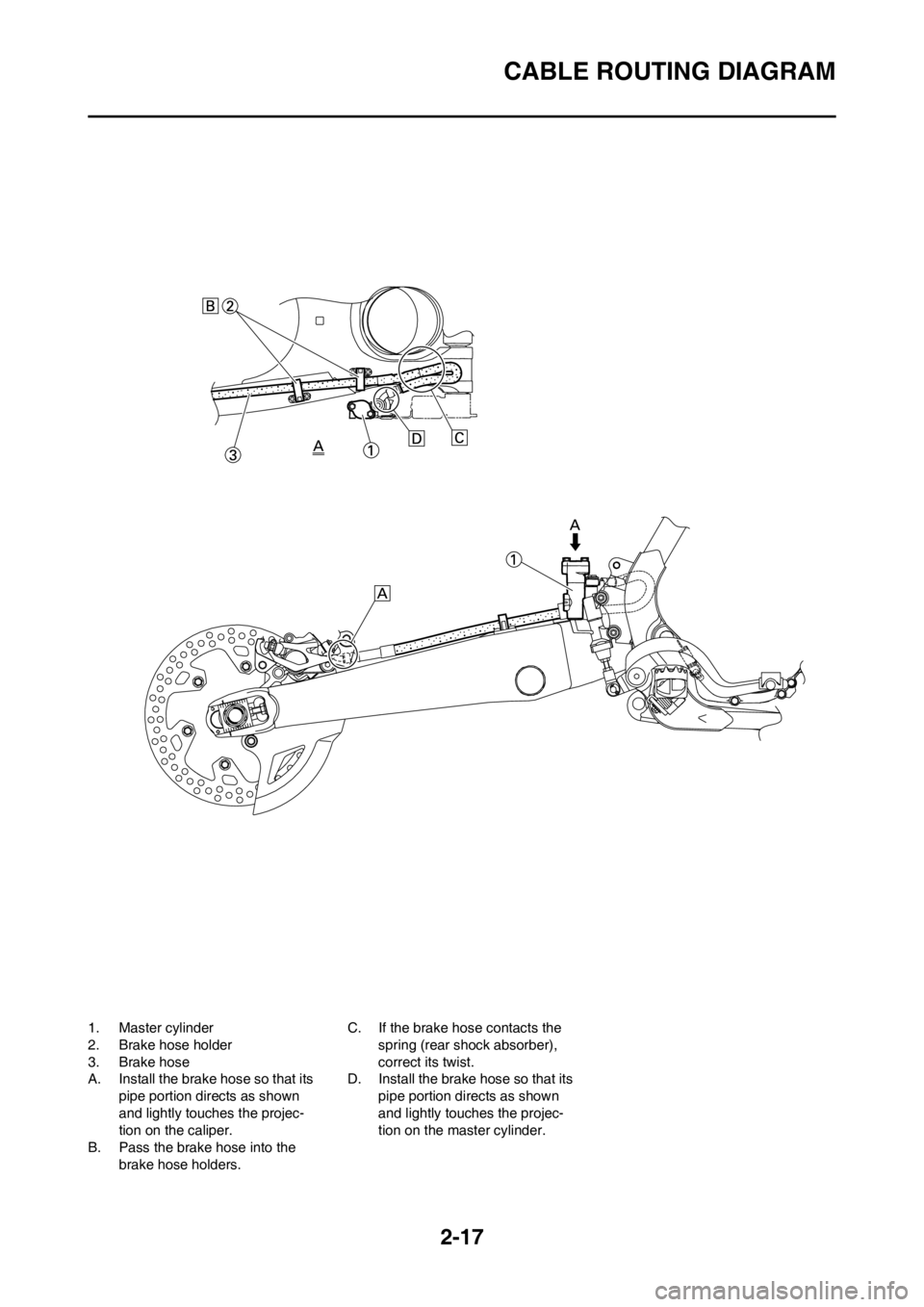
2-17
CABLE ROUTING DIAGRAM
1. Master cylinder
2. Brake hose holder
3. Brake hose
A. Install the brake hose so that its
pipe portion directs as shown
and lightly touches the projec-
tion on the caliper.
B. Pass the brake hose into the
brake hose holders.C. If the brake hose contacts the
spring (rear shock absorber),
correct its twist.
D. Install the brake hose so that its
pipe portion directs as shown
and lightly touches the projec-
tion on the master cylinder.
Page 43 of 168
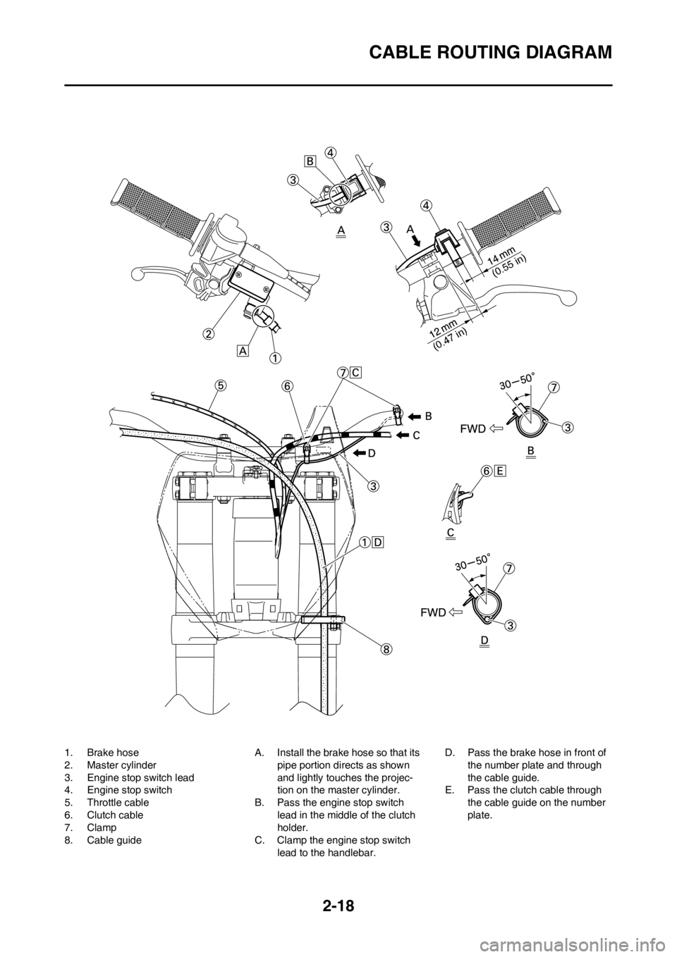
2-18
CABLE ROUTING DIAGRAM
1. Brake hose
2. Master cylinder
3. Engine stop switch lead
4. Engine stop switch
5. Throttle cable
6. Clutch cable
7. Clamp
8. Cable guideA. Install the brake hose so that its
pipe portion directs as shown
and lightly touches the projec-
tion on the master cylinder.
B. Pass the engine stop switch
lead in the middle of the clutch
holder.
C. Clamp the engine stop switch
lead to the handlebar.D. Pass the brake hose in front of
the number plate and through
the cable guide.
E. Pass the clutch cable through
the cable guide on the number
plate.
(0.55 in)
(0.47 in)
Page 152 of 168
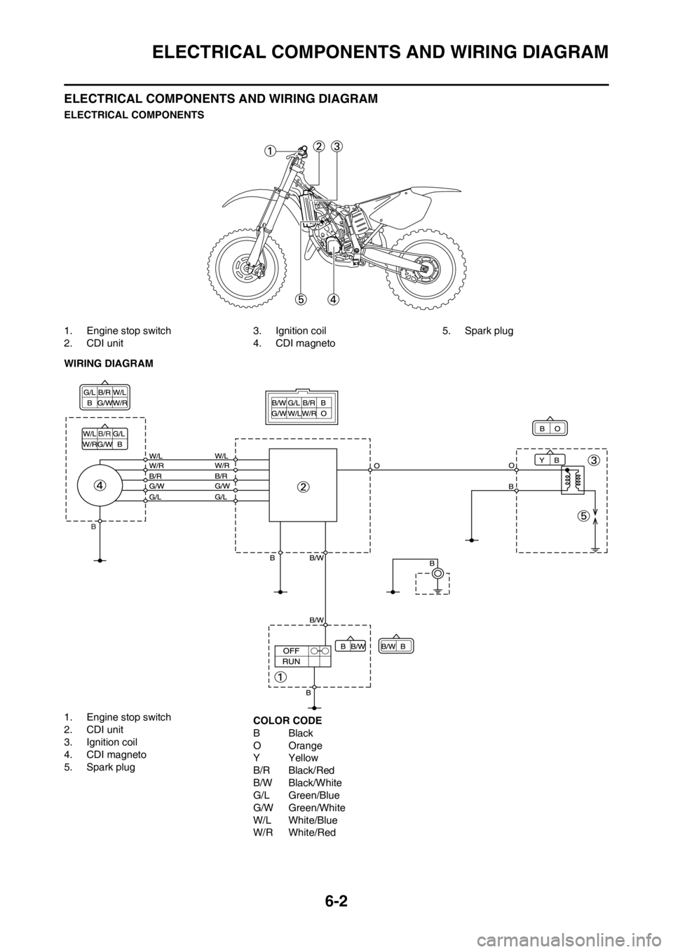
6-2
ELECTRICAL COMPONENTS AND WIRING DIAGRAM
ELECTRICAL COMPONENTS AND WIRING DIAGRAM
ELECTRICAL COMPONENTS
1. Engine stop switch
2. CDI unit3. Ignition coil
4. CDI magneto5. Spark plug
WIRING DIAGRAM
1. Engine stop switch
2. CDI unit
3. Ignition coil
4. CDI magneto
5. Spark plugCOLOR CODE
BBlack
O Orange
YYellow
B/R Black/Red
B/W Black/White
G/L Green/Blue
G/W Green/White
W/L White/Blue
W/R White/Red