length YAMAHA YZ125LC 2013 Owners Manual
[x] Cancel search | Manufacturer: YAMAHA, Model Year: 2013, Model line: YZ125LC, Model: YAMAHA YZ125LC 2013Pages: 168, PDF Size: 8.19 MB
Page 6 of 168
FOREWORD
INTRODUCTION
Congratulations on your purchase of
a Yamaha YZ series. This model is
the culmination of Yamaha's vast ex-
perience in the production of paceset-
ting racing machines. It represents
the highest grade of craftsmanship
and reliability that have made Yama-
ha a leader.
This manual explains operation, in-
spection, basic maintenance and tun-
ing of your machine. If you have any
questions about this manual or your
machine, please contact your Yama-
ha dealer.
Yamaha continually seeks advance-
ments in product design and quality.
Therefore, while this manual contains
the most current product information
available at the time of printing, there
may be minor discrepancies between
your machine and this manual. If you
have any questions concerning this
manual, please consult your Yamaha
dealer.
PLEASE READ THIS MANUAL
CAREFULLY AND COMPLETELY
BEFORE OPERATING THIS MA-
CHINE. DO NOT ATTEMPT TO OP-
ERATE THIS MACHINE UNTIL YOU
HAVE ATTAINED A SATISFACTO-
RY KNOWLEDGE OF ITS CON-
TROLS AND OPERATING
FEATURES AND UNTIL YOU HAVE
BEEN TRAINED IN SAFE AND
PROPER RIDING TECHNIQUES.
REGULAR INSPECTIONS AND
CAREFUL MAINTENANCE,
ALONG WITH GOOD RIDING
SKILLS, WILL ENSURE THAT YOU
SAFETY ENJOY THE CAPABILI-
TIES AND THE RELIABILITY OF
THIS MACHINE.
IMPORTANT MANUAL
INFORMATION
Particularly important information is
distinguished in this manual by the
following notations.
This is the safety alert symbol. It is
used to alert you to potential per-
sonal injury hazards. Obey all safe-
ty messages that follow this
symbol to avoid possible injury or
death.
A WARNING indicates a hazardous
situation which, if not avoided,
could result in death or serious in-
jury.
A NOTICE indicates special pre-
cautions that must be taken to
avoid damage to the vehicle or oth-
er property.
A TIP provides key information to
make procedures easier or clearer.
SAFETY INFORMATION
THIS MACHINE IS DESIGNED
STRICTLY FOR COMPETITION
USE, ONLY ON A CLOSED
COURSE. It is illegal for this machine
to be operated on any public street,
road, or highway. Off-road use on
public lands may also be illegal.
Please check local regulations before
riding.
• THIS MACHINE IS TO BE OPER-
ATED BY AN EXPERIENCED RID-
ER ONLY.
Do not attempt to operate this ma-
chine at maximum power until you
are totally familiar with its character-
istics.
• THIS MACHINE IS DESIGNED TO
BE RIDDEN BY THE OPERATOR
ONLY.
Do not carry passengers on this
machine.
• ALWAYS WEAR PROTECTIVE
APPAREL.
When operating this machine, al-
ways wear an approved helmet with
goggles or a face shield. Also wear
heavy boots, gloves, and protective
clothing. Always wear proper fitting
clothing that will not be caught in
any of the moving parts or controls
of the machine.• ALWAYS MAINTAIN YOUR MA-
CHINE IN PROPER WORKING
ORDER.
For safety and reliability, the ma-
chine must be properly maintained.
Always perform the pre-operation
checks indicated in this manual.
Correcting a mechanical problem
before you ride may prevent an ac-
cident.
• GASOLINE IS HIGHLY FLAMMA-
BLE.
Always turn off the engine while re-
fueling. Take care to not spill any
gasoline on the engine or exhaust
system. Never refuel in the vicinity
of an open flame, or while smoking.
• GASOLINE CAN CAUSE INJURY.
If you should swallow some gaso-
line, inhale excess gasoline vapors,
or allow any gasoline to get into
your eyes, contact a doctor immedi-
ately. If any gasoline spills onto
your skin or clothing, immediately
wash skin areas with soap and wa-
ter, and change your clothes.
• ONLY OPERATE THE MACHINE
IN AN AREA WITH ADEQUATE
VENTILATION.
Never start the engine or let it run
for any length of time in an enclosed
area. Exhaust fumes are poison-
ous. These fumes contain carbon
monoxide, which by itself is odor-
less and colorless. Carbon monox-
ide is a dangerous gas which can
cause unconsciousness or can be
lethal.
• PARK THE MACHINE CAREFUL-
LY; TURN OFF THE ENGINE.
Always turn off the engine if you are
going to leave the machine. Do not
park the machine on a slope or soft
ground as it may fall over.
• THE ENGINE, EXHAUST PIPE,
MUFFLER, AND OIL TANK WILL
BE VERY HOT AFTER THE EN-
GINE HAS BEEN RUN.
Be careful not to touch them or to
allow any clothing item to contact
them during inspection or repair.
• PROPERLY SECURE THE MA-
CHINE BEFORE TRANSPORTING
IT.
When transporting the machine in
another vehicle, always be sure it is
properly secured and in an upright
position and that the fuel cock is in
the "OFF" position. Otherwise, fuel
may leak out of the carburetor or
fuel tank.
Page 25 of 168
2-1
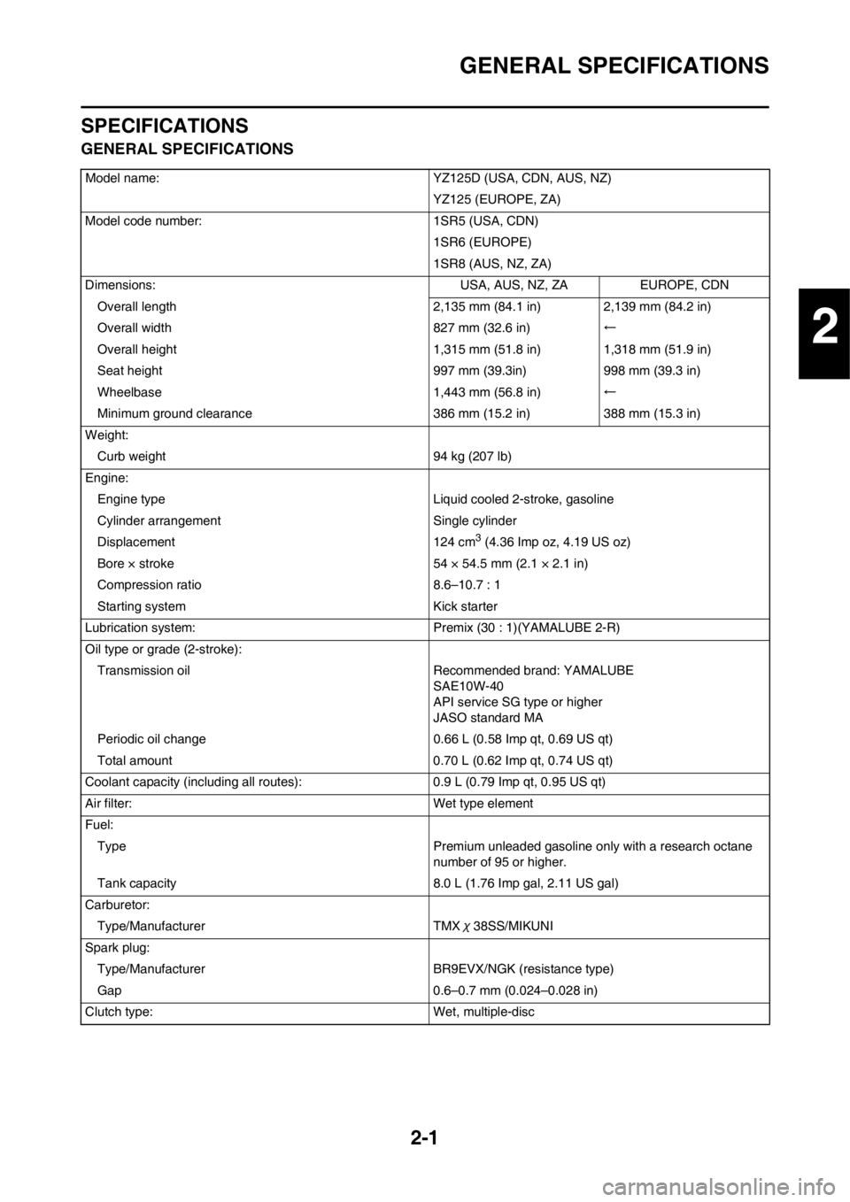
GENERAL SPECIFICATIONS
SPECIFICATIONS
GENERAL SPECIFICATIONS
Model name:YZ125D (USA, CDN, AUS, NZ)
YZ125 (EUROPE, ZA)
Model code number: 1SR5 (USA, CDN)
1SR6 (EUROPE)
1SR8 (AUS, NZ, ZA)
Dimensions: USA, AUS, NZ, ZAEUROPE, CDN
Overall length 2,135 mm (84.1 in) 2,139 mm (84.2 in)
Overall width 827 mm (32.6 in)←
Overall height 1,315 mm (51.8 in) 1,318 mm (51.9 in)
Seat height 997 mm (39.3in)998 mm (39.3 in)
Wheelbase 1,443 mm (56.8 in)←
Minimum ground clearance 386 mm (15.2 in)388 mm (15.3 in)
Weight: Curb weight 94 kg (207 lb)
Engine: Engine type Liquid cooled 2-stroke, gasoline
Cylinder arrangement Single cylinder
Displacement 124 cm
3 (4.36 Imp oz, 4.19 US oz)
Bore × stroke 54 × 54.5 mm (2.1 × 2.1 in)
Compression ratio 8.6–10.7 : 1
Starting system Kick starter
Lubrication system: Premix (30 : 1)(YAMALUBE 2-R)
Oil type or grade (2-stroke): Transmission oil Recommended brand: YAMALUBE SAE10W-40
API service SG type or higher
JASO standard MA
Periodic oil change 0.66 L (0.58 Imp qt, 0.69 US qt)
Total amount 0.70 L (0.62 Imp qt, 0.74 US qt)
Coolant capacity (including all routes): 0.9 L (0.79 Imp qt, 0.95 US qt)
Air filter: Wet type element
Fuel: Type Premium unleaded gasoline on ly with a research octane
number of 95 or higher.
Tank capacity 8.0 L (1.76 Imp gal, 2.11 US gal)
Carburetor: Type/Manufacturer TMX χ38SS/MIKUNI
Spark plug: Type/Manufacturer BR9EVX/NGK (resistance type)
Gap 0.6–0.7 mm (0.024–0.028 in)
Clutch type: Wet, multiple-disc
2
Page 28 of 168

2-4
MAINTENANCE SPECIFICATIONS
Clutch:
Friction plate thickness 2.9–3.1 mm (0.114–0.122 in) 2.8 mm (0.110
in)
Quantity 8 ----
Clutch plate thickness 1.5–1.7 mm (0.059–0.067 in) ----
Quantity 7 ----
Warp limit ---- 0.2 mm (0.008
in)
Clutch spring free length 40.1 mm (1.579 in) 38.1 mm
(1.500 in)
Quantity 5 ----
Clutch housing thrust clearance 0.15–0.26 mm (0.006–0.010 in) ----
Clutch housing radial clearance 0.01–0.04 mm (0.0006–0.0018 in) ----
Clutch release methodInner push, cam push ----
Transmission:
Main axle deflection limit ---- 0.01 mm
(0.0004 in)
Drive axle deflection limit ---- 0.01 mm
(0.0004 in)
Shifter:
Shifting type Cam drum and guide bar ----
Guide bar bending limit ---- 0.05 mm
(0.0020 in)
Kick starter type: Kick and mesh type ----
Kick clip friction force P=0.8–1.2 kg (1.8–2.6 lb) ----
Air filter oil grade (oiled filter): Foam-air-filter oil or equivalent oil ----
Carburetor: USA, CDN EUROPE AUS, NZ, ZA
Type/Manufacturer TMXχ38SS/
MIKUNI ←←
I.D. mark 1C37 51 1C36 41←----
Main jet (M.J.) #430←←----
Jet needle-clip position (J.N.) 6BFY43-74-3←←----
Cutaway (C.A.) 4.0←←----
Pilot jet (P.J.) #40 #45←----
Pilot air screw (P.A.S.) 2-1/4←←----
Valve seat size (V.S.) ø3.8 mm (0.15
in)←←----
Starter jet (G.S.) #80←←----
Fuel level (F.L.) 9.5–10.5 mm
(0.37–0.41 in)←←----
Reed valve:
Thickness 0.47 mm (0.019 in) ----
Valve stopper height 8.2–8.6 mm (0.323–0.339 in) ----
Valve bending limit ---- 0.2 mm (0.008
in) Item Standard Limit
Page 29 of 168

2-5
MAINTENANCE SPECIFICATIONS
CHASSISCooling:
Radiator core size:
Width 107.8 mm (4.24 in) ----
Height (left) 240 mm (9.45 in) ----
Height (right) 220 mm (8.66 in) ----
Thickness 32 mm (1.26 in) ----
Radiator cap opening pressure 95–125 kPa (0.95–1.25 kg/cm
2, 13.5–17.8 psi) ----
Radiator capacity (total) 0.56 L (0.49 Imp qt, 0.59 US qt) ----
Water pump:
Type Single-suction centrifugal pump ----
Item Standard Limit
Steering system:
Steering bearing typeTaper roller bearing ----
Front suspension: USA, CDN, ZA, AUS,
NZEUROPE
Front fork travel 300 mm (11.8 in)←----
Fork spring free length 454 mm (17.9 in)←449 mm (17.7
in)
Spring rate, STD K=4.1 N/mm (0.418
kg/mm, 23.4 lb/in)←----
Optional spring Yes←----
Oil capacity 524 cm
3 (18.4 Imp oz,
17.7 US oz) 526 cm3 (18.5 Imp oz,
17.8 US oz) ----
Oil grade Suspension oil "S1"←----
Inner tube outer diameter 48 mm (1.9 in)←----
Front fork top end 5 mm (0.2 in)←----
Rear suspension: USA, CDN, ZA, AUS,
NZEUROPE
Shock absorber travel 131.5 mm (5.18 in)←----
Spring free length Approx. 265 mm (10.43
in)←----
Fitting length*----
I.D. mark (Red/1) 258 mm (10.16 in) 252 mm (9.92 in) ----
I.D. mark (Red/2) 264 mm (10.39 in) 258 mm (10.16 in) ----
I.D. mark (Red/3) 255.5 mm (10.06 in) 249.5 mm (9.82 in) ----
Preload length
in)←----
Spring rate, STD K=46.0 N/mm (4.70
kg/mm, 263.2 lb/in)←----
Optional spring Yes←----
Enclosed gas pressure 1,000 kPa (10 kg/cm
2,
142 psi) ←----
* Spring specification varies according to the differ-
ence in the production lot.Item Standard Limit
Page 30 of 168

2-6
MAINTENANCE SPECIFICATIONS
Swingarm:
Swingarm free play limit
End ---- 1.0 mm (0.04
in)
Side clearance ---- 0.2–0.9 mm
(0.008–0.035
in)
Wheel:
Front wheel type Spoke wheel ----
Rear wheel typeSpoke wheel ----
Front rim size/material 21 × 1.60/Aluminum ----
Rear rim size/material 19 × 1.85/Aluminum ----
Rim runout limit:
Radial ---- 2.0 mm (0.08
in)
Lateral ---- 2.0 mm (0.08
in)
Drive chain:
Type/manufacturer DID520DMA2 SDH G&B/DAIDO ----
Number of links 111 links + joint ----
Chain slack 48–58 mm (1.9–2.3 in) ----
Chain length (15 links) ---- 242.9 mm
(9.563 in)
Front disc brake:
Disc outside dia.×Thickness 250 × 3.0 mm (9.84 × 0.12 in) 250 × 2.5 mm
(9.84 × 0.10 in)
Pad thickness 4.4 mm (0.17 in) 1.0 mm (0.04
in)
Master cylinder inside dia. 9.52 mm (0.375 in) ----
Caliper cylinder inside dia. 22.65 mm (0.892 in) × 2 ----
Brake fluid type DOT #4 ----
Rear disc brake:
Disc outside dia.×Thickness 245 × 4.0 mm (9.65 × 0.16 in) 245 × 3.5 mm
(9.65 × 0.14 in)
Deflection limit ---- 0.15 mm
(0.006 in)
Pad thickness 6.4 mm (0.25 in) 1.0 mm (0.04
in)
Master cylinder inside dia. 11.0 mm (0.433 in) ----
Caliper cylinder inside dia. 25.4 mm (1.000 in) × 1 ----
Brake fluid type DOT #4 ----
Brake lever and brake pedal:
Brake lever position 95 mm (3.74 in) ----
Brake pedal height (vertical height above footrest
top)0 mm (0 in) ----
Clutch lever free play (lever end) 8–13 mm (0.31–0.51 in) ----
Throttle grip free play3–5 mm (0.12–0.20 in) ---- Item Standard Limit
Page 36 of 168

2-12
TIGHTENING TORQUES
GENERAL TORQUE
SPECIFICATIONS
This chart specifies torque for stan-
dard fasteners with standard I.S.O.
pitch threads. Torque specifications
for special components or assem-
blies are included in the applicable
sections of this book. To avoid warp-
age, tighten multi-fastener assem-
blies in a crisscross fashion, in
progressive stages, until full torque is
reached. Unless otherwise specified,
torque specifications call for clean,
dry threads. Components should be
at room temperature.A. Distance between flats
B. Outside thread diameter
DEFINITION OF UNITS
A
(Nut)B
(Bolt
)TORQUE SPECIFI-
CATION
Nm m•kg ft•lb
10
mm6 mm 6 0.6 4.3
12
mm8 mm 15 1.5 11
14
mm10
mm30 3.0 22
17
mm12
mm55 5.5 40
19
mm14
mm85 8.5 61
22
mm16
mm130 13 94
Unit Read Definition Measure
mm
millimeter 10-3 meter Length
cmcentimeter 10-2 meter Length
kgkilogram 103 gram Weight
NNewton 1 kg × m/sec2Force
NmNewton meter N × m Torque
m•kgMeter kilogram m × kg Torque
PaPascal N/m2Pressure
N/mmNewton per millimeter N/mm Spring rate
LLiter — Volume or capacity
cm3Cubic centimeter — Volume or capacity
r/minRevolution per minute — Engine speed
Page 55 of 168
3-12
CHASSIS
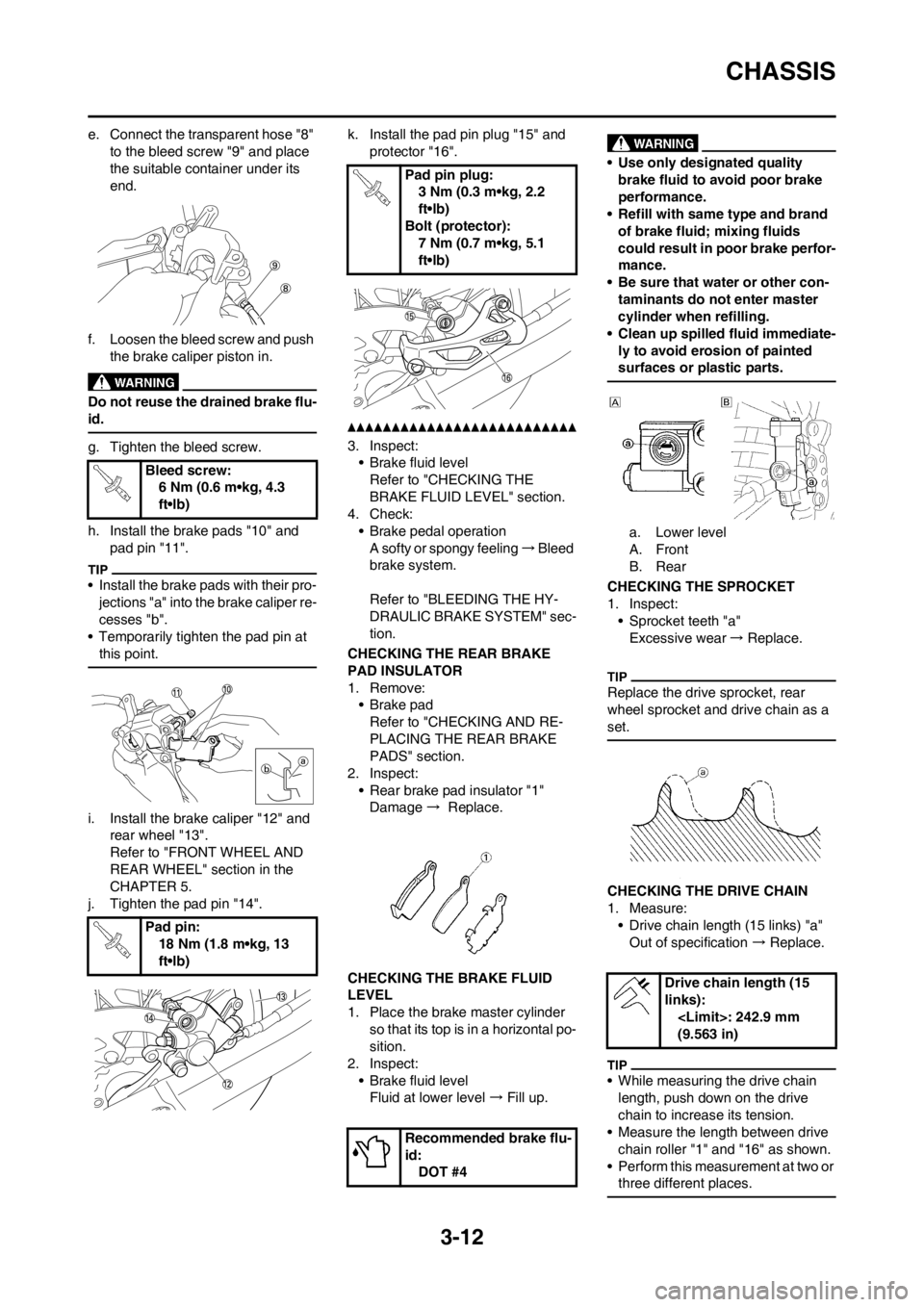
e. Connect the transparent hose "8"
to the bleed screw "9" and place
the suitable container under its
end.
f. Loosen the bleed screw and push
the brake caliper piston in.
Do not reuse the drained brake flu-
id.
g. Tighten the bleed screw.
h. Install the brake pads "10" and
pad pin "11".
• Install the brake pads with their pro-
jections "a" into the brake caliper re-
cesses "b".
• Temporarily tighten the pad pin at
this point.
i. Install the brake caliper "12" and
rear wheel "13".
Refer to "FRONT WHEEL AND
REAR WHEEL" section in the
CHAPTER 5.
j. Tighten the pad pin "14".k. Install the pad pin plug "15" and
protector "16".
3. Inspect:
• Brake fluid level
Refer to "CHECKING THE
BRAKE FLUID LEVEL" section.
4. Check:
• Brake pedal operation
A softy or spongy feeling → Bleed
brake system.
Refer to "BLEEDING THE HY-
DRAULIC BRAKE SYSTEM" sec-
tion.
CHECKING THE REAR BRAKE
PAD INSULATOR
1. Remove:
•Brake pad
Refer to "CHECKING AND RE-
PLACING THE REAR BRAKE
PADS" section.
2. Inspect:
• Rear brake pad insulator "1"
Damage → Replace.
CHECKING THE BRAKE FLUID
LEVEL
1. Place the brake master cylinder
so that its top is in a horizontal po-
sition.
2. Inspect:
• Brake fluid level
Fluid at lower level → Fill up.
• Use only designated quality
brake fluid to avoid poor brake
performance.
• Refill with same type and brand
of brake fluid; mixing fluids
could result in poor brake perfor-
mance.
• Be sure that water or other con-
taminants do not enter master
cylinder when refilling.
• Clean up spilled fluid immediate-
ly to avoid erosion of painted
surfaces or plastic parts.
a. Lower level
A. Front
B. Rear
CHECKING THE SPROCKET
1. Inspect:
• Sprocket teeth "a"
Excessive wear→ Replace.
Replace the drive sprocket, rear
wheel sprocket and drive chain as a
set.
CHECKING THE DRIVE CHAIN
1. Measure:
• Drive chain length (15 links) "a"
Out of specification → Replace.
• While measuring the drive chain
length, push down on the drive
chain to increase its tension.
• Measure the length between drive
chain roller "1" and "16" as shown.
• Perform this measurement at two or
three different places.
Bleed screw:
6 Nm (0.6 m•kg, 4.3
ft•lb)
Pad pin:
18 Nm (1.8 m•kg, 13
ft•lb)
Pad pin plug:
3 Nm (0.3 m•kg, 2.2
ft•lb)
Bolt (protector):
7 Nm (0.7 m•kg, 5.1
ft•lb)
Recommended brake flu-
id:
DOT #4
Drive chain length (15
links):
(9.563 in)
Page 58 of 168
3-15
CHASSIS
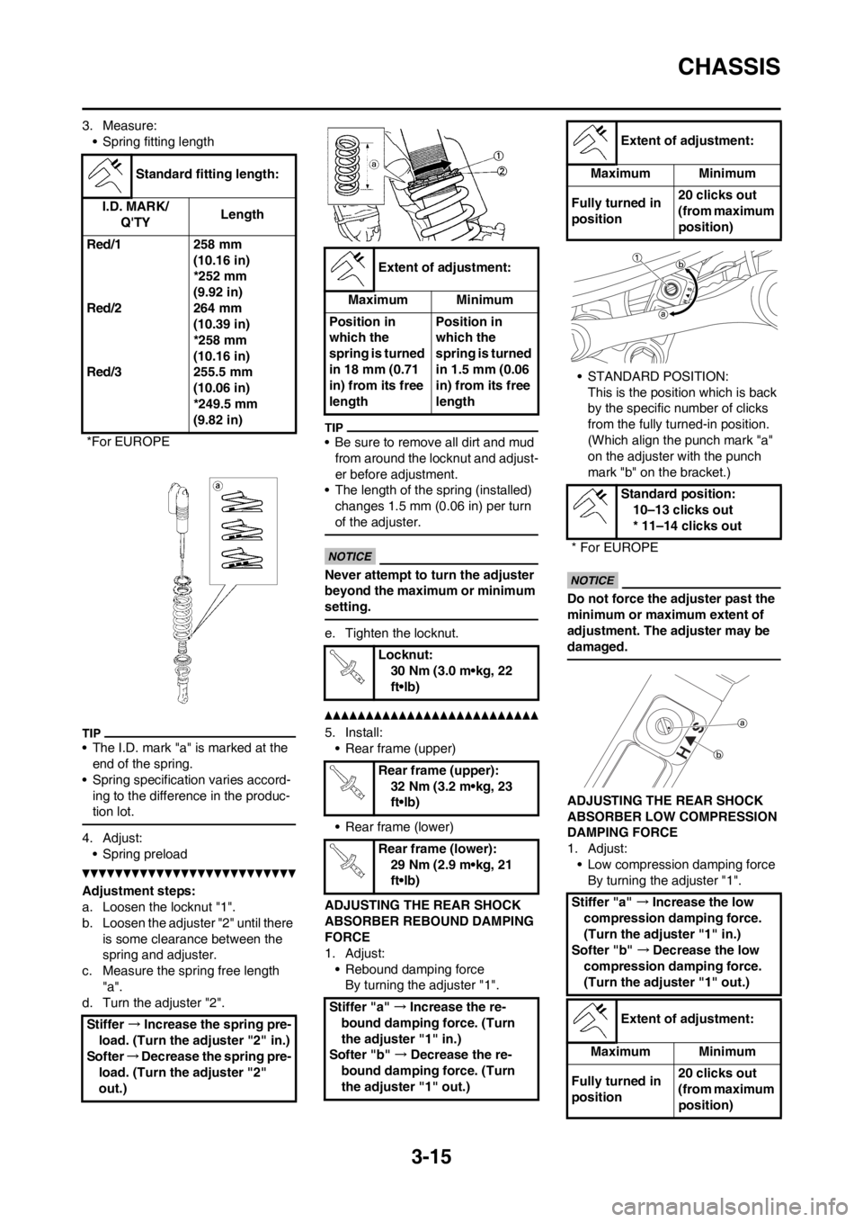
3. Measure:
• Spring fitting length
• The I.D. mark "a" is marked at the
end of the spring.
• Spring specification varies accord-
ing to the difference in the produc-
tion lot.
4. Adjust:
• Spring preload
Adjustment steps:
a. Loosen the locknut "1".
b. Loosen the adjuster "2" until there
is some clearance between the
spring and adjuster.
c. Measure the spring free length
"a".
d. Turn the adjuster "2".
• Be sure to remove all dirt and mud
from around the locknut and adjust-
er before adjustment.
• The length of the spring (installed)
changes 1.5 mm (0.06 in) per turn
of the adjuster.
Never attempt to turn the adjuster
beyond the maximum or minimum
setting.
e. Tighten the locknut.
5. Install:
• Rear frame (upper)
• Rear frame (lower)
ADJUSTING THE REAR SHOCK
ABSORBER REBOUND DAMPING
FORCE
1. Adjust:
• Rebound damping force
By turning the adjuster "1".• STANDARD POSITION:
This is the position which is back
by the specific number of clicks
from the fully turned-in position.
(Which align the punch mark "a"
on the adjuster with the punch
mark "b" on the bracket.)
Do not force the adjuster past the
minimum or maximum extent of
adjustment. The adjuster may be
damaged.
ADJUSTING THE REAR SHOCK
ABSORBER LOW COMPRESSION
DAMPING FORCE
1. Adjust:
• Low compression damping force
By turning the adjuster "1". Standard fitting length:
I.D. MARK/
Q'TYLength
Red/1
Red/2
Red/3258 mm
(10.16 in)
*252 mm
(9.92 in)
264 mm
(10.39 in)
*258 mm
(10.16 in)
255.5 mm
(10.06 in)
*249.5 mm
(9.82 in)
*For EUROPE
Stiffer →Increase the spring pre-
load. (Turn the adjuster "2" in.)
Softer→Decrease the spring pre-
load. (Turn the adjuster "2"
out.)
Extent of adjustment:
Maximum Minimum
Position in
which the
spring is turned
in 18 mm (0.71
in) from its free
lengthPosition in
which the
spring is turned
in 1.5 mm (0.06
in) from its free
length
Locknut:
30 Nm (3.0 m•kg, 22
ft•lb)
Rear frame (upper):
32 Nm (3.2 m•kg, 23
ft•lb)
Rear frame (lower):
29 Nm (2.9 m•kg, 21
ft•lb)
Stiffer "a" →Increase the re-
bound damping force. (Turn
the adjuster "1" in.)
Softer "b" →Decrease the re-
bound damping force. (Turn
the adjuster "1" out.)
Extent of adjustment:
Maximum Minimum
Fully turned in
position20 clicks out
(from maximum
position)
Standard position:
10–13 clicks out
* 11–14 clicks out
* For EUROPE
Stiffer "a" →Increase the low
compression damping force.
(Turn the adjuster "1" in.)
Softer "b" →Decrease the low
compression damping force.
(Turn the adjuster "1" out.)
Extent of adjustment:
Maximum Minimum
Fully turned in
position20 clicks out
(from maximum
position)
Page 83 of 168
4-21
CLUTCH
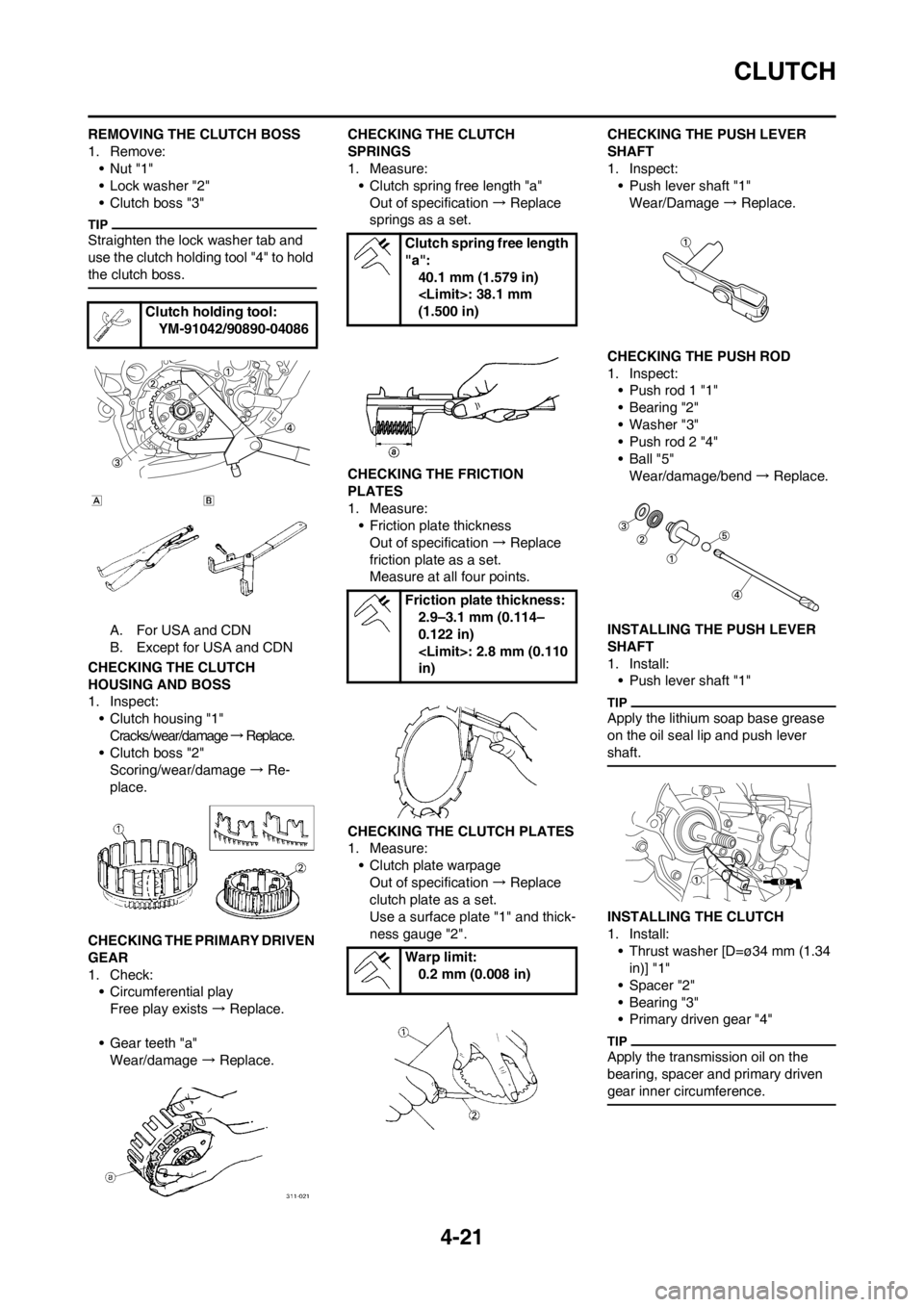
REMOVING THE CLUTCH BOSS
1. Remove:
•Nut "1"
• Lock washer "2"
• Clutch boss "3"
Straighten the lock washer tab and
use the clutch holding tool "4" to hold
the clutch boss.
A. For USA and CDN
B. Except for USA and CDN
CHECKING THE CLUTCH
HOUSING AND BOSS
1. Inspect:
• Clutch housing "1"
Cracks/wear/damage → R e p l a c e .
• Clutch boss "2"
Scoring/wear/damage → Re-
place.
CHECKING THE PRIMARY DRIVEN
GEAR
1. Check:
• Circumferential play
Free play exists → Replace.
• Gear teeth "a"
Wear/damage → Replace. CHECKING THE CLUTCH
SPRINGS
1. Measure:
• Clutch spring free length "a"
Out of specification → Replace
springs as a set.
CHECKING THE FRICTION
PLATES
1. Measure:
• Friction plate thickness
Out of specification → Replace
friction plate as a set.
Measure at all four points.
CHECKING THE CLUTCH PLATES
1. Measure:
• Clutch plate warpage
Out of specification → Replace
clutch plate as a set.
Use a surface plate "1" and thick-
ness gauge "2".CHECKING THE PUSH LEVER
SHAFT
1. Inspect:
• Push lever shaft "1"
Wear/Damage → Replace.
CHECKING THE PUSH ROD
1. Inspect:
• Push rod 1 "1"
• Bearing "2"
• Washer "3"
• Push rod 2 "4"
•Ball "5"
Wear/damage/bend → Replace.
INSTALLING THE PUSH LEVER
SHAFT
1. Install:
• Push lever shaft "1"
Apply the lithium soap base grease
on the oil seal lip and push lever
shaft.
INSTALLING THE CLUTCH
1. Install:
• Thrust washer [D=ø34 mm (1.34
in)] "1"
• Spacer "2"
• Bearing "3"
• Primary driven gear "4"
Apply the transmission oil on the
bearing, spacer and primary driven
gear inner circumference.
Clutch holding tool:
YM-91042/90890-04086
Clutch spring free length
"a":
40.1 mm (1.579 in)
(1.500 in)
Friction plate thickness:
2.9–3.1 mm (0.114–
0.122 in)
in)
Warp limit:
0.2 mm (0.008 in)
Page 127 of 168
5-19
FRONT FORK
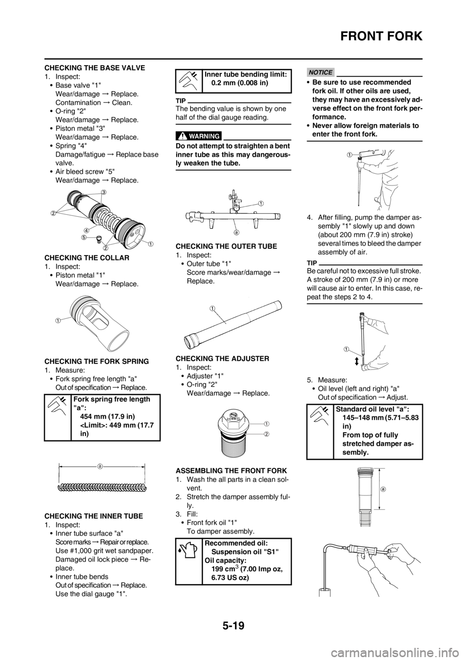
CHECKING THE BASE VALVE
1. Inspect:
• Base valve "1"
Wear/damage → Replace.
Contamination → Clean.
• O-ring "2"
Wear/damage → Replace.
• Piston metal "3"
Wear/damage → Replace.
• Spring "4"
Damage/fatigue → Replace base
valve.
• Air bleed screw "5"
Wear/damage → Replace.
CHECKING THE COLLAR
1. Inspect:
• Piston metal "1"
Wear/damage → Replace.
CHECKING THE FORK SPRING
1. Measure:
• Fork spring free length "a"
Out of specification → R e p l a c e .
CHECKING THE INNER TUBE
1. Inspect:
• Inner tube surface "a"
Score marks → Repair or replace.
Use #1,000 grit wet sandpaper.
Damaged oil lock piece → Re-
place.
• Inner tube bends
Out of specification → R e p l a c e .
Use the dial gauge "1".
The bending value is shown by one
half of the dial gauge reading.
Do not attempt to straighten a bent
inner tube as this may dangerous-
ly weaken the tube.
CHECKING THE OUTER TUBE
1. Inspect:
• Outer tube "1"
Score marks/wear/damage →
Replace.
CHECKING THE ADJUSTER
1. Inspect:
•Adjuster "1"
• O-ring "2"
Wear/damage → Replace.
ASSEMBLING THE FRONT FORK
1. Wash the all parts in a clean sol-
vent.
2. Stretch the damper assembly ful-
ly.
3. Fill:
• Front fork oil "1"
To damper assembly.
• Be sure to use recommended
fork oil. If other oils are used,
they may have an excessively ad-
verse effect on the front fork per-
formance.
• Never allow foreign materials to
enter the front fork.
4. After filling, pump the damper as-
sembly "1" slowly up and down
(about 200 mm (7.9 in) stroke)
several times to bleed the damper
assembly of air.
Be careful not to excessive full stroke.
A stroke of 200 mm (7.9 in) or more
will cause air to enter. In this case, re-
peat the steps 2 to 4.
5. Measure:
• Oil level (left and right) "a"
Out of specification → A d j u s t .
Fork spring free length
"a":
454 mm (17.9 in)
in)
Inner tube bending limit:
0.2 mm (0.008 in)
Recommended oil:
Suspension oil "S1"
Oil capacity:
199 cm
3 (7.00 Imp oz,
6.73 US oz)
Standard oil level "a":
145–148 mm (5.71–5.83
in)
From top of fully
stretched damper as-
sembly.