oil YAMAHA YZ250F 2006 Manuale duso (in Italian)
[x] Cancel search | Manufacturer: YAMAHA, Model Year: 2006, Model line: YZ250F, Model: YAMAHA YZ250F 2006Pages: 674, PDF Dimensioni: 21.07 MB
Page 76 of 674
SPEC
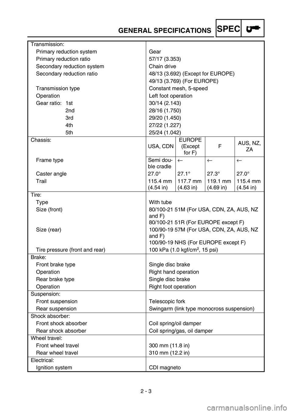
2 - 3 Transmission:
Primary reduction system Gear
Primary reduction ratio 57/17 (3.353)
Secondary reduction system Chain drive
Secondary reduction ratio 48/13 (3.692) (Except for EUROPE)
49/13 (3.769) (For EUROPE)
Transmission type Constant mesh, 5-speed
Operation Left foot operation
Gear ratio: 1st 30/14 (2.143)
2nd 28/16 (1.750)
3rd 29/20 (1.450)
4th 27/22 (1.227)
5th 25/24 (1.042)
Chassis:
USA, CDNEUROPE
(Except
for F)FAUS, NZ,
ZA
Frame type Semi dou-
ble cradle← ← ←
Caster angle 27.0°27.1°27.3°27.0°
Trail 115.4 mm
(4.54 in)117.7 mm
(4.63 in)119.1 mm
(4.69 in)115.4 mm
(4.54 in)
Tire:
Type With tube
Size (front) 80/100-21 51M (For USA, CDN, ZA, AUS, NZ
and F)
80/100-21 51R (For EUROPE except F)
Size (rear) 100/90-19 57M (For USA, CDN, ZA, AUS, NZ
and F)
100/90-19 NHS (For EUROPE except F)
Tire pressure (front and rear) 100 kPa (1.0 kgf/cm
2, 15 psi)
Brake:
Front brake type Single disc brake
Operation Right hand operation
Rear brake type Single disc brake
Operation Right foot operation
Suspension:
Front suspension Telescopic fork
Rear suspension Swingarm (link type monocross suspension)
Shock absorber:
Front shock absorber Coil spring/oil damper
Rear shock absorber Coil spring/gas, oil damper
Wheel travel:
Front wheel travel 300 mm (11.8 in)
Rear wheel travel 310 mm (12.2 in)
Electrical:
Ignition system CDI magneto
GENERAL SPECIFICATIONS
Page 80 of 674
SPEC
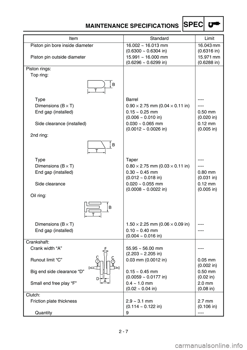
2 - 7 Piston pin bore inside diameter 16.002 ~ 16.013 mm
(0.6300 ~ 0.6304 in)16.043 mm
(0.6316 in)
Piston pin outside diameter 15.991 ~ 16.000 mm
(0.6296 ~ 0.6299 in)15.971 mm
(0.6288 in)
Piston rings:
Top ring:
Type Barrel ----
Dimensions (B × T) 0.90 × 2.75 mm (0.04 × 0.11 in) ----
End gap (installed) 0.15 ~ 0.25 mm
(0.006 ~ 0.010 in)0.50 mm
(0.020 in)
Side clearance (installed) 0.030 ~ 0.065 mm
(0.0012 ~ 0.0026 in)0.12 mm
(0.005 in)
2nd ring:
Type Taper ----
Dimensions (B × T) 0.80 × 2.75 mm (0.03 × 0.11 in) ----
End gap (installed) 0.30 ~ 0.45 mm
(0.012 ~ 0.018 in)0.80 mm
(0.031 in)
Side clearance 0.020 ~ 0.055 mm
(0.0008 ~ 0.0022 in)0.12 mm
(0.005 in)
Oil ring:
Dimensions (B × T) 1.50 × 2.25 mm (0.06 × 0.09 in) ----
End gap (installed) 0.10 ~ 0.40 mm
(0.004 ~ 0.016 in)----
Crankshaft:
Crank width “A”55.95 ~ 56.00 mm
(2.203 ~ 2.205 in)----
Runout limit “C”0.03 mm (0.0012 in) 0.05 mm
(0.002 in)
Big end side clearance “D”0.15 ~ 0.45 mm
(0.0059 ~ 0.0177 in)0.50 mm
(0.02 in)
Small end free play “F”0.4 ~ 1.0 mm
(0.02 ~ 0.04 in)2.0 mm
(0.08 in)
Clutch:
Friction plate thickness 2.9 ~ 3.1 mm
(0.114 ~ 0.122 in)2.7 mm
(0.106 in)
Quantity 9 ----Item Standard Limit
T
B
B
T
B
T
MAINTENANCE SPECIFICATIONS
Page 82 of 674
SPEC
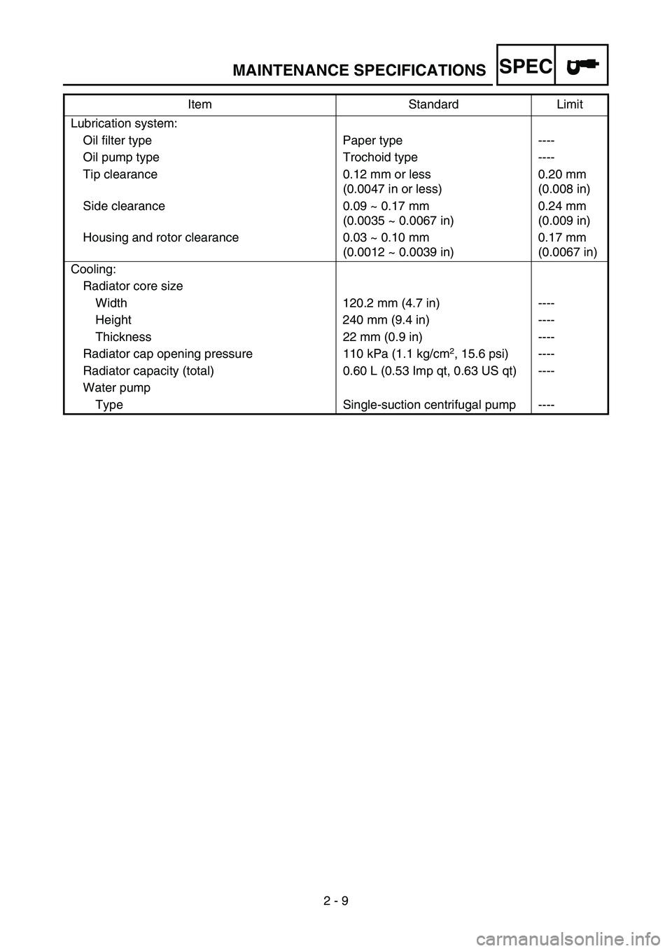
2 - 9 Lubrication system:
Oil filter type Paper type ----
Oil pump type Trochoid type ----
Tip clearance 0.12 mm or less
(0.0047 in or less)0.20 mm
(0.008 in)
Side clearance 0.09 ~ 0.17 mm
(0.0035 ~ 0.0067 in)0.24 mm
(0.009 in)
Housing and rotor clearance 0.03 ~ 0.10 mm
(0.0012 ~ 0.0039 in)0.17 mm
(0.0067 in)
Cooling:
Radiator core size
Width 120.2 mm (4.7 in) ----
Height 240 mm (9.4 in) ----
Thickness 22 mm (0.9 in) ----
Radiator cap opening pressure 110 kPa (1.1 kg/cm
2, 15.6 psi) ----
Radiator capacity (total) 0.60 L (0.53 Imp qt, 0.63 US qt) ----
Water pump
Type Single-suction centrifugal pump ----Item Standard Limit
MAINTENANCE SPECIFICATIONS
Page 83 of 674
SPEC
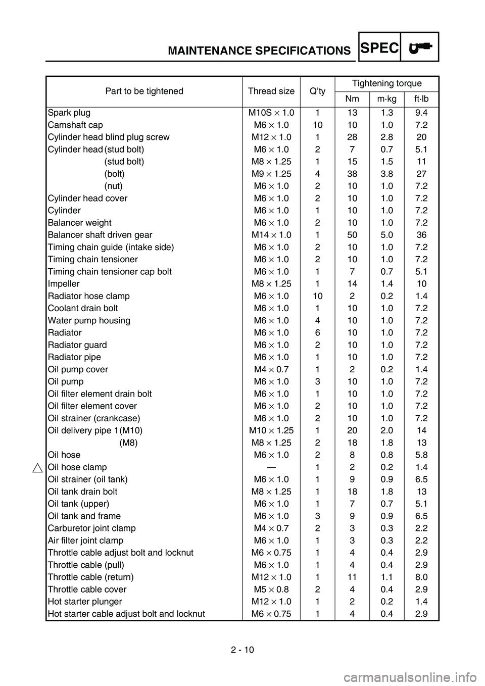
2 - 10 Part to be tightened Thread size Q’tyTightening torque
Nm m·kg ft·lb
Spark plug M10S × 1.0 1 13 1.3 9.4
Camshaft cap M6 × 1.0 10 10 1.0 7.2
Cylinder head blind plug screw M12 × 1.0 1 28 2.8 20
Cylinder head (stud bolt) M6 × 1.0 2 7 0.7 5.1
(stud bolt) M8 × 1.25 1 15 1.5 11
(bolt) M9 × 1.25 4 38 3.8 27
(nut) M6 × 1.0 2 10 1.0 7.2
Cylinder head cover M6 × 1.0 2 10 1.0 7.2
Cylinder M6 × 1.0 1 10 1.0 7.2
Balancer weight M6 × 1.0 2 10 1.0 7.2
Balancer shaft driven gear M14 × 1.0 1 50 5.0 36
Timing chain guide (intake side) M6 × 1.0 2 10 1.0 7.2
Timing chain tensioner M6 × 1.0 2 10 1.0 7.2
Timing chain tensioner cap bolt M6 × 1.0 1 7 0.7 5.1
Impeller M8 × 1.25 1 14 1.4 10
Radiator hose clamp M6 × 1.0 10 2 0.2 1.4
Coolant drain bolt M6 × 1.0 1 10 1.0 7.2
Water pump housing M6 × 1.0 4 10 1.0 7.2
Radiator M6 × 1.0 6 10 1.0 7.2
Radiator guard M6 × 1.0 2 10 1.0 7.2
Radiator pipe M6 × 1.0 1 10 1.0 7.2
Oil pump cover M4 × 0.7 1 2 0.2 1.4
Oil pump M6 × 1.0 3 10 1.0 7.2
Oil filter element drain bolt M6 × 1.0 1 10 1.0 7.2
Oil filter element cover M6 × 1.0 2 10 1.0 7.2
Oil strainer (crankcase) M6 × 1.0 2 10 1.0 7.2
Oil delivery pipe 1 (M10) M10 × 1.25 1 20 2.0 14
(M8) M8 × 1.25 2 18 1.8 13
Oil hose M6 × 1.0 2 8 0.8 5.8
Oil hose clamp—120.21.4
Oil strainer (oil tank) M6 × 1.0 1 9 0.9 6.5
Oil tank drain bolt M8 × 1.25 1 18 1.8 13
Oil tank (upper) M6 × 1.0 1 7 0.7 5.1
Oil tank and frame M6 × 1.0 3 9 0.9 6.5
Carburetor joint clamp M4 × 0.7 2 3 0.3 2.2
Air filter joint clamp M6 × 1.0 1 3 0.3 2.2
Throttle cable adjust bolt and locknut M6 × 0.75 1 4 0.4 2.9
Throttle cable (pull) M6 × 1.0 1 4 0.4 2.9
Throttle cable (return) M12 × 1.0 1 11 1.1 8.0
Throttle cable cover M5 × 0.8 2 4 0.4 2.9
Hot starter plunger M12 × 1.0 1 2 0.2 1.4
Hot starter cable adjust bolt and locknut M6 × 0.75 1 4 0.4 2.9
MAINTENANCE SPECIFICATIONS
Page 84 of 674

SPEC
2 - 11
NOTE:
- marked portion shall be checked for torque tightening after break-in or before each race. Air filter case M6 × 1.0 2 8 0.8 5.8
Air filter joint and air filter case M5 × 0.8 1 4 0.4 2.9
Air filter element M6 × 1.0 1 2 0.2 1.4
Exhaust pipe (nut) M8 × 1.25 1 13 1.3 9.4
(bolt) M8 × 1.25 1 24 2.4 17
Exhaust pipe protector M6 × 1.0 3 10 1.0 7.2
Silencer M8 × 1.25 2 35 3.5 25
Silencer clamp M8 × 1.25 1 16 1.6 11
Crankcase M6 × 1.0 11 12 1.2 8.7
Crankcase bearing stopper M6 × 1.0 11 10 1.0 7.2
Crankcase bearing stopper (crankshaft) M6 × 1.0 4 10 1.0 7.2
Oil level check window holder M6 × 1.0 1 10 1.0 7.2
Left crankcase cover M6 × 1.0 8 10 1.0 7.2
Right crankcase cover M6 × 1.0 8 10 1.0 7.2
Clutch cover M6 × 1.0 7 10 1.0 7.2
Crankcase oil drain bolt M10 × 1.25 1 20 2.0 14
Drive chain sprocket cover M6 × 1.0 2 8 0.8 5.8
Kick shaft ratchet wheel guide M6 × 1.0 2 12 1.2 8.7
Kickstarter crank M8 × 1.25 1 33 3.3 24
Primary drive gear M18 × 1.0 1 75 7.5 54
Clutch spring M6 × 1.0 5 10 1.0 7.2
Clutch boss M16 × 1.0 1 60 6.0 43
Clutch cable locknut M8 × 1.25 1 7 0.7 5.1
Clutch cable adjust bolt and locknut M6 × 0.75 1 4 0.4 2.9
Push lever shaft M6 × 1.0 1 10 1.0 7.2
Drive sprocket M18 × 1.0 1 75 7.5 54
Drive axle oil seal stopper M6 × 1.0 2 10 1.0 7.2
Segment M8 × 1.25 1 30 3.0 22
Shift guide M6 × 1.0 2 10 1.0 7.2
Stopper lever M6 × 1.0 1 10 1.0 7.2
Shift pedal M6 × 1.0 1 12 1.2 8.7 Part to be tightened Thread size Q’tyTightening torque
Nm m·kg ft·lb
MAINTENANCE SPECIFICATIONS
Page 85 of 674
SPEC
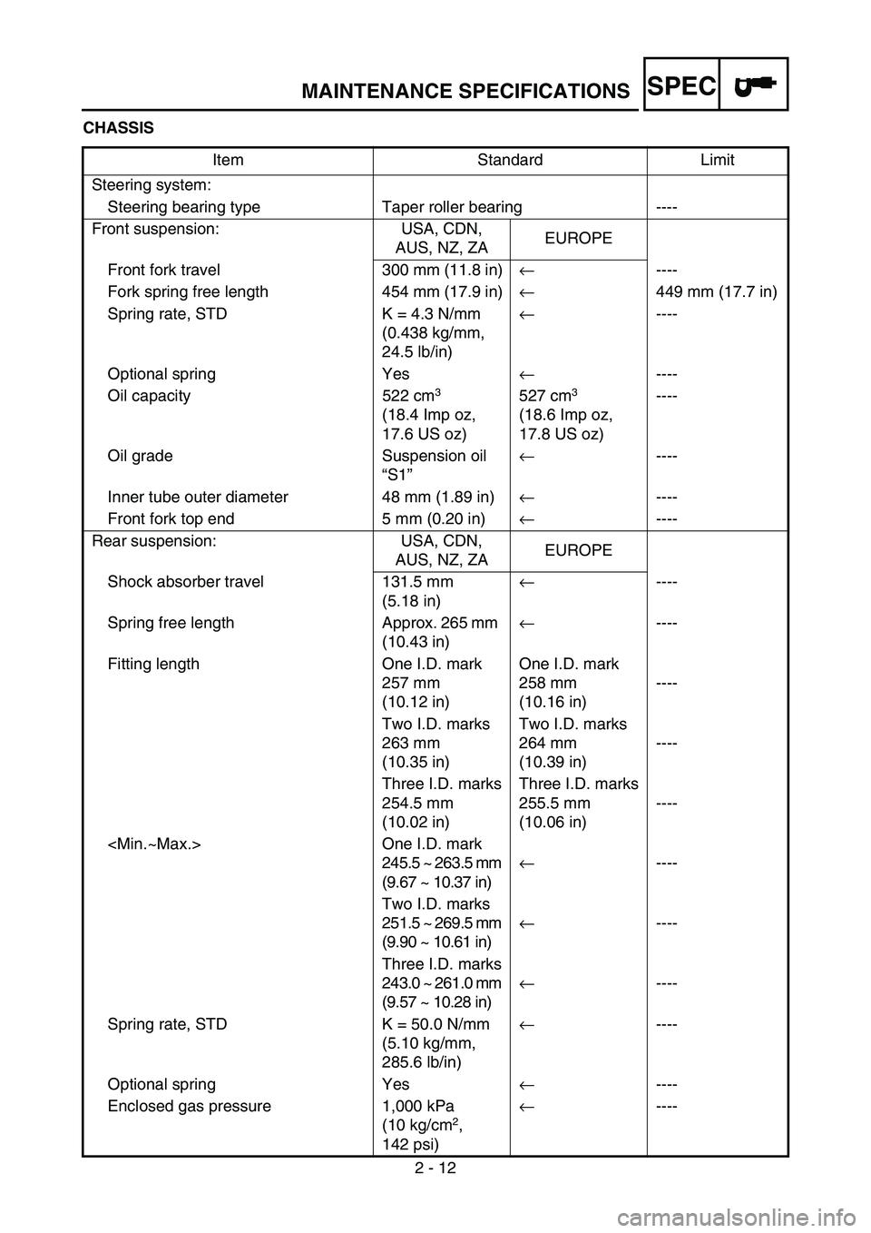
2 - 12 CHASSIS
Item Standard Limit
Steering system:
Steering bearing type Taper roller bearing ----
Front suspension: USA, CDN,
AUS, NZ, ZAEUROPE
Front fork travel 300 mm (11.8 in)← ----
Fork spring free length 454 mm (17.9 in)← 449 mm (17.7 in)
Spring rate, STD K = 4.3 N/mm
(0.438 kg/mm,
24.5 lb/in)← ----
Optional spring Yes← ----
Oil capacity 522 cm
3
(18.4 Imp oz,
17.6 US oz) 527 cm3
(18.6 Imp oz,
17.8 US oz) ----
Oil grade Suspension oil
“S1”← ----
Inner tube outer diameter 48 mm (1.89 in)← ----
Front fork top end 5 mm (0.20 in)← ----
Rear suspension: USA, CDN,
AUS, NZ, ZAEUROPE
Shock absorber travel 131.5 mm
(5.18 in)← ----
Spring free length Approx. 265 mm
(10.43 in)← ----
Fitting length One I.D. mark
257 mm
(10.12 in)One I.D. mark
258 mm
(10.16 in)----
Two I.D. marks
263 mm
(10.35 in)Two I.D. marks
264 mm
(10.39 in)----
Three I.D. marks
254.5 mm
(10.02 in)Three I.D. marks
255.5 mm
(10.06 in)----
245.5 ~ 263.5 mm
(9.67 ~ 10.37 in)←----
Two I.D. marks
251.5 ~ 269.5 mm
(9.90 ~ 10.61 in)←----
Three I.D. marks
243.0 ~ 261.0 mm
(9.57 ~ 10.28 in)←----
Spring rate, STD K = 50.0 N/mm
(5.10 kg/mm,
285.6 lb/in)←----
Optional spring Yes← ----
Enclosed gas pressure 1,000 kPa
(10 kg/cm
2,
142 psi)← ----
MAINTENANCE SPECIFICATIONS
Page 89 of 674
SPEC
2 - 16
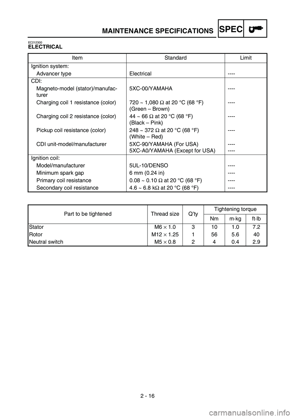
EC212300
ELECTRICAL
Item Standard Limit
Ignition system:
Advancer type Electrical ----
CDI:
Magneto-model (stator)/manufac-
turer5XC-00/YAMAHA ----
Charging coil 1 resistance (color) 720 ~ 1,080 Ω at 20 °C (68 °F)
(Green – Brown)----
Charging coil 2 resistance (color) 44 ~ 66 Ω at 20°C (68 °F)
(Black – Pink)----
Pickup coil resistance (color) 248 ~ 372 Ω at 20°C (68 °F)
(White – Red)----
CDI unit-model/manufacturer 5XC-90/YAMAHA (For USA)
5XC-A0/YAMAHA (Except for USA)----
----
Ignition coil:
Model/manufacturer 5UL-10/DENSO ----
Minimum spark gap 6 mm (0.24 in) ----
Primary coil resistance 0.08 ~ 0.10 Ω at 20 °C (68 °F) ----
Secondary coil resistance 4.6 ~ 6.8 kΩ at 20 °C (68 °F) ----
Part to be tightened Thread size Q’tyTightening torque
Nm m·kg ft·lb
Stator M6 × 1.0 3 10 1.0 7.2
Rotor M12 × 1.25 1 56 5.6 40
Neutral switch M5 × 0.8 2 4 0.4 2.9
MAINTENANCE SPECIFICATIONS
Page 103 of 674
SPEC
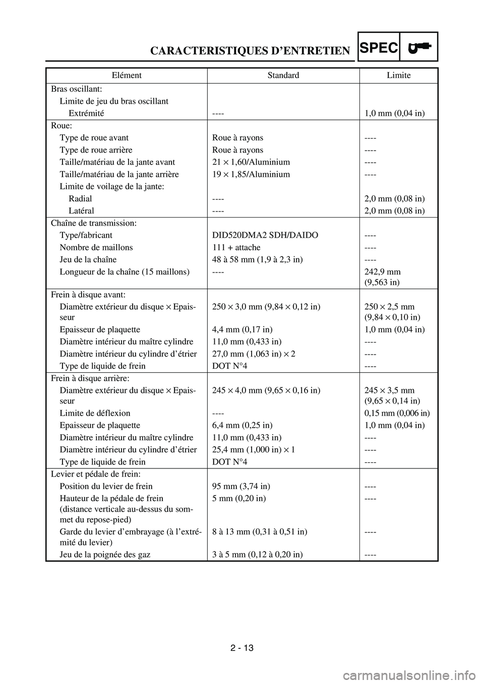
2 - 13 Bras oscillant:
Limite de jeu du bras oscillant
Extrémité---- 1,0 mm (0,04 in)
Roue:
Type de roue avant Roue à rayons ----
Type de roue arrière Roue à rayons ----
Taille/matériau de la jante avant 21 × 1,60/Aluminium ----
Taille/matériau de la jante arrière 19 × 1,85/Aluminium ----
Limite de voilage de la jante:
Radial ---- 2,0 mm (0,08 in)
Latéral ---- 2,0 mm (0,08 in)
Chaîne de transmission:
Type/fabricant DID520DMA2 SDH/DAIDO ----
Nombre de maillons 111 + attache ----
Jeu de la chaîne 48 à 58 mm (1,9 à 2,3 in) ----
Longueur de la chaîne (15 maillons) ---- 242,9 mm
(9,563 in)
Frein à disque avant:
Diamètre extérieur du disque × Epais-
seur250 × 3,0 mm (9,84 × 0,12 in) 250 × 2,5 mm
(9,84 × 0,10 in)
Epaisseur de plaquette 4,4 mm (0,17 in) 1,0 mm (0,04 in)
Diamètre intérieur du maître cylindre 11,0 mm (0,433 in) ----
Diamètre intérieur du cylindre d’étrier 27,0 mm (1,063 in) × 2 ----
Type de liquide de frein DOT N°4 ----
Frein à disque arrière:
Diamètre extérieur du disque × Epais-
seur245 × 4,0 mm (9,65 × 0,16 in) 245 × 3,5 mm
(9,65 × 0,14 in)
Limite de déflexion ---- 0,15 mm (0,006 in)
Epaisseur de plaquette 6,4 mm (0,25 in) 1,0 mm (0,04 in)
Diamètre intérieur du maître cylindre 11,0 mm (0,433 in) ----
Diamètre intérieur du cylindre d’étrier 25,4 mm (1,000 in) × 1 ----
Type de liquide de frein DOT N°4 ----
Levier et pédale de frein:
Position du levier de frein 95 mm (3,74 in) ----
Hauteur de la pédale de frein
(distance verticale au-dessus du som-
met du repose-pied)5 mm (0,20 in) ----
Garde du levier d’embrayage (à l’extré-
mité du levier)8 à 13 mm (0,31 à 0,51 in) ----
Jeu de la poignée des gaz 3 à 5 mm (0,12 à 0,20 in) ---- Elément Standard Limite
CARACTERISTIQUES D’ENTRETIEN
Page 144 of 674
2 - 19
SPECCABLE ROUTING DIAGRAM
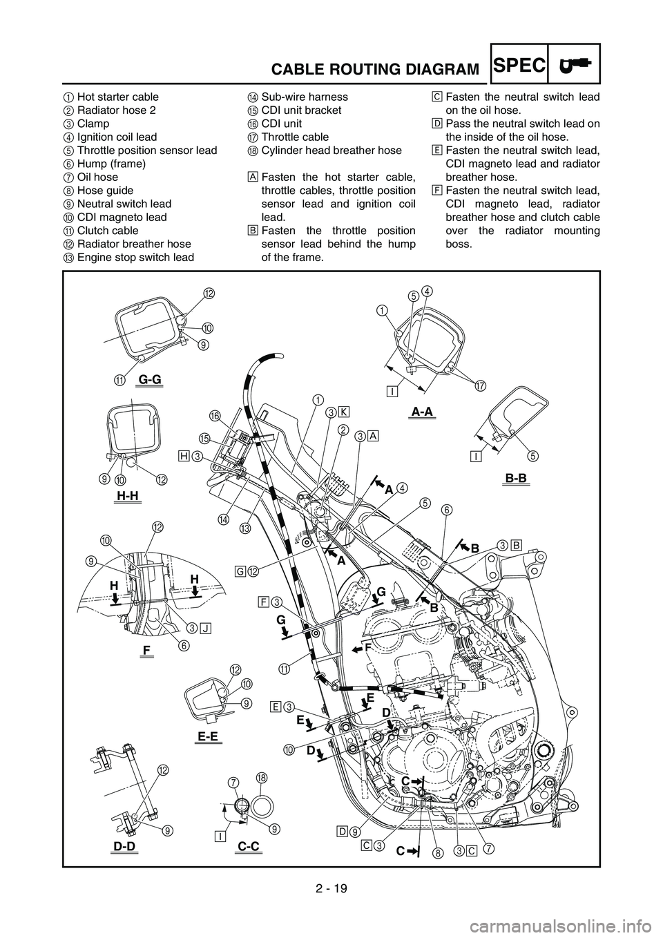
1Hot starter cable
2Radiator hose 2
3Clamp
4Ignition coil lead
5Throttle position sensor lead
6Hump (frame)
7Oil hose
8Hose guide
9Neutral switch lead
0CDI magneto lead
AClutch cable
BRadiator breather hose
CEngine stop switch leadDSub-wire harness
ECDI unit bracket
FCDI unit
GThrottle cable
HCylinder head breather hose
ÈFasten the hot starter cable,
throttle cables, throttle position
sensor lead and ignition coil
lead.
ÉFasten the throttle position
sensor lead behind the hump
of the frame.ÊFasten the neutral switch lead
on the oil hose.
ËPass the neutral switch lead on
the inside of the oil hose.
ÌFasten the neutral switch lead,
CDI magneto lead and radiator
breather hose.
ÍFasten the neutral switch lead,
CDI magneto lead, radiator
breather hose and clutch cable
over the radiator mounting
boss.
5Ð
Ð
B-B
C-C
E-E
H-H
G-G
D-D
A-A
G
4
5
1
7H
Ð B
B
0
9 F
3
Ñ
6 90F
È
9
CC
C E HH
GA
AB
E
7
3
8 3 9
Ê Ê
Ë
F
E
3
D
C
B
3
A
3
Ì Í Î Ï
1
2
3
4
5
6
3
B
0
9
A
0É
B
B 0 9
9
D
G
B
D
Ò 3
Page 148 of 674
2 - 21
SPEC
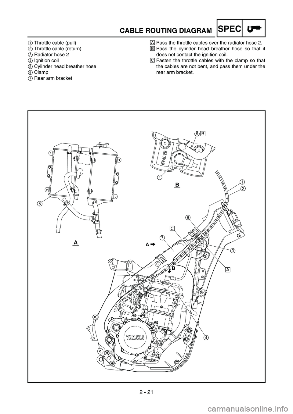
1Throttle cable (pull)
2Throttle cable (return)
3Radiator hose 2
4Ignition coil
5Cylinder head breather hose
6Clamp
7Rear arm bracketÈPass the throttle cables over the radiator hose 2.
ÉPass the cylinder head breather hose so that it
does not contact the ignition coil.
ÊFasten the throttle cables with the clamp so that
the cables are not bent, and pass them under the
rear arm bracket.
Ê
A
B
5
4É
A
B
1
2
4È
5
3
6
7
CABLE ROUTING DIAGRAM