oil YAMAHA YZ250F 2006 Manuale duso (in Italian)
[x] Cancel search | Manufacturer: YAMAHA, Model Year: 2006, Model line: YZ250F, Model: YAMAHA YZ250F 2006Pages: 674, PDF Dimensioni: 21.07 MB
Page 254 of 674

3 - 46
INSP
ADJ
IGNITION TIMING CHECK
IGNITION TIMING CHECK
1. Remove:
Timing mark accessing screw 1
2. Attach:
Timing light
Inductive tachometer
To the ignition coil lead (orange lead 1).
Timing light:
YM-33277-A/90890-03141
1
3. Adjust:
Engine idling speed
Refer to “ENGINE IDLING SPEED
ADJUSTMENT” section.
4. Check:
Ignition timing
Visually check the stationary pointer a is
within the firing range b on the rotor.
Incorrect firing range → Check rotor and
pickup assembly.
5. Install:
Timing mark accessing screw
Page 308 of 674
4 - 27
ENGCAMSHAFTS
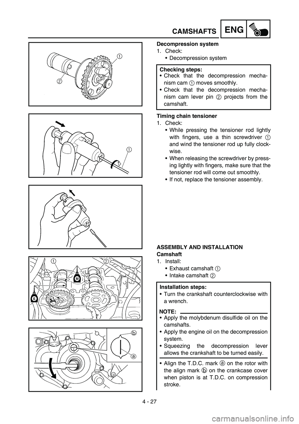
Decompression system
1. Check:
Decompression system
Timing chain tensioner
1. Check:
While pressing the tensioner rod lightly
with fingers, use a thin screwdriver 1
and wind the tensioner rod up fully clock-
wise.
When releasing the screwdriver by press-
ing lightly with fingers, make sure that the
tensioner rod will come out smoothly.
If not, replace the tensioner assembly.
ASSEMBLY AND INSTALLATION
Camshaft
1. Install:
Exhaust camshaft 1
Intake camshaft 2 Checking steps:
Check that the decompression mecha-
nism cam 1 moves smoothly.
Check that the decompression mecha-
nism cam lever pin 2 projects from the
camshaft.
Installation steps:
Turn the crankshaft counterclockwise with
a wrench.
NOTE:
Apply the molybdenum disulfide oil on the
camshafts.
Apply the engine oil on the decompression
system.
Squeezing the decompression lever
allows the crankshaft to be turned easily.
Align the T.D.C. mark a on the rotor with
the align mark b on the crankcase cover
when piston is at T.D.C. on compression
stroke.
Page 310 of 674
4 - 28
ENGCAMSHAFTS
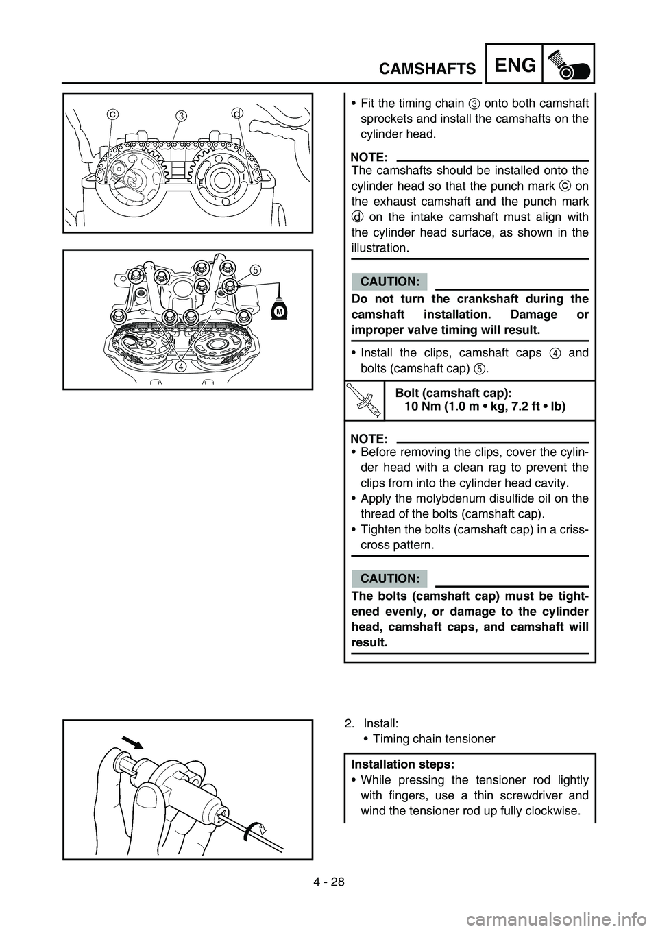
Fit the timing chain 3 onto both camshaft
sprockets and install the camshafts on the
cylinder head.
NOTE:
The camshafts should be installed onto the
cylinder head so that the punch mark c on
the exhaust camshaft and the punch mark
d on the intake camshaft must align with
the cylinder head surface, as shown in the
illustration.
CAUTION:
Do not turn the crankshaft during the
camshaft installation. Damage or
improper valve timing will result.
Install the clips, camshaft caps 4 and
bolts (camshaft cap) 5.
T R..
Bolt (camshaft cap):
10 Nm (1.0 m kg, 7.2 ft lb)
NOTE:
Before removing the clips, cover the cylin-
der head with a clean rag to prevent the
clips from into the cylinder head cavity.
Apply the molybdenum disulfide oil on the
thread of the bolts (camshaft cap).
Tighten the bolts (camshaft cap) in a criss-
cross pattern.
CAUTION:
The bolts (camshaft cap) must be tight-
ened evenly, or damage to the cylinder
head, camshaft caps, and camshaft will
result.
5
4
M
2. Install:
Timing chain tensioner
Installation steps:
While pressing the tensioner rod lightly
with fingers, use a thin screwdriver and
wind the tensioner rod up fully clockwise.
Page 314 of 674
4 - 30
ENG
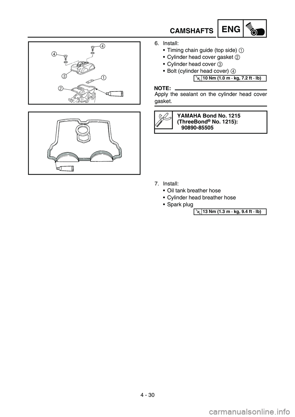
6. Install:
Timing chain guide (top side) 1
Cylinder head cover gasket 2
Cylinder head cover 3
Bolt (cylinder head cover) 4
NOTE:
Apply the sealant on the cylinder head cover
gasket.
YAMAHA Bond No. 1215
(ThreeBond® No. 1215):
90890-85505
T R..10 Nm (1.0 m · kg, 7.2 ft · lb)
7. Install:
Oil tank breather hose
Cylinder head breather hose
Spark plug
T R..13 Nm (1.3 m · kg, 9.4 ft · lb)
CAMSHAFTS
Page 316 of 674
4 - 31
ENGCYLINDER HEAD
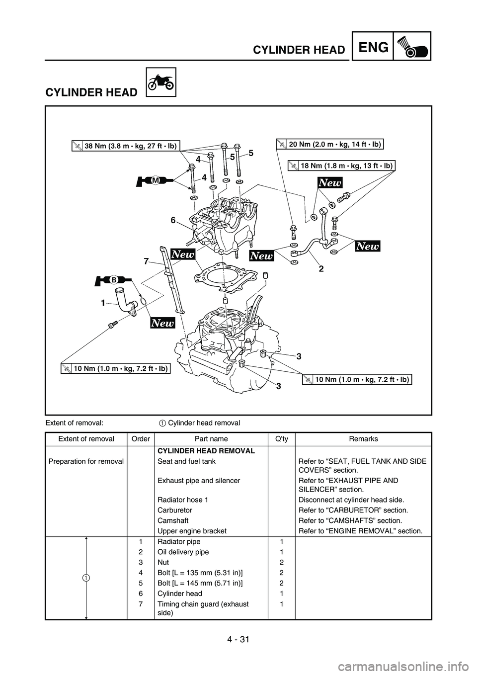
CYLINDER HEAD
Extent of removal:
1 Cylinder head removal
Extent of removal Order Part name Q’ty Remarks
CYLINDER HEAD REMOVAL
Preparation for removal Seat and fuel tank Refer to “SEAT, FUEL TANK AND SIDE
COVERS” section.
Exhaust pipe and silencer Refer to “EXHAUST PIPE AND
SILENCER” section.
Radiator hose 1 Disconnect at cylinder head side.
Carburetor Refer to “CARBURETOR” section.
Camshaft Refer to “CAMSHAFTS” section.
Upper engine bracket Refer to “ENGINE REMOVAL” section.
1 Radiator pipe 1
2 Oil delivery pipe 1
3Nut 2
4 Bolt [L = 135 mm (5.31 in)] 2
5 Bolt [L = 145 mm (5.71 in)] 2
6 Cylinder head 1
7 Timing chain guard (exhaust
side)1
1
Page 320 of 674
4 - 33
ENGCYLINDER HEAD
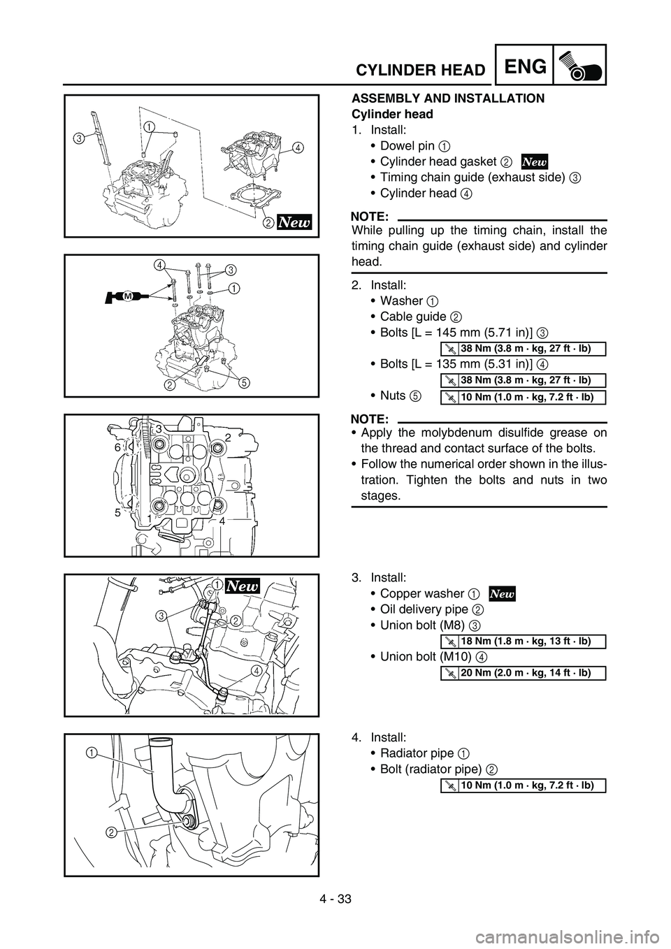
ASSEMBLY AND INSTALLATION
Cylinder head
1. Install:
Dowel pin 1
Cylinder head gasket 2
Timing chain guide (exhaust side) 3
Cylinder head 4
NOTE:
While pulling up the timing chain, install the
timing chain guide (exhaust side) and cylinder
head.
2. Install:
Washer 1
Cable guide 2
Bolts [L = 145 mm (5.71 in)] 3
Bolts [L = 135 mm (5.31 in)] 4
Nuts 5
NOTE:
Apply the molybdenum disulfide grease on
the thread and contact surface of the bolts.
Follow the numerical order shown in the illus-
tration. Tighten the bolts and nuts in two
stages.
T R..38 Nm (3.8 m · kg, 27 ft · lb)
T R..38 Nm (3.8 m · kg, 27 ft · lb)
T R..10 Nm (1.0 m · kg, 7.2 ft · lb)
3. Install:
Copper washer 1
Oil delivery pipe 2
Union bolt (M8) 3
Union bolt (M10) 4
T R..18 Nm (1.8 m · kg, 13 ft · lb)
T R..20 Nm (2.0 m · kg, 14 ft · lb)
4. Install:
Radiator pipe 1
Bolt (radiator pipe) 2
2 1
T R..10 Nm (1.0 m · kg, 7.2 ft · lb)
Page 330 of 674
4 - 38
ENGVALVES AND VALVE SPRINGS
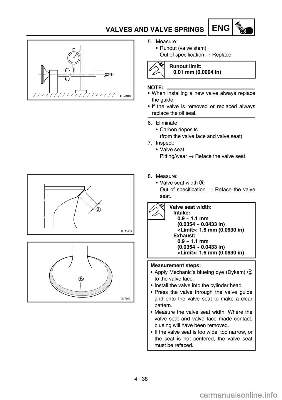
5. Measure:
Runout (valve stem)
Out of specification → Replace.
NOTE:
When installing a new valve always replace
the guide.
If the valve is removed or replaced always
replace the oil seal.
6. Eliminate:
Carbon deposits
(from the valve face and valve seat)
7. Inspect:
Valve seat
Pitting/wear → Reface the valve seat.
Runout limit:
0.01 mm (0.0004 in)
8. Measure:
Valve seat width a
Out of specification → Reface the valve
seat.
Valve seat width:
Intake:
0.9 ~ 1.1 mm
(0.0354 ~ 0.0433 in)
Exhaust:
0.9 ~ 1.1 mm
(0.0354 ~ 0.0433 in)
Measurement steps:
Apply Mechanic’s blueing dye (Dykem) b
to the valve face.
Install the valve into the cylinder head.
Press the valve through the valve guide
and onto the valve seat to make a clear
pattern.
Measure the valve seat width. Where the
valve seat and valve face made contact,
blueing will have been removed.
If the valve seat is too wide, too narrow, or
the seat is not centered, the valve seat
must be refaced.
Page 332 of 674
4 - 39
ENGVALVES AND VALVE SPRINGS
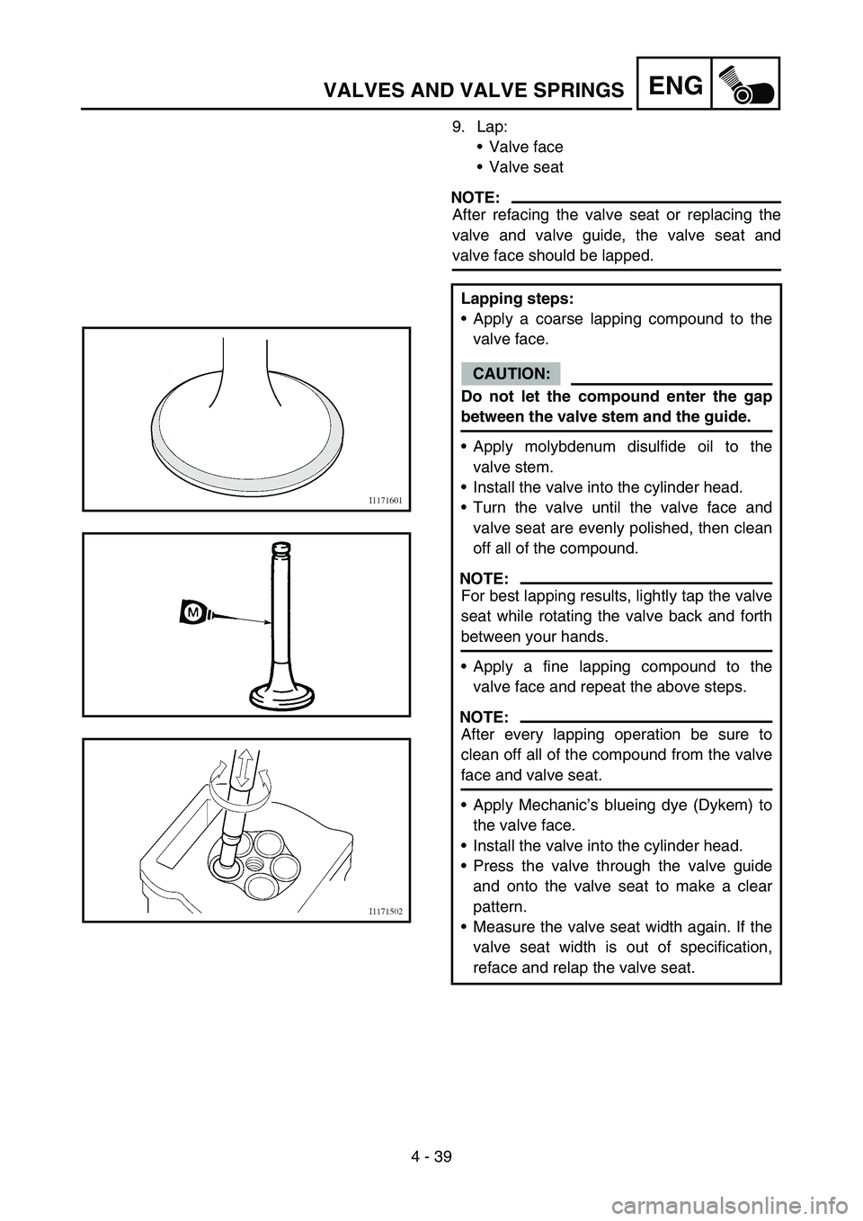
9. Lap:
Valve face
Valve seat
NOTE:
After refacing the valve seat or replacing the
valve and valve guide, the valve seat and
valve face should be lapped.
Lapping steps:
Apply a coarse lapping compound to the
valve face.
CAUTION:
Do not let the compound enter the gap
between the valve stem and the guide.
Apply molybdenum disulfide oil to the
valve stem.
Install the valve into the cylinder head.
Turn the valve until the valve face and
valve seat are evenly polished, then clean
off all of the compound.
NOTE:
For best lapping results, lightly tap the valve
seat while rotating the valve back and forth
between your hands.
Apply a fine lapping compound to the
valve face and repeat the above steps.
NOTE:
After every lapping operation be sure to
clean off all of the compound from the valve
face and valve seat.
Apply Mechanic’s blueing dye (Dykem) to
the valve face.
Install the valve into the cylinder head.
Press the valve through the valve guide
and onto the valve seat to make a clear
pattern.
Measure the valve seat width again. If the
valve seat width is out of specification,
reface and relap the valve seat.
Page 336 of 674
4 - 41
ENGVALVES AND VALVE SPRINGS
ASSEMBLY AND INSTALLATION
Valve and valve spring
1. Apply:
Molybdenum disulfide oil
Onto the valve stem and valve stem seal.
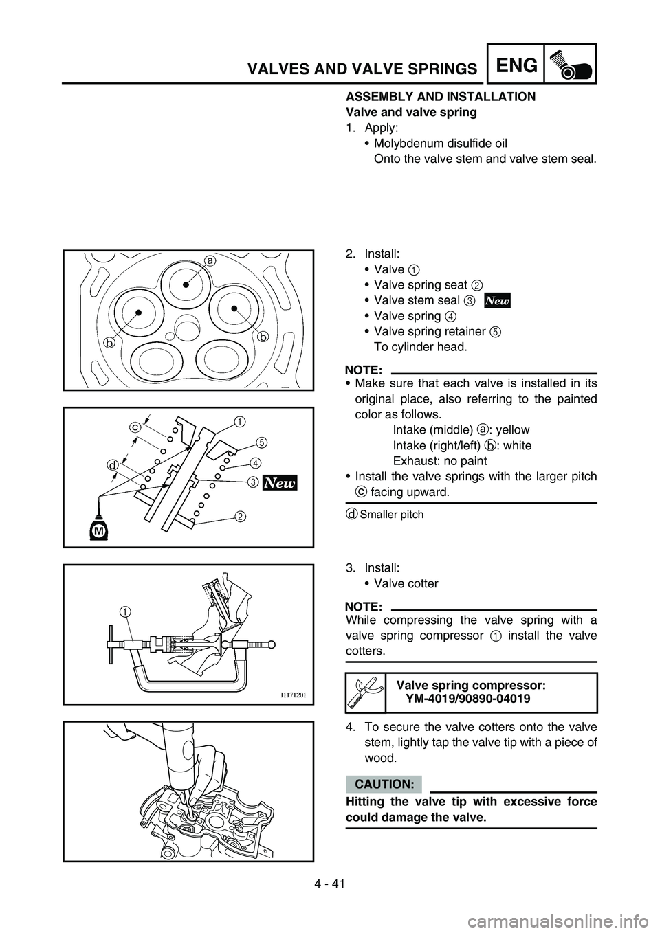
2. Install:
Valve 1
Valve spring seat 2
Valve stem seal 3
Valve spring 4
Valve spring retainer 5
To cylinder head.
NOTE:
Make sure that each valve is installed in its
original place, also referring to the painted
color as follows.
Intake (middle) a: yellow
Intake (right/left) b: white
Exhaust: no paint
Install the valve springs with the larger pitch
c facing upward.
d
Smaller pitch
3. Install:
Valve cotter
NOTE:
While compressing the valve spring with a
valve spring compressor 1 install the valve
cotters.
4. To secure the valve cotters onto the valve
stem, lightly tap the valve tip with a piece of
wood.
CAUTION:
Hitting the valve tip with excessive force
could damage the valve.
Valve spring compressor:
YM-4019/90890-04019
Page 338 of 674
4 - 42
ENGVALVES AND VALVE SPRINGS
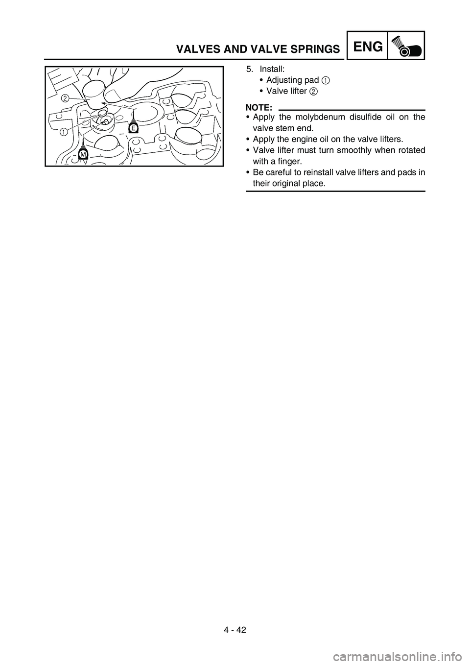
5. Install:
Adjusting pad 1
Valve lifter 2
NOTE:
Apply the molybdenum disulfide oil on the
valve stem end.
Apply the engine oil on the valve lifters.
Valve lifter must turn smoothly when rotated
with a finger.
Be careful to reinstall valve lifters and pads in
their original place.