engine YAMAHA YZ250F 2006 Workshop Manual
[x] Cancel search | Manufacturer: YAMAHA, Model Year: 2006, Model line: YZ250F, Model: YAMAHA YZ250F 2006Pages: 674, PDF Size: 21.07 MB
Page 254 of 674

3 - 46
INSP
ADJ
IGNITION TIMING CHECK
IGNITION TIMING CHECK
1. Remove:
Timing mark accessing screw 1
2. Attach:
Timing light
Inductive tachometer
To the ignition coil lead (orange lead 1).
Timing light:
YM-33277-A/90890-03141
1
3. Adjust:
Engine idling speed
Refer to “ENGINE IDLING SPEED
ADJUSTMENT” section.
4. Check:
Ignition timing
Visually check the stationary pointer a is
within the firing range b on the rotor.
Incorrect firing range → Check rotor and
pickup assembly.
5. Install:
Timing mark accessing screw
Page 256 of 674
4 - 1
ENG
EC400000
ENGINE
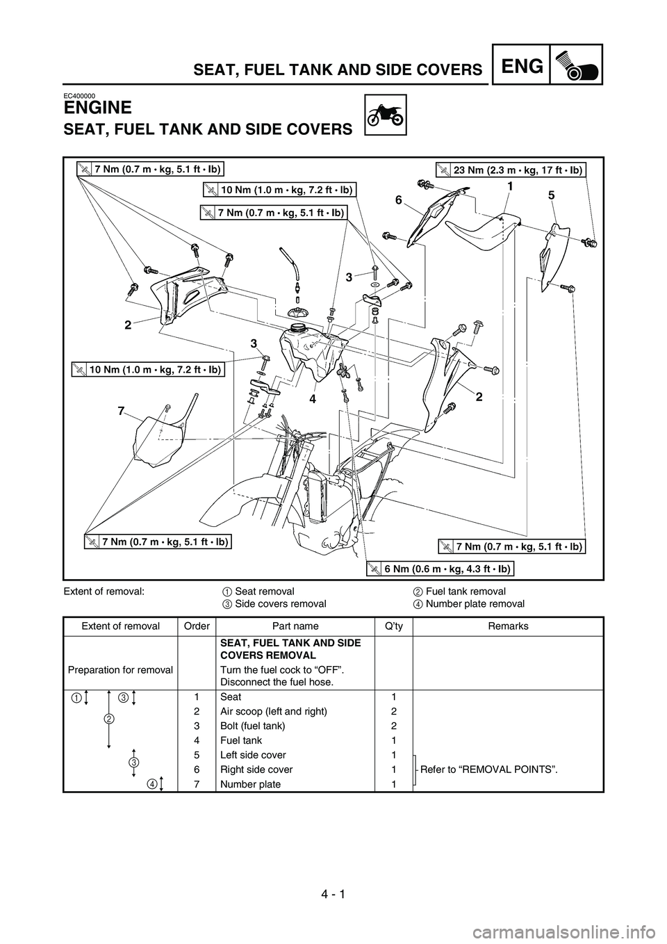
SEAT, FUEL TANK AND SIDE COVERS
Extent of removal:
1 Seat removal
2 Fuel tank removal
3 Side covers removal
4 Number plate removal
Extent of removal Order Part name Q’ty Remarks
SEAT, FUEL TANK AND SIDE
COVERS REMOVAL
Preparation for removal Turn the fuel cock to “OFF”.
Disconnect the fuel hose.
1Seat 1
2 Air scoop (left and right) 2
3 Bolt (fuel tank) 2
4 Fuel tank 1
5 Left side cover 1
Refer to “REMOVAL POINTS”. 6 Right side cover 1
7 Number plate 1
4
2
1
3
3
SEAT, FUEL TANK AND SIDE COVERS
4
Page 268 of 674
4 - 7
ENGRADIATOR
EC456000
HANDLING NOTE
WARNING
Do not remove the radiator cap when the
engine and radiator are hot. Scalding hot
fluid and steam may be blown out under
pressure, which could cause serious
injury.
When the engine has cooled, open the radi-
ator cap by the following procedure:
Place a thick rag, like a towel, over the radi-
ator cap, slowly rotate the cap counter-
clockwise to the detent. This procedure
allows any residual pressure to escape.
When the hissing sound has stopped,
press down on the cap while turning coun-
terclockwise and remove it.
EC454000
INSPECTION
EC444100
Radiator
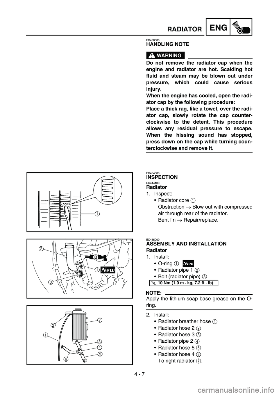
1. Inspect:
Radiator core 1
Obstruction → Blow out with compressed
air through rear of the radiator.
Bent fin → Repair/replace.
EC455000
ASSEMBLY AND INSTALLATION
Radiator
1. Install:
O-ring 1
Radiator pipe 1 2
Bolt (radiator pipe) 3
NOTE:
Apply the lithium soap base grease on the O-
ring.
2. Install:
Radiator breather hose 1
Radiator hose 2 2
Radiator hose 3 3
Radiator pipe 2 4
Radiator hose 5 5
Radiator hose 4 6
To right radiator 7.
1
3 2
B
T R..10 Nm (1.0 m · kg, 7.2 ft · lb)
2
1
67
3
4
5
Page 278 of 674

4 - 12
ENGCARBURETOR
HANDLING NOTE
CAUTION:
Do not loosen the screws (throttle position
sensor)
1 except when changing the throt-
tle position sensor due to failure because it
will cause a drop in engine performance.
1
REMOVAL POINTS
Pilot screw
1. Remove:
Pilot screw 1
NOTE:
To optimize the fuel flow at a small throttle
opening, each machine’s pilot screw has been
individually set at the factory. Before removing
the pilot screw, turn it in fully and count the
number of turns. Record this number as the
factory-set number of turns out.
INSPECTION
Carburetor
1. Inspect:
Carburetor body
Contamination → Clean.
NOTE:
Use a petroleum based solvent for cleaning.
Blow out all passages and jets with com-
pressed air.
Never use a wire.
Page 308 of 674
4 - 27
ENGCAMSHAFTS
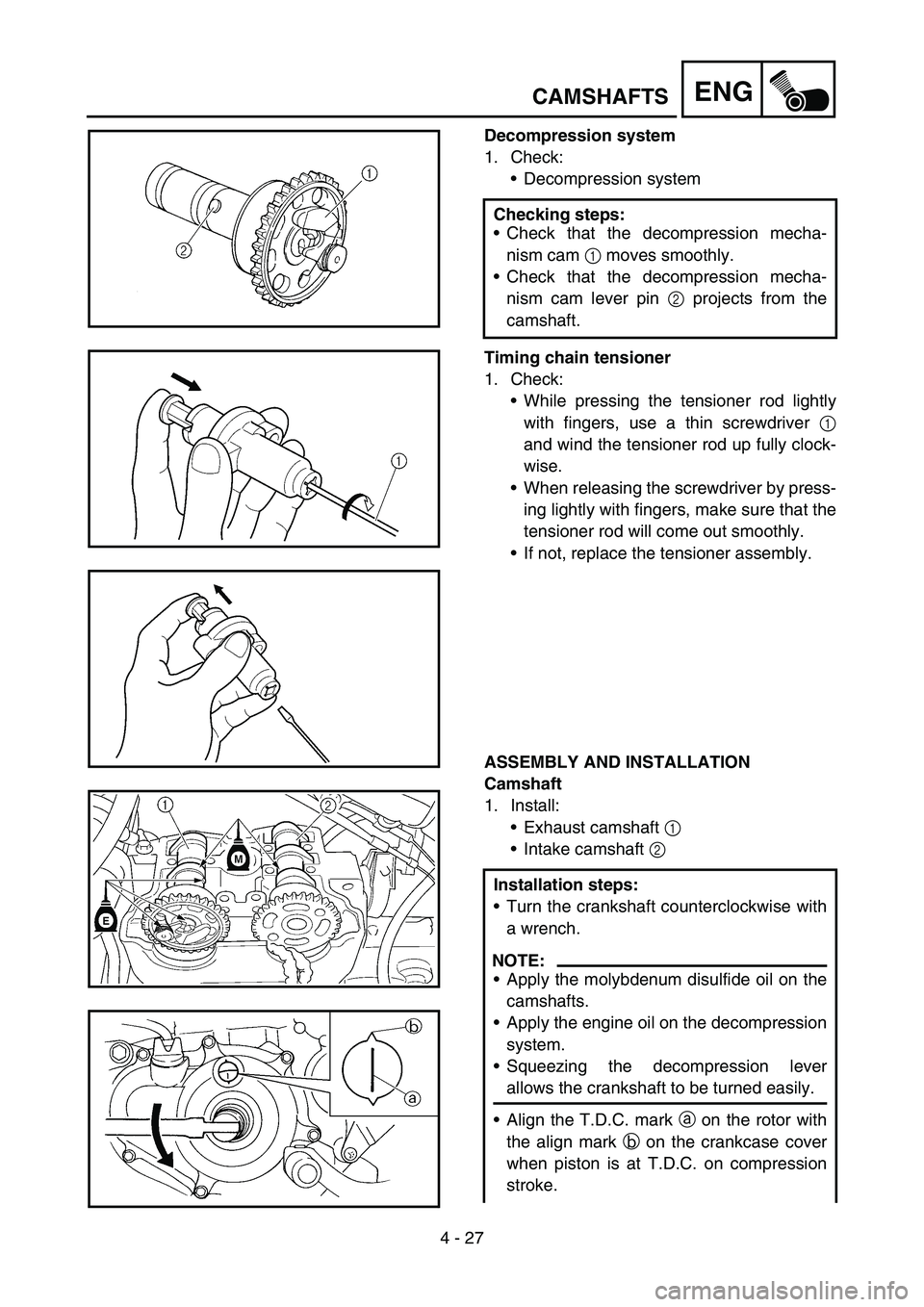
Decompression system
1. Check:
Decompression system
Timing chain tensioner
1. Check:
While pressing the tensioner rod lightly
with fingers, use a thin screwdriver 1
and wind the tensioner rod up fully clock-
wise.
When releasing the screwdriver by press-
ing lightly with fingers, make sure that the
tensioner rod will come out smoothly.
If not, replace the tensioner assembly.
ASSEMBLY AND INSTALLATION
Camshaft
1. Install:
Exhaust camshaft 1
Intake camshaft 2 Checking steps:
Check that the decompression mecha-
nism cam 1 moves smoothly.
Check that the decompression mecha-
nism cam lever pin 2 projects from the
camshaft.
Installation steps:
Turn the crankshaft counterclockwise with
a wrench.
NOTE:
Apply the molybdenum disulfide oil on the
camshafts.
Apply the engine oil on the decompression
system.
Squeezing the decompression lever
allows the crankshaft to be turned easily.
Align the T.D.C. mark a on the rotor with
the align mark b on the crankcase cover
when piston is at T.D.C. on compression
stroke.
Page 316 of 674
4 - 31
ENGCYLINDER HEAD
CYLINDER HEAD
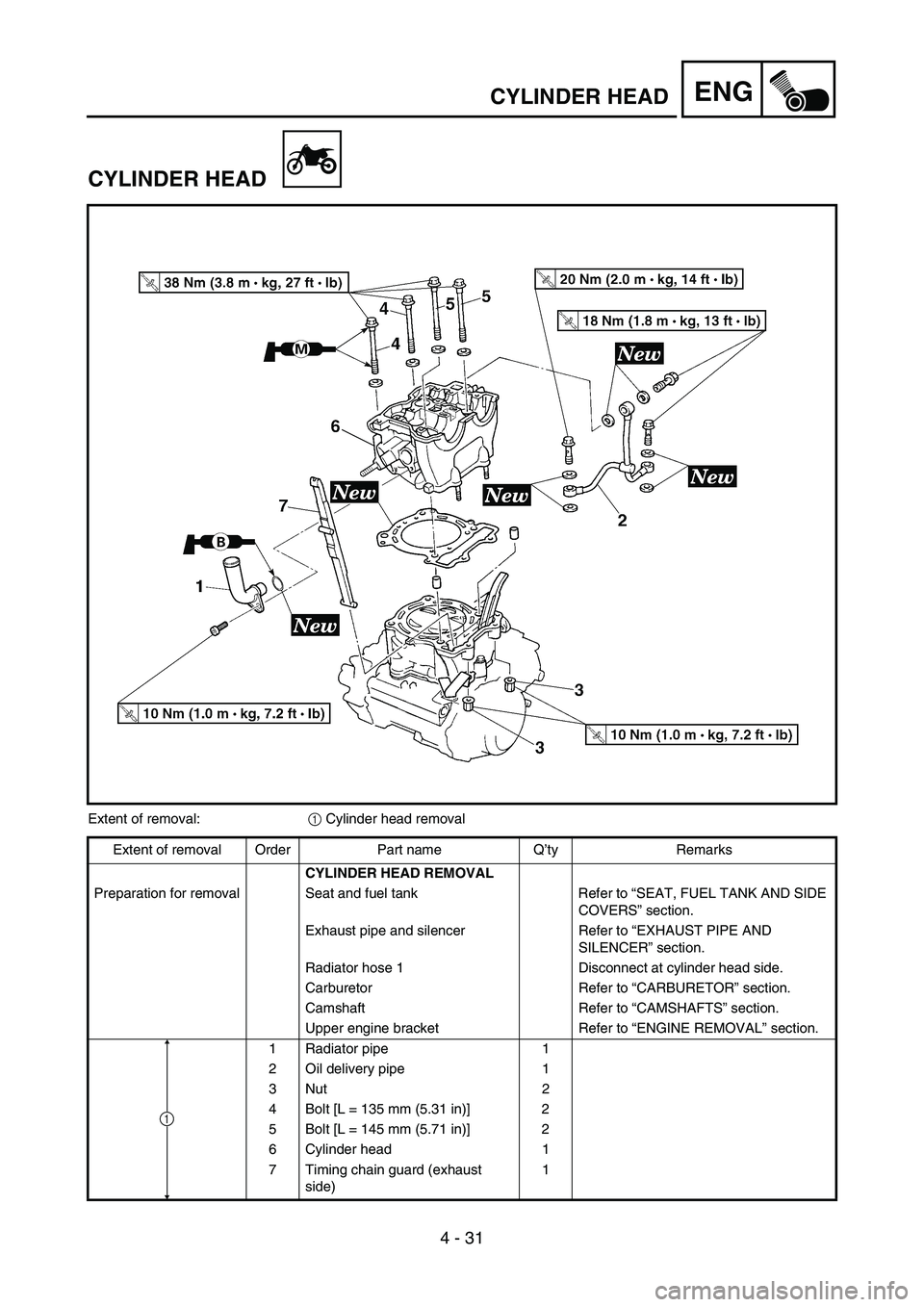
Extent of removal:
1 Cylinder head removal
Extent of removal Order Part name Q’ty Remarks
CYLINDER HEAD REMOVAL
Preparation for removal Seat and fuel tank Refer to “SEAT, FUEL TANK AND SIDE
COVERS” section.
Exhaust pipe and silencer Refer to “EXHAUST PIPE AND
SILENCER” section.
Radiator hose 1 Disconnect at cylinder head side.
Carburetor Refer to “CARBURETOR” section.
Camshaft Refer to “CAMSHAFTS” section.
Upper engine bracket Refer to “ENGINE REMOVAL” section.
1 Radiator pipe 1
2 Oil delivery pipe 1
3Nut 2
4 Bolt [L = 135 mm (5.31 in)] 2
5 Bolt [L = 145 mm (5.71 in)] 2
6 Cylinder head 1
7 Timing chain guard (exhaust
side)1
1
Page 338 of 674
4 - 42
ENGVALVES AND VALVE SPRINGS
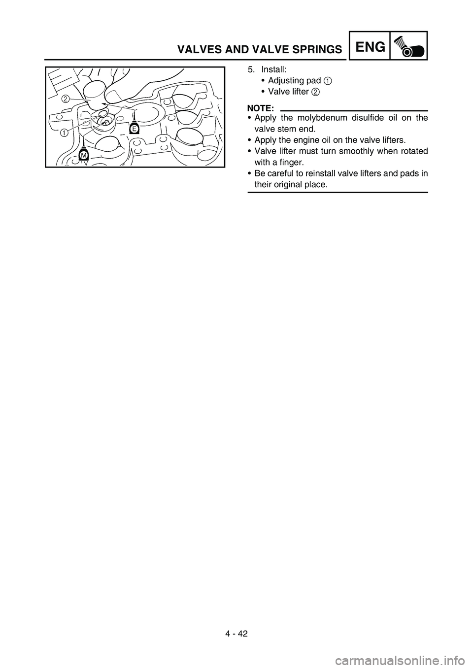
5. Install:
Adjusting pad 1
Valve lifter 2
NOTE:
Apply the molybdenum disulfide oil on the
valve stem end.
Apply the engine oil on the valve lifters.
Valve lifter must turn smoothly when rotated
with a finger.
Be careful to reinstall valve lifters and pads in
their original place.
Page 348 of 674
4 - 47
ENGCYLINDER AND PISTON
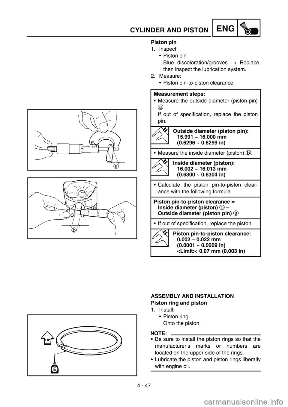
Piston pin
1. Inspect:
Piston pin
Blue discoloration/grooves → Replace,
then inspect the lubrication system.
2. Measure:
Piston pin-to-piston clearance
ASSEMBLY AND INSTALLATION
Piston ring and piston
1. Install:
Piston ring
Onto the piston.
NOTE:
Be sure to install the piston rings so that the
manufacturer’s marks or numbers are
located on the upper side of the rings.
Lubricate the piston and piston rings liberally
with engine oil. Measurement steps:
Measure the outside diameter (piston pin)
a.
If out of specification, replace the piston
pin.
Outside diameter (piston pin):
15.991 ~ 16.000 mm
(0.6296 ~ 0.6299 in)
Measure the inside diameter (piston) b.
Inside diameter (piston):
16.002 ~ 16.013 mm
(0.6300 ~ 0.6304 in)
Calculate the piston pin-to-piston clear-
ance with the following formula.
Piston pin-to-piston clearance =
Inside diameter (piston)
b –
Outside diameter (piston pin)
a
If out of specification, replace the piston.
Piston pin-to-piston clearance:
0.002 ~ 0.022 mm
(0.0001 ~ 0.0009 in)
Page 350 of 674
4 - 48
ENGCYLINDER AND PISTON
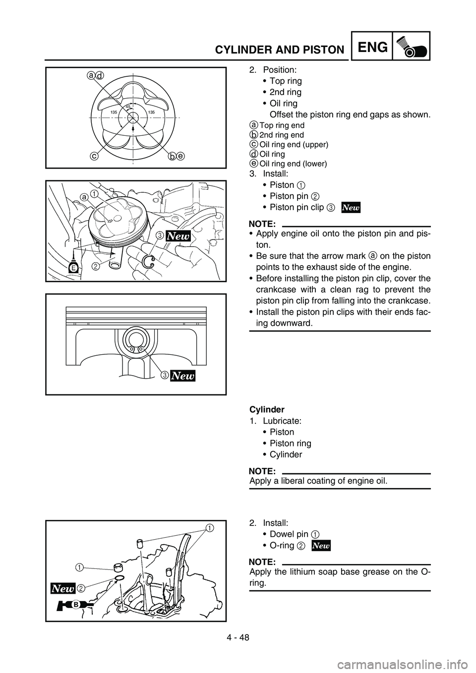
2. Position:
Top ring
2nd ring
Oil ring
Offset the piston ring end gaps as shown.
a
Top ring end
b2nd ring end
cOil ring end (upper)
dOil ring
eOil ring end (lower)
3. Install:
Piston 1
Piston pin 2
Piston pin clip 3
NOTE:
Apply engine oil onto the piston pin and pis-
ton.
Be sure that the arrow mark a on the piston
points to the exhaust side of the engine.
Before installing the piston pin clip, cover the
crankcase with a clean rag to prevent the
piston pin clip from falling into the crankcase.
Install the piston pin clips with their ends fac-
ing downward.
45
135 135
a
b ced
3
Cylinder
1. Lubricate:
Piston
Piston ring
Cylinder
NOTE:
Apply a liberal coating of engine oil.
2. Install:
Dowel pin 1
O-ring 2
NOTE:
Apply the lithium soap base grease on the O-
ring.
Page 354 of 674
4 - 50
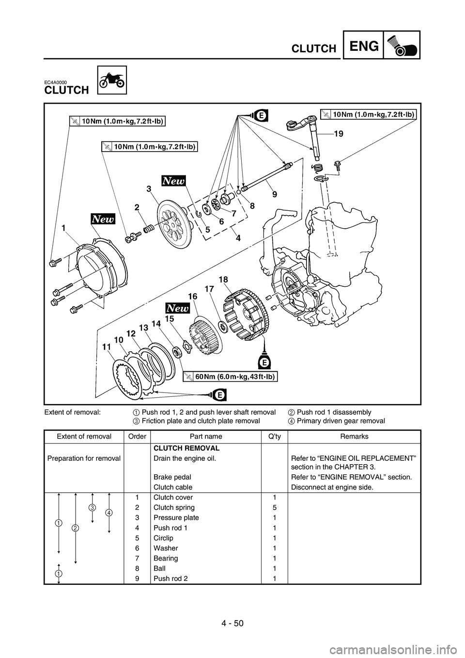
ENGCLUTCH
EC4A0000
CLUTCH
Extent of removal:
1 Push rod 1, 2 and push lever shaft removal
2 Push rod 1 disassembly
3 Friction plate and clutch plate removal
4 Primary driven gear removal
Extent of removal Order Part name Q’ty Remarks
CLUTCH REMOVAL
Preparation for removal Drain the engine oil. Refer to “ENGINE OIL REPLACEMENT”
section in the CHAPTER 3.
Brake pedal Refer to “ENGINE REMOVAL” section.
Clutch cable Disconnect at engine side.
1 Clutch cover 1
2 Clutch spring 5
3 Pressure plate 1
4 Push rod 1 1
5 Circlip 1
6 Washer 1
7 Bearing 1
8Ball 1
9 Push rod 2 1
1
4
1
3
2