fuel YAMAHA YZ250F 2008 User Guide
[x] Cancel search | Manufacturer: YAMAHA, Model Year: 2008, Model line: YZ250F, Model: YAMAHA YZ250F 2008Pages: 192, PDF Size: 7.03 MB
Page 23 of 192

2-1
GENERAL SPECIFICATIONS
SPECIFICATIONS
GENERAL SPECIFICATIONS
Model name:YZ250FX (USA, CDN, AUS, NZ)
YZ250F (EUROPE, ZA)
Model code number: 5XCL (USA,CDN)
5XCM (EUROPE)
5XCP (AUS, NZ, ZA)
Dimensions: USA, CDN, ZA, AUS, NZEUROPE
Overall length 2,162 mm (85.12 in) 2,165 mm (85.24 in)
Overall width 825 mm (32.48 in)
←
Overall height1,300 mm (51.18 in)←
Seat height 985 mm (38.78 in)997 mm (39.25 in)
Wheelbase 1,469 mm (57.83 in)
←
Minimum ground clearance370 mm (14.57 in)372 mm (14.65 in)
Dry weight: Without oil and fuel 92.7 kg (204 lb)
Engine: Engine type Liquid cooled 4-stroke, DOHC
Cylinder arrangement Single cylinder, forward inclined
Displacement 249 cm
3 (8.76 Imp oz, 8.42 US oz)
Bore × stroke 77.0 × 53.6 mm (3.03 × 2.11 in)
Compression ratio 13.5 : 1
Starting system Kickstarter
Lubrication system: Dry sump
Oil type or grade: Engine oil (For USA and CDN)
Yamalube 4, SAE10W30 or SAE20W40
Yamalube 4-R, SAE10W50
API service SG type or higher,
JASO standard MA
(Except for USA and CDN)
SAE10W30, SAE10W40, SAE15W40,
SAE20W40 or SAE20W50
API service SG type or higher,
JASO standard MA
Oil capacity: Engine oilPeriodic oil change 1.05 L (0.92 Imp qt, 1.11 US qt)
With oil filter replacement 1.15 L (1.01 Imp qt, 1.22 US qt)
Total amount 1.30 L (1.14 Imp qt, 1.37 US qt)
Coolant capacity (including all routes): 0.99 L (0.87 Imp qt, 1.05 US qt)
Air filter: Wet type element
2
Page 24 of 192
2-2
GENERAL SPECIFICATIONS
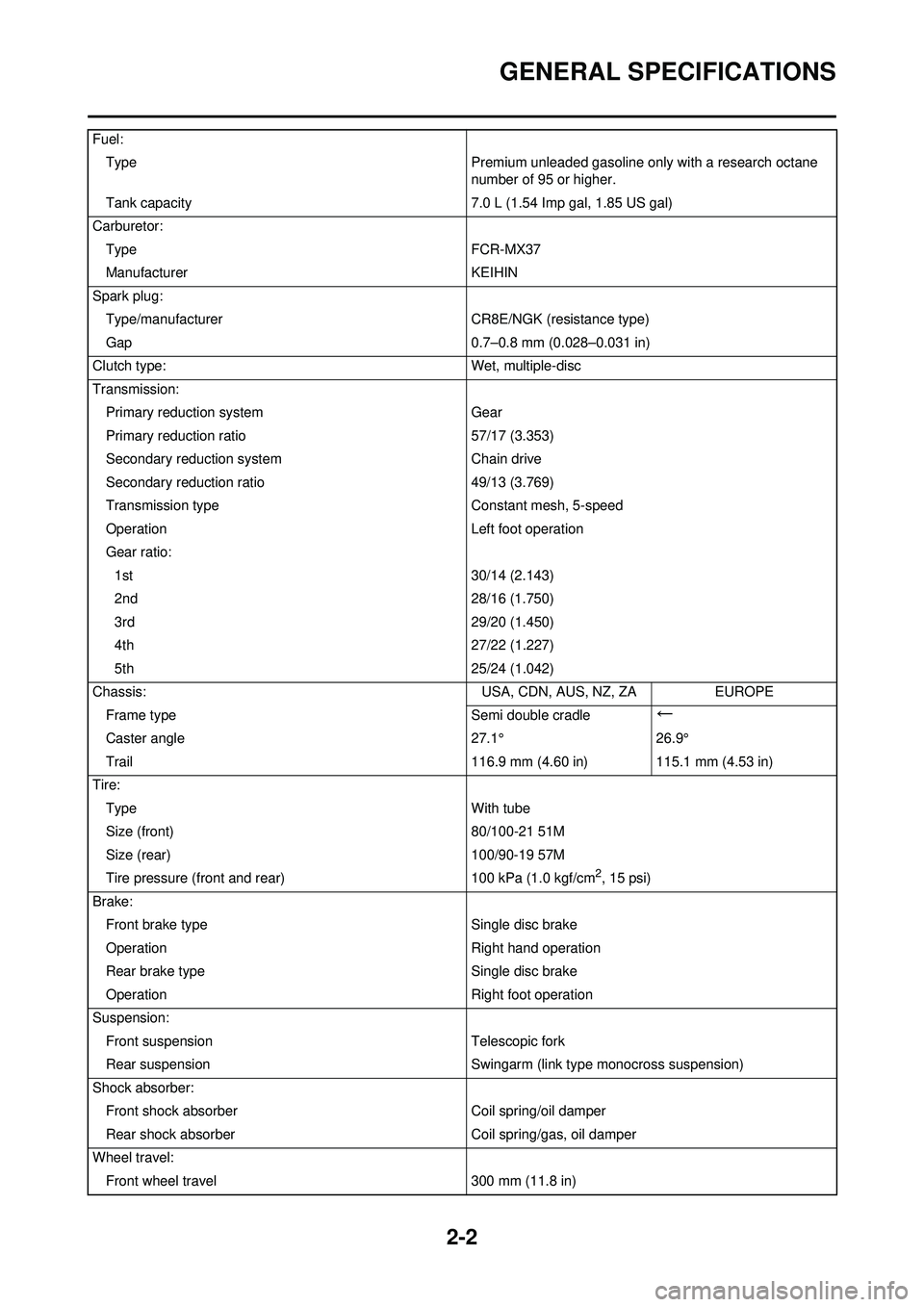
Fuel:Type Premium unleaded gasoline only with a research octane
number of 95 or higher.
Tank capacity 7.0 L (1.54 Imp gal, 1.85 US gal)
Carburetor: Type FCR-MX37
Manufacturer KEIHIN
Spark plug: Type/manufacturer CR8E/NGK (resistance type)
Gap 0.7–0.8 mm (0.028–0.031 in)
Clutch type: Wet, multiple-disc
Transmission: Primary reduction system Gear
Primary reduction ratio 57/17 (3.353)
Secondary reduction system Chain drive
Secondary reduction ratio 49/13 (3.769)
Transmission type Constant mesh, 5-speed
Operation Left foot operation
Gear ratio: 1st 30/14 (2.143)
2nd 28/16 (1.750)
3rd 29/20 (1.450)
4th 27/22 (1.227)
5th 25/24 (1.042)
Chassis: USA, CDN, AUS, NZ, ZAEUROPE
Frame type Semi double cradle
←
Caster angle27.1°26.9°
Trail 116.9 mm (4.60 in) 115.1 mm (4.53 in)
Tire: Type With tube
Size (front) 80/100-21 51M
Size (rear) 100/90-19 57M
Tire pressure (front and rear) 100 kPa (1.0 kgf/cm
2, 15 psi)
Brake: Front brake type Single disc brake
Operation Right hand operation
Rear brake type Single disc brake
Operation Right foot operation
Suspension: Front suspension Telescopic fork
Rear suspension Swingarm (link type monocross suspension)
Shock absorber: Front shock absorber Coil spring/oil damper
Rear shock absorber Coil spring/gas, oil damper
Wheel travel: Front wheel travel 300 mm (11.8 in)
Page 35 of 192
2-13
TIGHTENING TORQUES
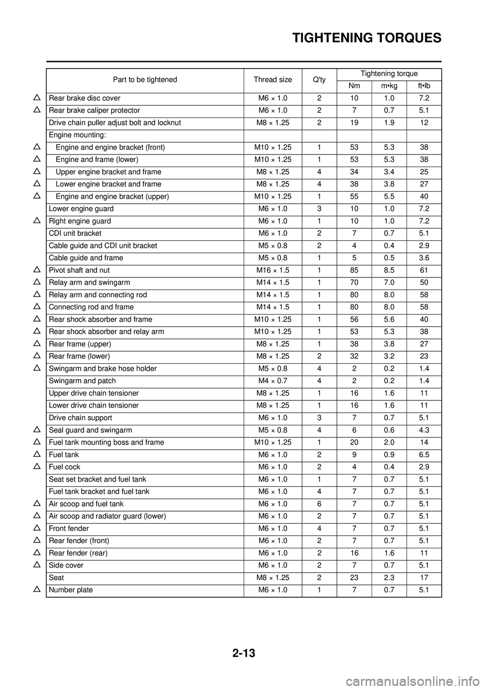
△Rear brake disc coverM6 × 1.0 2 10 1.0 7.2
△Rear brake caliper protector M6 × 1.0 2 7 0.7 5.1
Drive chain puller adjust bolt and locknut M8 × 1.25 2 19 1.9 12
Engine mounting:
△Engine and engine bracket (front) M10 × 1.25 1 53 5.3 38
△Engine and frame (lower) M10 × 1.25 1 53 5.3 38
△Upper engine bracket and frame M8 × 1.25 4 34 3.4 25
△Lower engine bracket and frameM8 × 1.25 4 38 3.8 27
△Engine and engine bracket (upper)M10 × 1.25 1 55 5.5 40
Lower engine guard M6 × 1.0 3 10 1.0 7.2
△Right engine guardM6 × 1.0 1 10 1.0 7.2
CDI unit bracket M6 × 1.0 2 7 0.7 5.1
Cable guide and CDI unit bracket M5 × 0.8 2 4 0.4 2.9
Cable guide and frame M5 × 0.8 1 5 0.5 3.6
△Pivot shaft and nutM16 × 1.5 1 85 8.5 61
△Relay arm and swingarmM14 × 1.5 1 70 7.0 50
△Relay arm and connecting rod M14 × 1.5 1 80 8.0 58
△Connecting rod and frame M14 × 1.5 1 80 8.0 58
△Rear shock absorber and frameM10 × 1.25 1 56 5.6 40
△Rear shock absorber and relay armM10 × 1.25 1 53 5.3 38
△Rear frame (upper) M8 × 1.25 1 38 3.8 27
△Rear frame (lower) M8 × 1.25 2 32 3.2 23
△Swingarm and brake hose holder M5 × 0.8 4 2 0.2 1.4
Swingarm and patch M4 × 0.7 4 2 0.2 1.4
Upper drive chain tensioner M8 × 1.25 1 16 1.6 11
Lower drive chain tensioner M8 × 1.25 1 16 1.6 11
Drive chain support M6 × 1.0 3 7 0.7 5.1
△Seal guard and swingarmM5 × 0.8 4 6 0.6 4.3
△Fuel tank mounting boss and frameM10 × 1.25 1 20 2.0 14
△Fuel tank M6 × 1.0 2 9 0.9 6.5
△Fuel cockM6 × 1.0 2 4 0.4 2.9
Seat set bracket and fuel tank M6 × 1.0 1 7 0.7 5.1
Fuel tank bracket and fuel tank M6 × 1.0 4 7 0.7 5.1
△Air scoop and fuel tankM6 × 1.0 6 7 0.7 5.1
△Air scoop and radiator guard (lower) M6 × 1.0 2 7 0.7 5.1
△Front fenderM6 × 1.0 4 7 0.7 5.1
△Rear fender (front) M6 × 1.0 2 7 0.7 5.1
△Rear fender (rear) M6 × 1.0 2 16 1.6 11
△Side coverM6 × 1.0 2 7 0.7 5.1
Seat M8 × 1.25 2 23 2.3 17
△Number plate M6 × 1.0 1 7 0.7 5.1
Part to be tightened
Thread size Q'tyTightening torque
Nm m•kg ft•lb
Page 40 of 192

2-18
CABLE ROUTING DIAGRAM
CABLE ROUTING DIAGRAM
1. Fuel tank breather hose
2. Radiator hose 1
3. Connector cover
4. Cylinder head breather hose
5. Radiator hose 4
6. Clutch cable
7. Throttle position sensor lead
8. Carburetor breather hose
9. Upper engine bracket10. Hot starter cable
11. Fuel hose
12. Carburetor overflow hose
A. Insert the end of the fuel tank
breather hose into the hole in
the steering stem.
B. Install the connector cover so that it does not come in between
the radiator hose 1 and radiator. C. Aligh the paint mark on the cylin-
der head breather hose with the
front end of the hose guide.
D. Pass the cylinder head breather hose on the outside of the radia-
tor hose 1 and then between the
radiator 4 and frame.
E. Pass the clutch cable through
the cable guide.
Page 41 of 192

2-19
CABLE ROUTING DIAGRAM
F. Pass the clutch cable in front of the radiator mounting boss.
G. Pass the fuel hose between the hot starter cable and throttle po-
sition sensor lead.
H. Pass the carburetor breater hos- es so that they are not pinched
between the upper engine
bracket and carburetor.
I. Pass the carburetor breather
hoses and overflow hose so that
all there hoses do not contact
the rear shock absorber.
Page 49 of 192

3-3
MAINTENANCE INTERVALS
OIL STRAINERClean
●
FRAMEClean and inspect
●●
FUEL TANK, COCKClean and inspect
●●
BRAKESAdjust lever position and pedal
height
●●
Lubricate pivot point●●
Check brake disc surface●●
Check fluid level and leakage●●
Retighten brake disc bolts, cali-
per bolts, master cylinder bolts
and union bolts●●
Replace pads●
Replace brake fluid●Every one year
FRONT FORKS Inspect and adjust
●●
Replace oil●●Suspension oil "S1"
Replace oil seal
●
FRONT FORK OIL SEAL AND
DUST SEAL Clean and lube
●●Lithium base grease
PROTECTOR GUIDE Replace
●
REAR SHOCK ABSORBERInspect and adjust
●●
Lube●
(After rain
ride)
●Molybdenum disulfide grease
Replace spring seat
●Every one year
Retighten
●●
DRIVE CHAIN GUIDE AND
ROLLERS Inspect
●●
SWINGARMInspect, lube and retighten
●●Molybdenum disulfide grease
RELAY ARM, CONNECTING
ROD Inspect, lube and retighten
●●Molybdenum disulfide grease
STEERING HEAD Inspect free play and retighten
●●
Clean and lube●Lithium base grease
Replace bearing
●
Item After
break-
in Every
race
Every third
(or 500 km) Every
fifth (or 1,000 km)
As re-
quired Remarks
Page 51 of 192
3-5
PRE-OPERATION INSPECTION AND MAINTENANCE
PRE-OPERATION INSPECTION AND MAINTENANCE
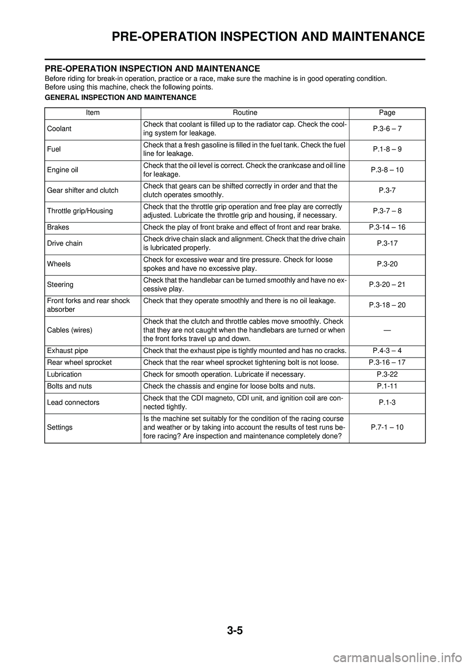
Before riding for break-in operation, practice or a race, make sure the machine is in good operating condition.
Before using this machine, check the following points.
GENERAL INSPECTION AND MAINTENANCEItem RoutinePage
Coolant Check that coolant is filled up to the radiator cap. Check the cool-
ing system for leakage. P.3-6 – 7
Fuel Check that a fresh gasoline is filled in the fuel tank. Check the fuel
line for leakage. P.1-8 – 9
Engine oil Check that the oil level is correct. Check the crankcase and oil line
for leakage. P.3-8 – 10
Gear shifter and clutch Check that gears can be shifted correctly in order and that the
clutch operates smoothly. P.3-7
Throttle grip/Housing Check that the throttle grip operation and free play are correctly
adjusted. Lubricate the throttle grip and housing, if necessary. P.3-7 – 8
Brakes Check the play of front brake and effect of front and rear brake. P.3-14 – 16
Drive chain Check drive chain slack and alignment. Check that the drive chain
is lubricated properly. P.3-17
Wheels Check for excessive wear and tire pressure. Check for loose
spokes and have no excessive play. P.3-20
Steering Check that the handlebar can be turned smoothly and have no ex-
cessive play. P.3-20 – 21
Front forks and rear shock
absorber Check that they operate smoothly and there is no oil leakage.
P.3-18 – 20
Cables (wires) Check that the clutch and throttle cables move smoothly. Check
that they are not caught when the handlebars are turned or when
the front forks travel up and down.
—
Exhaust pipe Check that the exhaust pipe is tightly mounted and has no cracks. P.4-3 – 4
Rear wheel sprocket Check that the rear wheel sprocket tightening bolt is not loose. P.3-16 – 17
Lubrication Check for smooth operation. Lubricate if necessary. P.3-22
Bolts and nuts Check the chassis and engine for loose bolts and nuts. P.1-11
Lead connectors Check that the CDI magneto, CDI unit, and ignition coil are con-
nected tightly. P.1-3
Settings Is the machine set suitably for the condition of the racing course
and weather or by taking into account the results of test runs be-
fore racing? Are inspection and maintenance completely done?
P.7-1 – 10
Page 56 of 192

3-10
ENGINE
• Oil hose clamp
9. Install: • Copper washer
• Oil filter element drain bolt
• Crankcase oil drain bolt
• Oil tank drain bolt
• Lower engine guard
10. Fill: • Engine oil
11. Check: • Oil leakage
12. Install: • Oil filler cap
• Washer (oil tank) • Bolt (oil tank)
13. Check: • Engine oil level
CHECKING THE OIL PRESSURE
1. Check: • Oil pressure
Checking steps:
a. Slightly loosen the oil pressure check bolt "1".
b. Start the engine and keep it idling until oil starts to seep from the oil
pressure check bolt. If no oil
comes out after one minute, turn
the engine off so it will not seize.
c. Check oil passages and oil pump for damage or leakage.
d. Start the engine after solving the
problem(s) and recheck the oil
pressure.
e. Tighten the oil pressure check
bolt.
ADJUSTING THE PILOT SCREW
1. Adjust:• Pilot screw "1"
Adjustment steps:
To optimize the fuel flow at a smaller
throttle opening, each machine's pilot
screw has been individually set at the
factory. Before adjusting the pilot
screw, turn it in fully and count the
number of turns. Record this number
as the factory-set number of turns
out.
a. Turn in the pilot screw until it is lightly seated.
b. Turn out the pilot screw by the factory-set number of turns.
ADJUSTING THE ENGINE IDLING
SPEED
1. Start the engine and thoroughly warm it up.
2. Adjust: • Engine idling speed
Adjustment steps:
a. Adjust the pilot screw. Refer to "ADJUSTING THE PI-
LOT SCREW" section.
b. Turn the throttle stop screw "1"
until the specified engine idling
speed.
Using a digital engine tachometer for
idle speed adjustment, detect the en-
gine idling speed by bringing the
sensing element "c" of the engine ta-
chometer close to the ignition coil "2".
Oil hose clamp:2 Nm (0.2 m•kg, 1.4
ft•lb)
Oil filter element drain
bolt: 10 Nm (1.0 m•kg, 7.2
ft•lb)
Crankcase oil drain bolt: 20 Nm (2.0 m•kg, 14
ft•lb)
Oil tank drain bolt: 18 Nm (1.8 m•kg, 13
ft•lb)
Lower engine guard: 10 Nm (1.0 m•kg, 7.2
ft•lb)
Oil quantity: Periodic oil change:1.05 L (0.92 Imp qt,
1.11 US qt)
With oil filter replace-
ment: 1.15 L (1.01 Imp qt,
1.22 US qt)
Total amount:
1.30 L (1.14 Imp qt,
1.37 US qt)Bolt (oil tank): 7 Nm (0.7 m•kg, 5.1
ft•lb)
Oil pressure check bolt: 10 Nm (1.0 m•kg, 7.2
ft•lb)
Pilot screw (example): 2-3/8 turns out
To increase idle speed→Turn the
throttle stop screw "1" in "a".
To decrease idle speed
→Turn
the throttle stop screw "1" out
"b".
Engine idling speed:1,900–2,100 r/min
Page 57 of 192
3-11
ENGINE
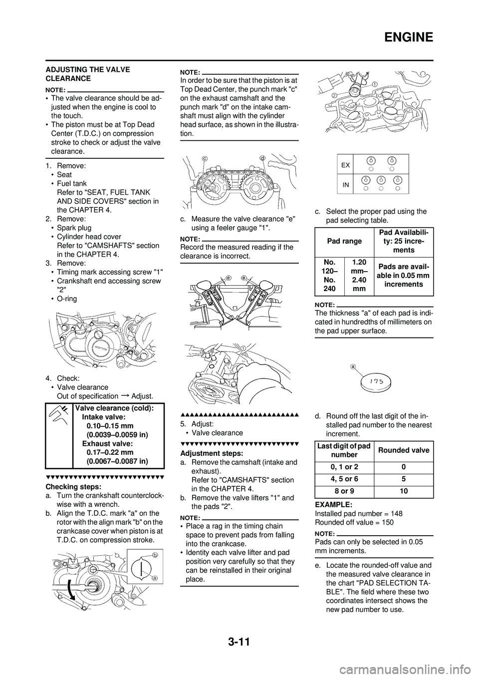
ADJUSTING THE VALVE
CLEARANCE
•The valve clearance should be ad-
justed when the engine is cool to
the touch.
• The piston must be at Top Dead Center (T.D.C.) on compression
stroke to check or adjust the valve
clearance.
1. Remove:• Seat
• Fuel tankRefer to "SEAT, FUEL TANK
AND SIDE COVERS" section in
the CHAPTER 4.
2. Remove: • Spark plug
• Cylinder head coverRefer to "CAMSHAFTS" section
in the CHAPTER 4.
3. Remove:
• Timing mark accessing screw "1"
• Crankshaft end accessing screw "2"
• O-ring
4. Check: • Valve clearance
Out of specification
→Adjust.
Checking steps:
a. Turn the crankshaft counterclock- wise with a wrench.
b. Align the T.D.C. mark "a" on the rotor with the align mark "b" on the
crankcase cover when piston is at
T.D.C. on compression stroke.
In order to be sure that the piston is at
Top Dead Center, the punch mark "c"
on the exhaust camshaft and the
punch mark "d" on the intake cam-
shaft must align with the cylinder
head surface, as shown in the illustra-
tion.
c. Measure the valve clearance "e"
using a feeler gauge "1".
Record the measured reading if the
clearance is incorrect.
5. Adjust:• Valve clearance
Adjustment steps:
a. Remove the camshaft (intake and exhaust).
Refer to "CAMSHAFTS" section
in the CHAPTER 4.
b. Remove the valve lifters "1" and the pads "2".
•Place a rag in the timing chain
space to prevent pads from falling
into the crankcase.
• Identity each valve lifter and pad
position very carefully so that they
can be reinstalled in their original
place.
c. Select the proper pad using the pad selecting table.
The thickness "a" of each pad is indi-
cated in hundredths of millimeters on
the pad upper surface.
d. Round off the last digit of the in-stalled pad number to the nearest
increment.
EXAMPLE:
Installed pad number = 148
Rounded off value = 150
Pads can only be selected in 0.05
mm increments.
e. Locate the rounded-off value and the measured valve clearance in
the chart "PAD SELECTION TA-
BLE". The field where these two
coordinates intersect shows the
new pad number to use.
Valve clearance (cold):
Intake valve:0.10–0.15 mm
(0.0039–0.0059 in)
Exhaust valve: 0.17–0.22 mm
(0.0067–0.0087 in)
Pad range Pad Availabili-
ty: 25 incre-
ments
No.
120– No.
240 1.20
mm– 2.40 mm Pads are avail-
able in 0.05 mm increments
Last digit of pad number Rounded valve
0, 1 or 2 0
4, 5 or 6 5
8 or 9 10
Page 67 of 192
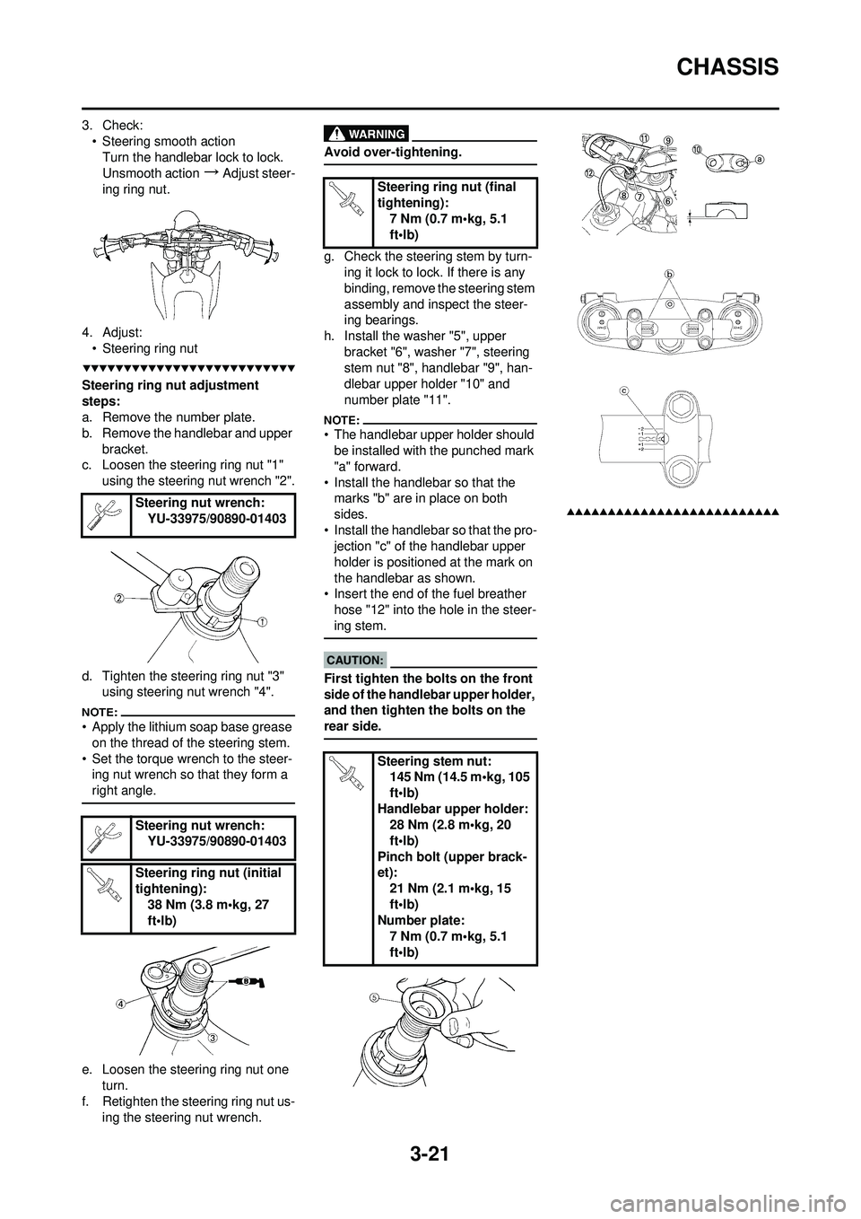
3-21
CHASSIS
3. Check:• Steering smooth actionTurn the handlebar lock to lock.
Unsmooth action
→Adjust steer-
ing ring nut.
4. Adjust: • Steering ring nut
Steering ring nut adjustment
steps:
a. Remove the number plate.
b. Remove the handlebar and upper
bracket.
c. Loosen the steering ring nut "1"
using the steering nut wrench "2".
d. Tighten the steering ring nut "3" using steering nut wrench "4".
• Apply the lithium soap base grease
on the thread of the steering stem.
• Set the torque wrench to the steer- ing nut wrench so that they form a
right angle.
e. Loosen the steering ring nut one
turn.
f. Retighten the steering ring nut us- ing the steering nut wrench.
Avoid over-tightening.
g. Check the steering stem by turn-ing it lock to lock. If there is any
binding, remove the steering stem
assembly and inspect the steer-
ing bearings.
h. Install the washer "5", upper bracket "6", washer "7", steering
stem nut "8", handlebar "9", han-
dlebar upper holder "10" and
number plate "11".
• The handlebar upper holder should be installed with the punched mark
"a" forward.
• Install the handlebar so that the marks "b" are in place on both
sides.
• Install the handlebar so that the pro- jection "c" of the handlebar upper
holder is positioned at the mark on
the handlebar as shown.
• Insert the end of the fuel breather
hose "12" into the hole in the steer-
ing stem.
First tighten the bolts on the front
side of the handlebar upper holder,
and then tighten the bolts on the
rear side.
Steering nut wrench: YU-33975/90890-01403
Steering nut wrench: YU-33975/90890-01403
Steering ring nut (initial
tightening): 38 Nm (3.8 m•kg, 27
ft•lb)
Steering ring nut (final
tightening):7 Nm (0.7 m•kg, 5.1
ft•lb)
Steering stem nut: 145 Nm (14.5 m•kg, 105
ft•lb)
Handlebar upper holder: 28 Nm (2.8 m•kg, 20
ft•lb)
Pinch bolt (upper brack-
et): 21 Nm (2.1 m•kg, 15
ft•lb)
Number plate:
7 Nm (0.7 m•kg, 5.1
ft•lb)