ignition YAMAHA YZ250F 2008 Owners Manual
[x] Cancel search | Manufacturer: YAMAHA, Model Year: 2008, Model line: YZ250F, Model: YAMAHA YZ250F 2008Pages: 192, PDF Size: 7.03 MB
Page 10 of 192
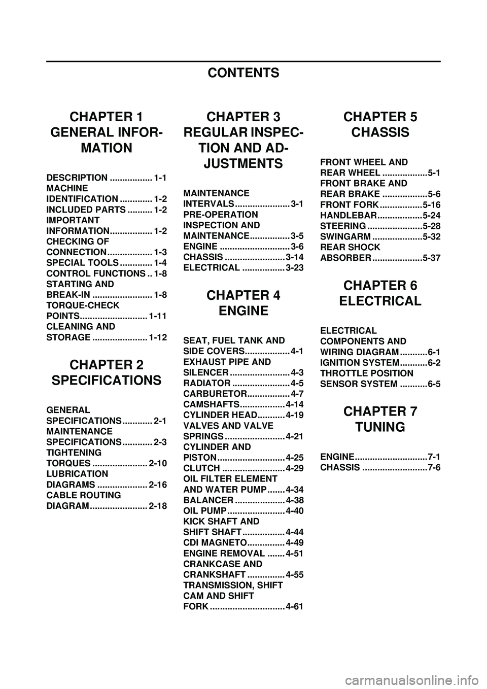
CONTENTS
CHAPTER 1
GENERAL INFOR-
MATION
DESCRIPTION ................. 1-1
MACHINE
IDENTIFICATION ............. 1-2
INCLUDED PARTS .......... 1-2
IMPORTANT
INFORMATION................. 1-2
CHECKING OF
CONNECTION .................. 1-3
SPECIAL TOOLS ............. 1-4
CONTROL FUNCTIONS .. 1-8
STARTING AND
BREAK-IN ........................ 1-8
TORQUE-CHECK
POINTS........................... 1-11
CLEANING AND
STORAGE ...................... 1-12
CHAPTER 2
SPECIFICATIONS
GENERAL
SPECIFICATIONS ............ 2-1
MAINTENANCE
SPECIFICATIONS ............ 2-3
TIGHTENING
TORQUES ...................... 2-10
LUBRICATION
DIAGRAMS .................... 2-16
CABLE ROUTING
DIAGRAM ....................... 2-18
CHAPTER 3
REGULAR INSPEC-
TION AND AD-JUSTMENTS
MAINTENANCE
INTERVALS ...................... 3-1
PRE-OPERATION
INSPECTION AND
MAINTENANCE................ 3-5
ENGINE ............................ 3-6
CHASSIS ........................ 3-14
ELECTRICAL ................. 3-23
CHAPTER 4 ENGINE
SEAT, FUEL TANK AND
SIDE COVERS.................. 4-1
EXHAUST PIPE AND
SILENCER ........................ 4-3
RADIATOR ....................... 4-5
CARBURETOR................. 4-7
CAMSHAFTS.................. 4-14
CYLINDER HEAD........... 4-19
VALVES AND VALVE
SPRINGS ........................ 4-21
CYLINDER AND
PISTON ........................... 4-25
CLUTCH ......................... 4-29
OIL FILTER ELEMENT
AND WATER PUMP ....... 4-34
BALANCER .................... 4-38
OIL PUMP ....................... 4-40
KICK SHAFT AND
SHIFT SHAFT ................. 4-44
CDI MAGNETO............... 4-49
ENGINE REMOVAL ....... 4-51
CRANKCASE AND
CRANKSHAFT ............... 4-55
TRANSMISSION, SHIFT
CAM AND SHIFT
FORK .............................. 4-61
CHAPTER 5CHASSIS
FRONT WHEEL AND
REAR WHEEL ..................5-1
FRONT BRAKE AND
REAR BRAKE ..................5-6
FRONT FORK ................. 5-16
HANDLEBAR..................5-24
STEERING ......................5-28
SWINGARM ....................5-32
REAR SHOCK
ABSORBER ....................5-37
CHAPTER 6
ELECTRICAL
ELECTRICAL
COMPONENTS AND
WIRING DIAGRAM ...........6-1
IGNITION SYSTEM...........6-2
THROTTLE POSITION
SENSOR SYSTEM ...........6-5
CHAPTER 7
TUNING
ENGINE.............................7-1
CHASSIS ..........................7-6
Page 16 of 192

1-6
SPECIAL TOOLS
Timing light
YM-33277-A, 90890-03141 This tool is necessary for checking
ignition timing.
Valve spring compressor
YM-4019, 90890-04019 This tool is needed to remove and
install the valve assemblies.
Clutch holding tool
YM-91042, 90890-04086 This tool is used to hold the clutch
when removing or installing the
clutch boss securing nut.
Valve guide remover
Intake 4.0 mm (0.16 in)
Exhaust 4.5 mm (0.18 in)
YM-4111, 90890-04111
YM-4116, 90890-04116 This tool is needed to remove and
install the valve guide.
Valve guide installer
Intake 4.0 mm (0.16 in)
Exhaust 4.5 mm (0.18 in)
YM-4112, 90890-04112
YM-4117, 90890-04117 This tool is needed to install the
valve guide.
Valve guide reamer
Intake 4.0 mm (0.16 in)
Exhaust 4.5 mm (0.18 in)
YM-4113, 90890-04113
YM-4118, 90890-04118 This tool is needed to rebore the
new valve guide.
Tool name/Part number How to use Illustration
Page 17 of 192

1-7
SPECIAL TOOLS
Dynamic spark tester
YM-34487
Ignition checker
90890-06754This instrument is necessary for
checking the ignition system compo-
nents.
YAMAHA Bond No. 1215 (ThreeB-
ond
® No. 1215)
90890-85505 This sealant (Bond) is used for
crankcase mating surface, etc.
Tool name/Part number How to use Illustration
Page 25 of 192

2-3
MAINTENANCE SPECIFICATIONS
MAINTENANCE SPECIFICATIONS
ENGINERear wheel travel
306 mm (12.0 in)
Electrical: Ignition system CDI magneto
ItemStandardLimit
Cylinder head: Warp limit ----0.05 mm (0.002
in)
Cylinder: Bore size 77.00–77.01 mm (3.0315–3.0319 in) ----
Out of round limit ----0.05 mm (0.002
in)
Camshaft: Drive method Chain drive (Left)----
Camshaft cap inside diameter 22.000–22.021 mm (0.8661–0.8670 in) ----
Camshaft outside diameter 21.959–21.972 mm (0.8645–0.8650 in) ----
Shaft-to-cap clearance 0.028–0.062 mm (0.0011–0.0024 in) 0.08 mm (0.003
in)
Cam dimensions
Intake "A" 30.246–30.346 mm (1.1908–1.1947 in) 30.146 mm
(1.1869 in)
Intake "B" 22.45–22.55 mm (0.8839–0.8878 in) 22.35 mm
(0.8799 in)
Exhaust "A" 30.399–30.499 mm (1.1968–1.2007 in) 30.299 mm
(1.1929 in)
Exhaust "B" 22.45–22.55 mm (0.8839–0.8878 in) 22.35 mm
(0.8799 in)
Camshaft runout limit ----0.03 mm
(0.0012 in)
Timing chain: Timing chain type/No. of links 92RH2010-114M/114----
Timing chain adjustment method Automatic----
Page 31 of 192
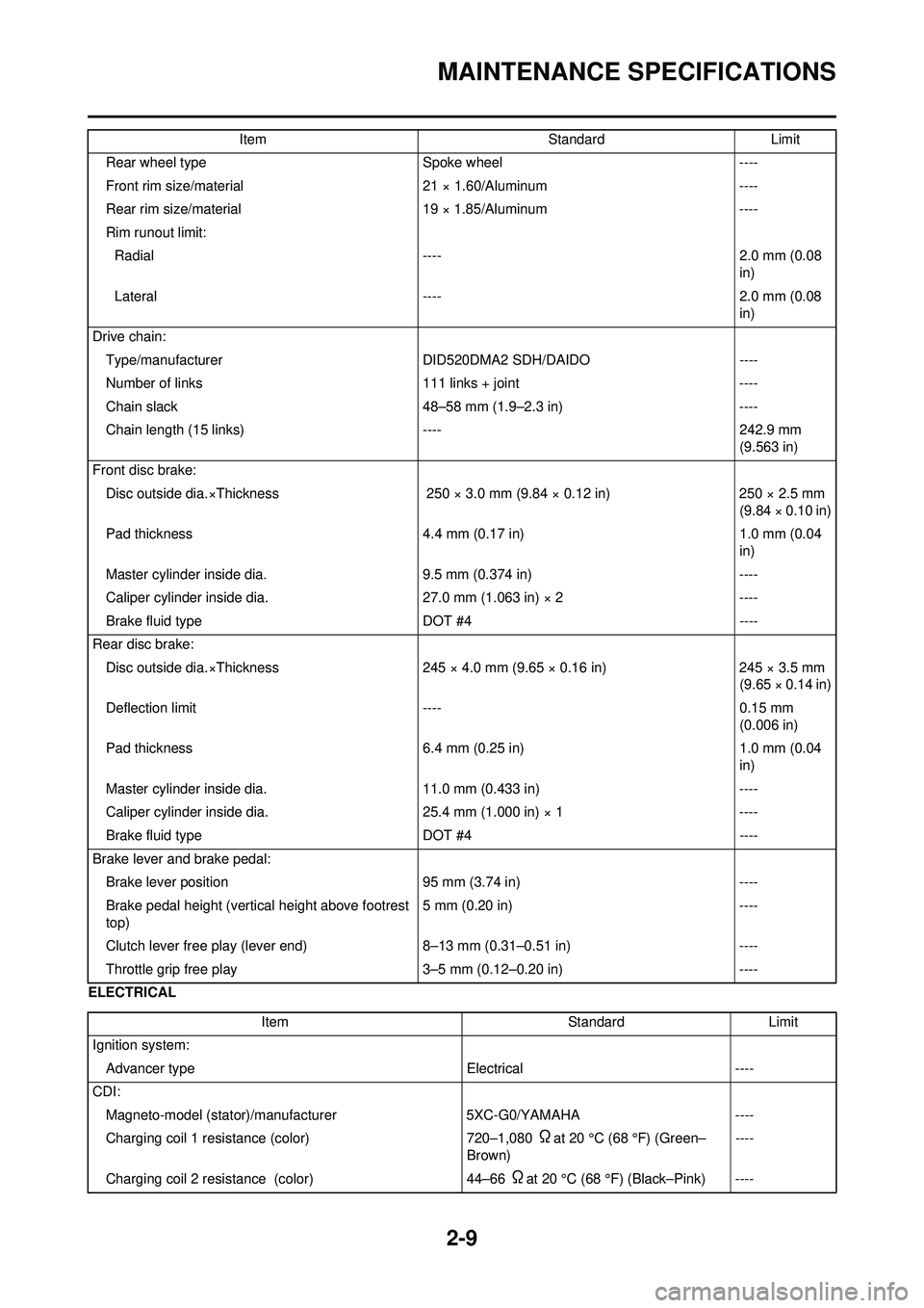
2-9
MAINTENANCE SPECIFICATIONS
ELECTRICALRear wheel type
Spoke wheel----
Front rim size/material 21 × 1.60/Aluminum----
Rear rim size/material 19 × 1.85/Aluminum----
Rim runout limit: Radial ---- 2.0 mm (0.08
in)
Lateral ---- 2.0 mm (0.08
in)
Drive chain: Type/manufacturer DID520DMA2 SDH/DAIDO ----
Number of links 111 links + joint----
Chain slack 48–58 mm (1.9–2.3 in)----
Chain length (15 links) ----242.9 mm
(9.563 in)
Front disc brake: Disc outside dia.×Thickness 250 × 3.0 mm (9.84 × 0.12 in)250 × 2.5 mm
(9.84 × 0.10 in)
Pad thickness 4.4 mm (0.17 in)1.0 mm (0.04
in)
Master cylinder inside dia. 9.5 mm (0.374 in)----
Caliper cylinder inside dia. 27.0 mm (1.063 in) × 2----
Brake fluid type DOT #4----
Rear disc brake: Disc outside dia.×Thickness 245 × 4.0 mm (9.65 × 0.16 in)245 × 3.5 mm
(9.65 × 0.14 in)
Deflection limit ----0.15 mm
(0.006 in)
Pad thickness 6.4 mm (0.25 in)1.0 mm (0.04
in)
Master cylinder inside dia. 11.0 mm (0.433 in)----
Caliper cylinder inside dia. 25.4 mm (1.000 in) × 1----
Brake fluid type DOT #4----
Brake lever and brake pedal: Brake lever position 95 mm (3.74 in)----
Brake pedal height (vertical height above footrest
top) 5 mm (0.20 in)
----
Clutch lever free play (lever end) 8–13 mm (0.31–0.51 in)----
Throttle grip free play 3–5 mm (0.12–0.20 in)----
Item
StandardLimit
Item StandardLimit
Ignition system: Advancer type Electrical----
CDI: Magneto-model (stator)/manufacturer 5XC-G0/YAMAHA----
Charging coil 1 resistance (color) 720–1,080
Ωat 20 °C (68 °F) (Green–
Brown) ----
Charging coil 2 resistance (color) 44–66
Ωat 20 °C (68 °F) (Black–Pink) ----
Page 32 of 192
2-10
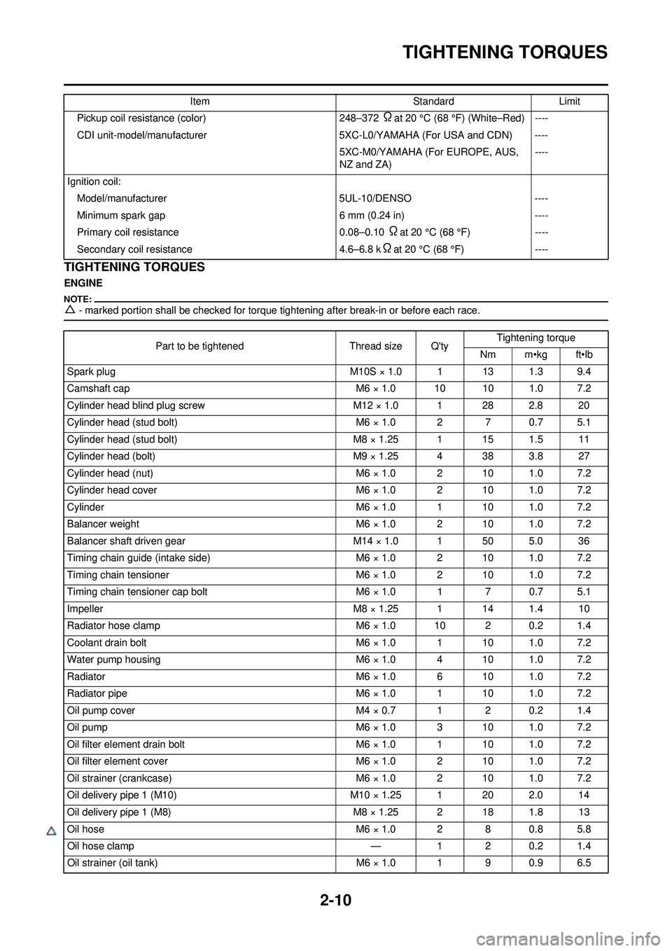
TIGHTENING TORQUES
TIGHTENING TORQUES
ENGINE
△- marked portion shall be checked for torque tightening after break-in or before each race.
Pickup coil resistance (color)248–372 Ωat 20 °C (68 °F) (White–Red) ----
CDI unit-model/manufacturer 5XC-L0/YAMAHA (For USA and CDN) ----
5XC-M0/YAMAHA (For EUROPE, AUS,
NZ and ZA) ----
Ignition coil: Model/manufacturer 5UL-10/DENSO----
Minimum spark gap 6 mm (0.24 in)----
Primary coil resistance 0.08–0.10
Ωat 20 °C (68 °F)----
Secondary coil resistance 4.6–6.8 k
Ωat 20 °C (68 °F)----
Item
StandardLimit
Part to be tightened Thread size Q'tyTightening torque
Nm m•kg ft•lb
Spark plug M10S × 1.0 1 13 1.3 9.4
Camshaft cap M6 × 1.0 10 10 1.0 7.2
Cylinder head blind plug screw M12 × 1.0 1 28 2.8 20
Cylinder head (stud bolt) M6 × 1.0 2 7 0.7 5.1
Cylinder head (stud bolt) M8 × 1.25 1 15 1.5 11
Cylinder head (bolt) M9 × 1.25 4 38 3.8 27
Cylinder head (nut) M6 × 1.0 2 10 1.0 7.2
Cylinder head cover M6 × 1.0 2 10 1.0 7.2
Cylinder M6 × 1.0 1 10 1.0 7.2
Balancer weight M6 × 1.0 2 10 1.0 7.2
Balancer shaft driven gear M14 × 1.0 1 50 5.0 36
Timing chain guide (intake side) M6 × 1.0 2 10 1.0 7.2
Timing chain tensioner M6 × 1.0 2 10 1.0 7.2
Timing chain tensioner cap bolt M6 × 1.0 1 7 0.7 5.1
Impeller M8 × 1.25 1 14 1.4 10
Radiator hose clamp M6 × 1.0 10 2 0.2 1.4
Coolant drain bolt M6 × 1.0 1 10 1.0 7.2
Water pump housing M6 × 1.0 4 10 1.0 7.2
Radiator M6 × 1.0 6 10 1.0 7.2
Radiator pipe M6 × 1.0 1 10 1.0 7.2
Oil pump cover M4 × 0.7 1 2 0.2 1.4
Oil pump M6 × 1.0 3 10 1.0 7.2
Oil filter element drain bolt M6 × 1.0 1 10 1.0 7.2
Oil filter element cover M6 × 1.0 2 10 1.0 7.2
Oil strainer (crankcase) M6 × 1.0 2 10 1.0 7.2
Oil delivery pipe 1 (M10) M10 × 1.25 1 20 2.0 14
Oil delivery pipe 1 (M8) M8 × 1.25 2 18 1.8 13
Oil hose M6 × 1.0 2 8 0.8 5.8
△Oil hose clamp —1 2 0.2 1.4
Oil strainer (oil tank) M6 × 1.0 1 9 0.9 6.5
Page 42 of 192

2-20
CABLE ROUTING DIAGRAM
1. Hot starter cable
2. Radiator hose 2
3. Clamp
4. Ignition coil lead
5. Throttle position sensor lead
6. Hump (frame)
7. Oil hose
8. Hose guide
9. Neutral switch lead
10. CDI magneto lead
11. Clutch cable12. Radiator breather hose
13. Engine stop switch lead
14. Sub-wire harness
15. CDI unit bracket
16. CDI unit
17. Throttle cable
18. Cylinder head breather hose
A. Fasten the hot starter cable,
throttle cables, throttle position
sensor lead and ignition coil
lead. B. Fasten the throttle position sen-
sor lead behind the hump of the
frame.
C. Fasten the neutral switch lead on the oil hose.
D. Pass the neutral switch lead on the inside of the oil hose.
E. Fasten the neutral switch lead,
CDI magneto lead and radiator
breather hose.
Page 44 of 192
2-22
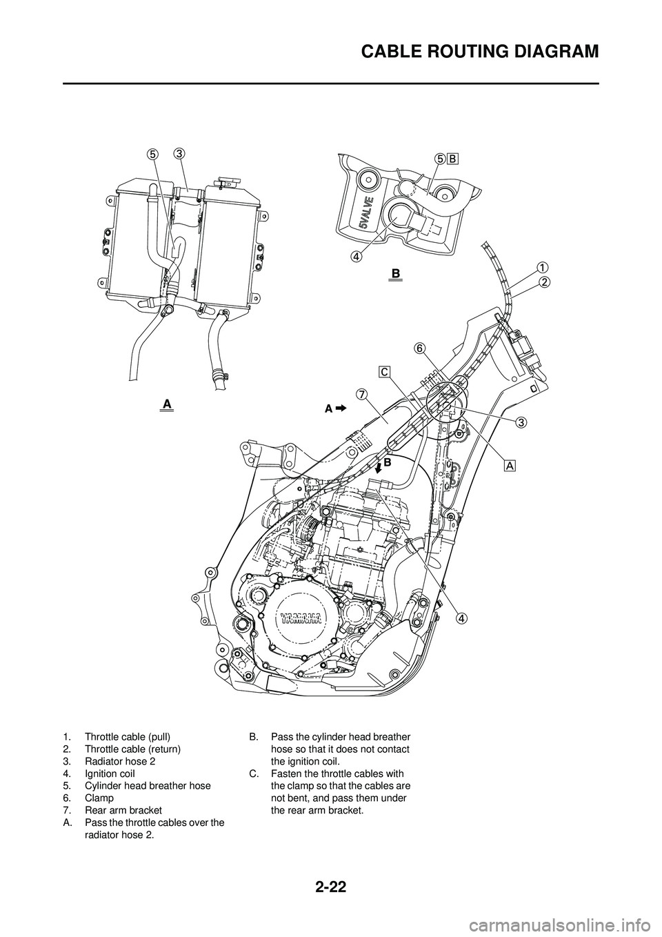
CABLE ROUTING DIAGRAM
1. Throttle cable (pull)
2. Throttle cable (return)
3. Radiator hose 2
4. Ignition coil
5. Cylinder head breather hose
6. Clamp
7. Rear arm bracket
A. Pass the throttle cables over the radiator hose 2. B. Pass the cylinder head breather
hose so that it does not contact
the ignition coil.
C. Fasten the throttle cables with the clamp so that the cables are
not bent, and pass them under
the rear arm bracket.
Page 51 of 192
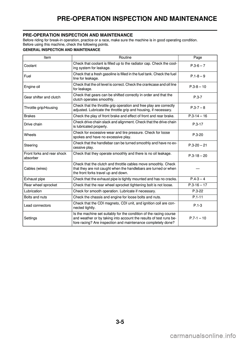
3-5
PRE-OPERATION INSPECTION AND MAINTENANCE
PRE-OPERATION INSPECTION AND MAINTENANCE
Before riding for break-in operation, practice or a race, make sure the machine is in good operating condition.
Before using this machine, check the following points.
GENERAL INSPECTION AND MAINTENANCEItem RoutinePage
Coolant Check that coolant is filled up to the radiator cap. Check the cool-
ing system for leakage. P.3-6 – 7
Fuel Check that a fresh gasoline is filled in the fuel tank. Check the fuel
line for leakage. P.1-8 – 9
Engine oil Check that the oil level is correct. Check the crankcase and oil line
for leakage. P.3-8 – 10
Gear shifter and clutch Check that gears can be shifted correctly in order and that the
clutch operates smoothly. P.3-7
Throttle grip/Housing Check that the throttle grip operation and free play are correctly
adjusted. Lubricate the throttle grip and housing, if necessary. P.3-7 – 8
Brakes Check the play of front brake and effect of front and rear brake. P.3-14 – 16
Drive chain Check drive chain slack and alignment. Check that the drive chain
is lubricated properly. P.3-17
Wheels Check for excessive wear and tire pressure. Check for loose
spokes and have no excessive play. P.3-20
Steering Check that the handlebar can be turned smoothly and have no ex-
cessive play. P.3-20 – 21
Front forks and rear shock
absorber Check that they operate smoothly and there is no oil leakage.
P.3-18 – 20
Cables (wires) Check that the clutch and throttle cables move smoothly. Check
that they are not caught when the handlebars are turned or when
the front forks travel up and down.
—
Exhaust pipe Check that the exhaust pipe is tightly mounted and has no cracks. P.4-3 – 4
Rear wheel sprocket Check that the rear wheel sprocket tightening bolt is not loose. P.3-16 – 17
Lubrication Check for smooth operation. Lubricate if necessary. P.3-22
Bolts and nuts Check the chassis and engine for loose bolts and nuts. P.1-11
Lead connectors Check that the CDI magneto, CDI unit, and ignition coil are con-
nected tightly. P.1-3
Settings Is the machine set suitably for the condition of the racing course
and weather or by taking into account the results of test runs be-
fore racing? Are inspection and maintenance completely done?
P.7-1 – 10
Page 56 of 192

3-10
ENGINE
• Oil hose clamp
9. Install: • Copper washer
• Oil filter element drain bolt
• Crankcase oil drain bolt
• Oil tank drain bolt
• Lower engine guard
10. Fill: • Engine oil
11. Check: • Oil leakage
12. Install: • Oil filler cap
• Washer (oil tank) • Bolt (oil tank)
13. Check: • Engine oil level
CHECKING THE OIL PRESSURE
1. Check: • Oil pressure
Checking steps:
a. Slightly loosen the oil pressure check bolt "1".
b. Start the engine and keep it idling until oil starts to seep from the oil
pressure check bolt. If no oil
comes out after one minute, turn
the engine off so it will not seize.
c. Check oil passages and oil pump for damage or leakage.
d. Start the engine after solving the
problem(s) and recheck the oil
pressure.
e. Tighten the oil pressure check
bolt.
ADJUSTING THE PILOT SCREW
1. Adjust:• Pilot screw "1"
Adjustment steps:
To optimize the fuel flow at a smaller
throttle opening, each machine's pilot
screw has been individually set at the
factory. Before adjusting the pilot
screw, turn it in fully and count the
number of turns. Record this number
as the factory-set number of turns
out.
a. Turn in the pilot screw until it is lightly seated.
b. Turn out the pilot screw by the factory-set number of turns.
ADJUSTING THE ENGINE IDLING
SPEED
1. Start the engine and thoroughly warm it up.
2. Adjust: • Engine idling speed
Adjustment steps:
a. Adjust the pilot screw. Refer to "ADJUSTING THE PI-
LOT SCREW" section.
b. Turn the throttle stop screw "1"
until the specified engine idling
speed.
Using a digital engine tachometer for
idle speed adjustment, detect the en-
gine idling speed by bringing the
sensing element "c" of the engine ta-
chometer close to the ignition coil "2".
Oil hose clamp:2 Nm (0.2 m•kg, 1.4
ft•lb)
Oil filter element drain
bolt: 10 Nm (1.0 m•kg, 7.2
ft•lb)
Crankcase oil drain bolt: 20 Nm (2.0 m•kg, 14
ft•lb)
Oil tank drain bolt: 18 Nm (1.8 m•kg, 13
ft•lb)
Lower engine guard: 10 Nm (1.0 m•kg, 7.2
ft•lb)
Oil quantity: Periodic oil change:1.05 L (0.92 Imp qt,
1.11 US qt)
With oil filter replace-
ment: 1.15 L (1.01 Imp qt,
1.22 US qt)
Total amount:
1.30 L (1.14 Imp qt,
1.37 US qt)Bolt (oil tank): 7 Nm (0.7 m•kg, 5.1
ft•lb)
Oil pressure check bolt: 10 Nm (1.0 m•kg, 7.2
ft•lb)
Pilot screw (example): 2-3/8 turns out
To increase idle speed→Turn the
throttle stop screw "1" in "a".
To decrease idle speed
→Turn
the throttle stop screw "1" out
"b".
Engine idling speed:1,900–2,100 r/min