YAMAHA YZ250F 2009 Owners Manual
Manufacturer: YAMAHA, Model Year: 2009, Model line: YZ250F, Model: YAMAHA YZ250F 2009Pages: 190, PDF Size: 12.83 MB
Page 131 of 190
4-61
TRANSMISSION, SHIFT CAM AND SHIFT FORK
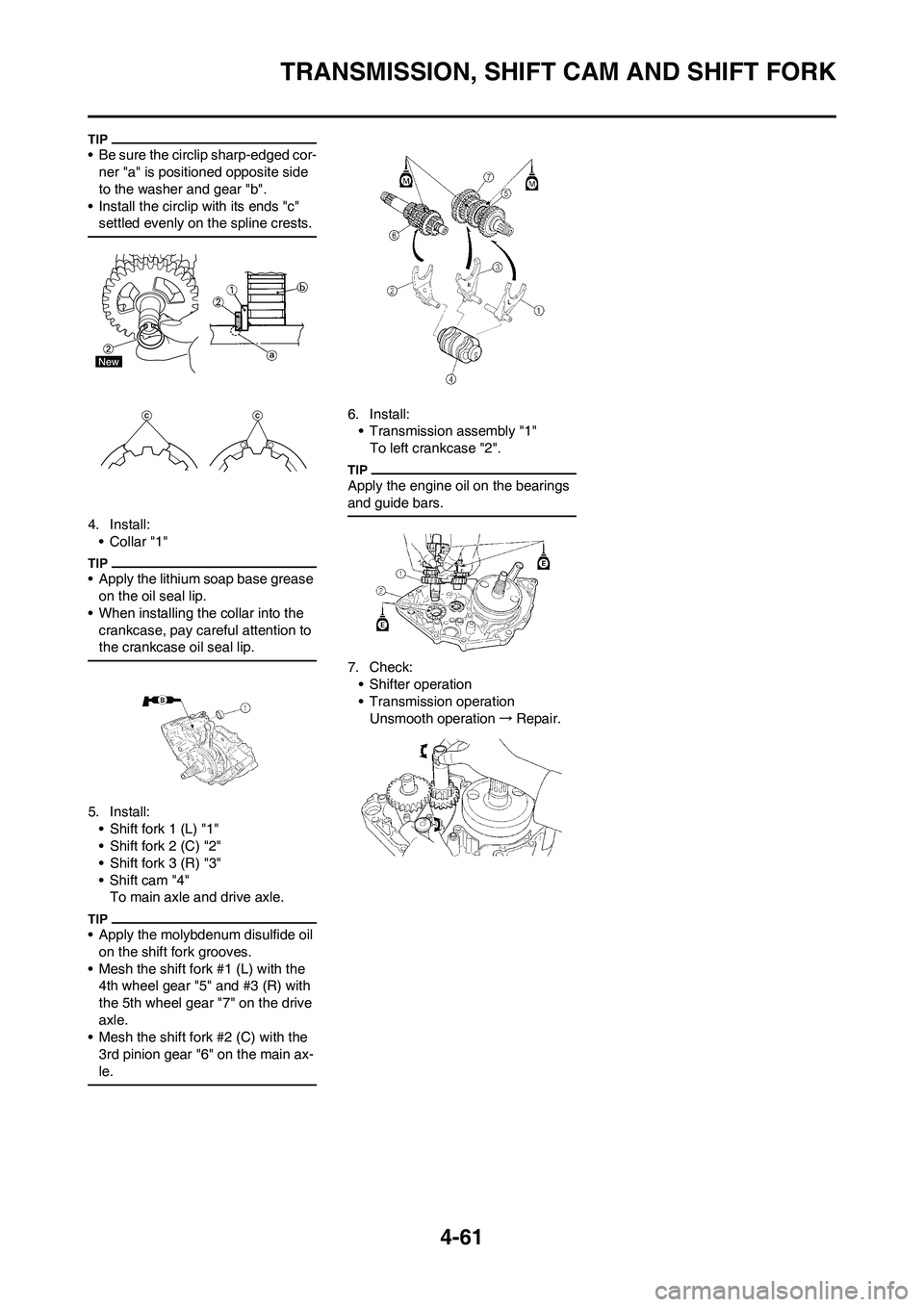
• Be sure the circlip sharp-edged cor-
ner "a" is positioned opposite side
to the washer and gear "b".
• Install the circlip with its ends "c"
settled evenly on the spline crests.
4. Install:
•Collar "1"
• Apply the lithium soap base grease
on the oil seal lip.
• When installing the collar into the
crankcase, pay careful attention to
the crankcase oil seal lip.
5. Install:
• Shift fork 1 (L) "1"
• Shift fork 2 (C) "2"
• Shift fork 3 (R) "3"
•Shift cam "4"
To main axle and drive axle.
• Apply the molybdenum disulfide oil
on the shift fork grooves.
• Mesh the shift fork #1 (L) with the
4th wheel gear "5" and #3 (R) with
the 5th wheel gear "7" on the drive
axle.
• Mesh the shift fork #2 (C) with the
3rd pinion gear "6" on the main ax-
le.
6. Install:
• Transmission assembly "1"
To left crankcase "2".
Apply the engine oil on the bearings
and guide bars.
7. Check:
• Shifter operation
• Transmission operation
Unsmooth operation→Repair.
Page 132 of 190
5-1
FRONT WHEEL AND REAR WHEEL
CHASSIS
This section is intended for those who have basic knowledge and skill concerning the servicing of Yamaha motorcycles
(e.g., Yamaha dealers, service engineers, etc.) Those who have little knowledge and skill concerning servicing are request-
ed not to undertake inspection, adjustment, disassembly, or reassembly only by reference to this manual. It may lead to
servicing trouble and mechanical damage.
FRONT WHEEL AND REAR WHEEL
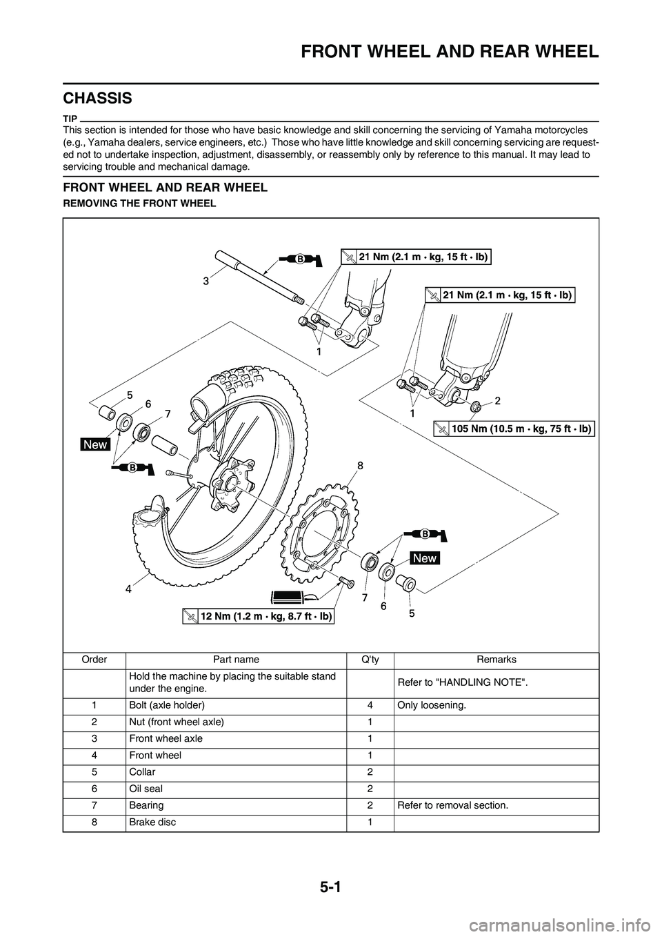
REMOVING THE FRONT WHEEL
Order Part name Q'ty Remarks
Hold the machine by placing the suitable stand
under the engine.Refer to "HANDLING NOTE".
1 Bolt (axle holder) 4 Only loosening.
2 Nut (front wheel axle) 1
3 Front wheel axle 1
4 Front wheel 1
5Collar 2
6 Oil seal 2
7 Bearing 2 Refer to removal section.
8Brake disc 1
Page 133 of 190
5-2
FRONT WHEEL AND REAR WHEEL
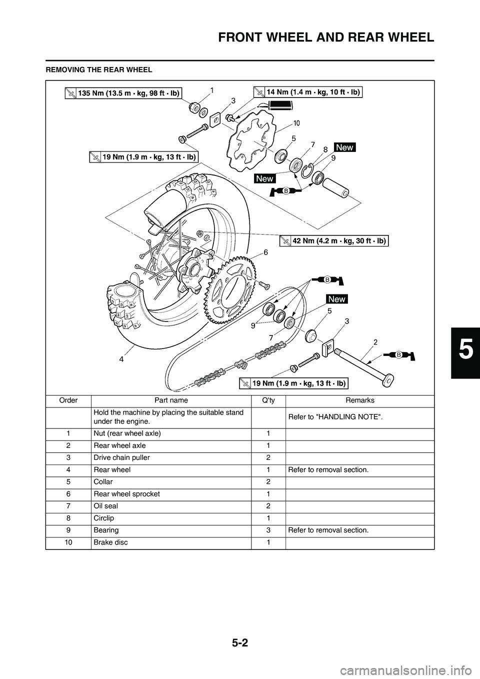
REMOVING THE REAR WHEEL
Order Part name Q'ty Remarks
Hold the machine by placing the suitable stand
under the engine.Refer to "HANDLING NOTE".
1 Nut (rear wheel axle) 1
2 Rear wheel axle 1
3 Drive chain puller 2
4 Rear wheel 1 Refer to removal section.
5Collar 2
6 Rear wheel sprocket 1
7 Oil seal 2
8 Circlip 1
9 Bearing 3 Refer to removal section.
10 Brake disc 1
5
Page 134 of 190
5-3
FRONT WHEEL AND REAR WHEEL
HANDLING NOTE
Support the machine securely so
there is no danger of it falling over.
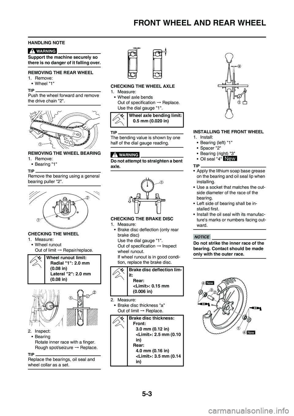
REMOVING THE REAR WHEEL
1. Remove:
• Wheel "1"
Push the wheel forward and remove
the drive chain "2".
REMOVING THE WHEEL BEARING
1. Remove:
• Bearing "1"
Remove the bearing using a general
bearing puller "2".
CHECKING THE WHEEL
1. Measure:
• Wheel runout
Out of limit → Repair/replace.
2. Inspect:
• Bearing
Rotate inner race with a finger.
Rough spot/seizure → Replace.
Replace the bearings, oil seal and
wheel collar as a set.
CHECKING THE WHEEL AXLE
1. Measure:
• Wheel axle bends
Out of specification → Replace.
Use the dial gauge "1".
The bending value is shown by one
half of the dial gauge reading.
Do not attempt to straighten a bent
axle.
CHECKING THE BRAKE DISC
1. Measure:
• Brake disc deflection (only rear
brake disc)
Use the dial gauge "1".
Out of specification → Inspect
wheel runout.
If wheel runout is in good condi-
tion, replace the brake disc.
2. Measure:
• Brake disc thickness "a"
Out of limit → Replace.INSTALLING THE FRONT WHEEL
1. Install:
• Bearing (left) "1"
•Spacer "2"
• Bearing (right) "3"
•Oil seal "4"
• Apply the lithium soap base grease
on the bearing and oil seal lip when
installing.
• Use a socket that matches the out-
side diameter of the race of the
bearing.
• Left side of bearing shall be in-
stalled first.
• Install the oil seal with its manufac-
ture's marks or numbers facing out-
ward.
Do not strike the inner race of the
bearing. Contact should be made
only with the outer race.
Wheel runout limit:
Radial "1": 2.0 mm
(0.08 in)
Lateral "2": 2.0 mm
(0.08 in)
Wheel axle bending limit:
0.5 mm (0.020 in)
Brake disc deflection lim-
it:
Rear:
(0.006 in)
Brake disc thickness:
Front:
3.0 mm (0.12 in)
in)
Rear:
4.0 mm (0.16 in)
in)
Page 135 of 190

5-4
FRONT WHEEL AND REAR WHEEL
2. Install:
•Brake disc "1"
• Bolt (brake disc) "2"
Tighten the bolts in stage, using a
crisscross pattern.
3. Install:
•Collar "1"
• Apply the lithium soap base grease
on the oil seal lip.
• Install the collars with their projec-
tions "a" facing the wheel.
4. Install:
• Wheel
Install the brake disc "1" between the
brake pads "2" correctly.
5. Install:
• Wheel axle "1"
Apply the lithium soap base grease
on the wheel axle.
6. Install:
• Nut (wheel axle) "1"
7. Tighten:
• Bolt (axle holder) "1"
Before tightening the bolt, fit the
wheel axle to the axle holder by strok-
ing the front fork several times with
the front brake applied.
INSTALLING THE REAR WHEEL
1. Install:
• Bearing (right) "1"
•Circlip "2"
•Spacer "3"
• Bearing (left) "4"
• Oil seal "5"
• Apply the lithium soap base grease
on the bearing and oil seal lip when
installing.
• Install the bearing with seal facing
outward.
• Use a socket that matches the out-
side diameter of the race of the
bearing.
• Right side of bearing shall be in-
stalled first.
• Install the oil seal with its manufac-
ture's marks or numbers facing out-
ward.
Do not strike the inner race of the
bearing. Contact should be made
only with the outer race.
2. Install:
• Brake disc "1"
• Bolt (brake disc) "2"
Tighten the bolts in stage, using a
crisscross pattern.
3. Install:
• Rear wheel sprocket "1"
• Bolt (rear wheel sprocket) "2"
• Washer (rear wheel sprocket) "3"
• Nut (rear wheel sprocket) "4"
Tighten the nuts in stage, using a
crisscross pattern.
Bolt (brake disc):
12 Nm (1.2 m•kg, 8.7
ft•lb)
Nut (wheel axle):
105 Nm (10.5 m•kg, 75
ft•lb)
Bolt (axle holder):
21 Nm (2.1 m•kg, 15
ft•lb)
Bolt (brake disc):
14 Nm (1.4 m•kg, 10
ft•lb)
Nut (rear wheel sprock-
et):
42 Nm (4.2 m•kg, 30
ft•lb)
Page 136 of 190
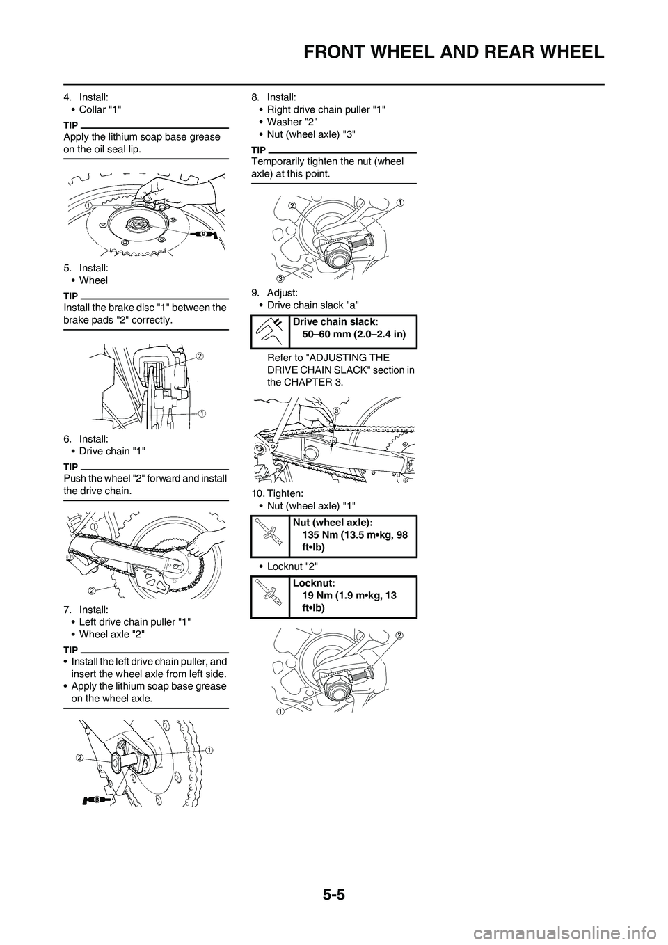
5-5
FRONT WHEEL AND REAR WHEEL
4. Install:
•Collar "1"
Apply the lithium soap base grease
on the oil seal lip.
5. Install:
• Wheel
Install the brake disc "1" between the
brake pads "2" correctly.
6. Install:
• Drive chain "1"
Push the wheel "2" forward and install
the drive chain.
7. Install:
• Left drive chain puller "1"
• Wheel axle "2"
• Install the left drive chain puller, and
insert the wheel axle from left side.
• Apply the lithium soap base grease
on the wheel axle.
8. Install:
• Right drive chain puller "1"
•Washer "2"
• Nut (wheel axle) "3"
Temporarily tighten the nut (wheel
axle) at this point.
9. Adjust:
• Drive chain slack "a"
Refer to "ADJUSTING THE
DRIVE CHAIN SLACK" section in
the CHAPTER 3.
10. Tighten:
• Nut (wheel axle) "1"
• Locknut "2"
Drive chain slack:
50–60 mm (2.0–2.4 in)
Nut (wheel axle):
135 Nm (13.5 m•kg, 98
ft•lb)
Locknut:
19 Nm (1.9 m•kg, 13
ft•lb)
Page 137 of 190
5-6
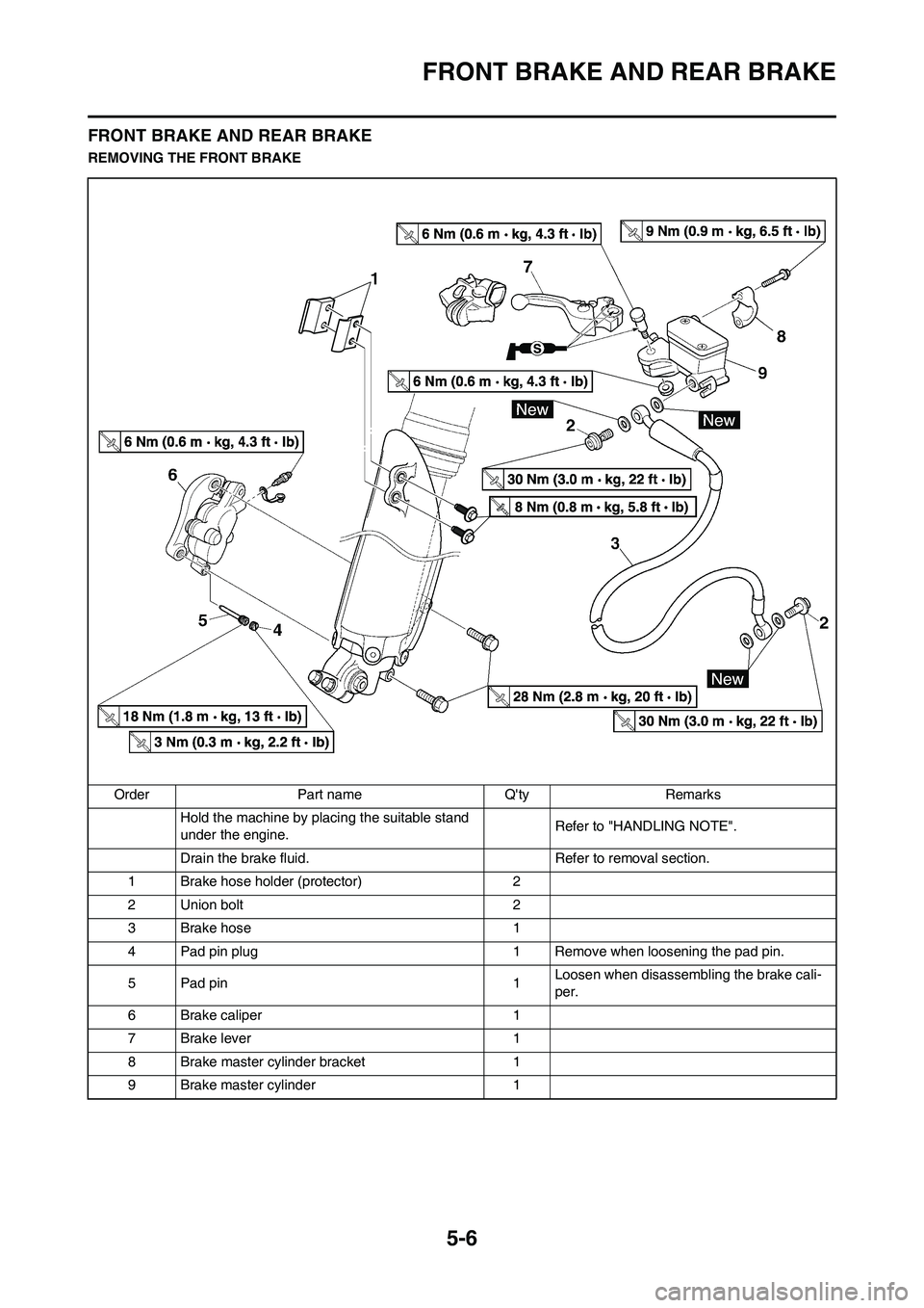
FRONT BRAKE AND REAR BRAKE
FRONT BRAKE AND REAR BRAKE
REMOVING THE FRONT BRAKE
Order Part name Q'ty Remarks
Hold the machine by placing the suitable stand
under the engine.Refer to "HANDLING NOTE".
Drain the brake fluid. Refer to removal section.
1 Brake hose holder (protector) 2
2 Union bolt 2
3Brake hose 1
4 Pad pin plug 1 Remove when loosening the pad pin.
5 Pad pin 1Loosen when disassembling the brake cali-
per.
6 Brake caliper 1
7Brake lever 1
8 Brake master cylinder bracket 1
9 Brake master cylinder 1
Page 138 of 190
5-7
FRONT BRAKE AND REAR BRAKE
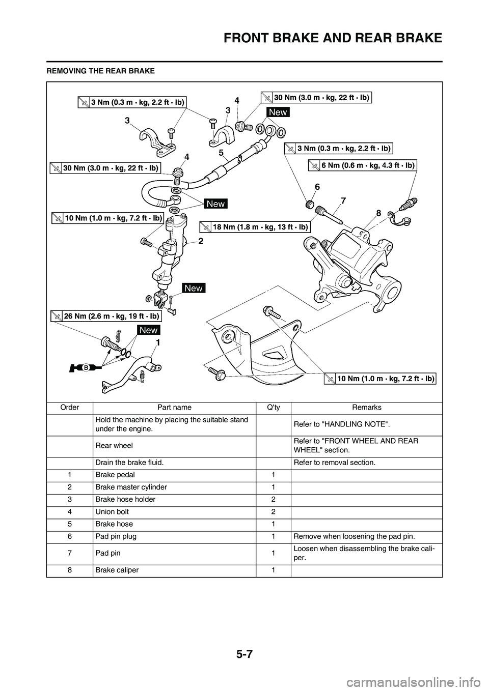
REMOVING THE REAR BRAKE
Order Part name Q'ty Remarks
Hold the machine by placing the suitable stand
under the engine.Refer to "HANDLING NOTE".
Rear wheel Refer to "FRONT WHEEL AND REAR
WHEEL" section.
Drain the brake fluid. Refer to removal section.
1 Brake pedal 1
2 Brake master cylinder 1
3 Brake hose holder 2
4 Union bolt 2
5Brake hose 1
6 Pad pin plug 1 Remove when loosening the pad pin.
7 Pad pin 1Loosen when disassembling the brake cali-
per.
8 Brake caliper 1
Page 139 of 190
5-8
FRONT BRAKE AND REAR BRAKE
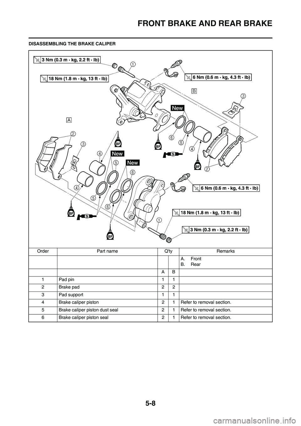
DISASSEMBLING THE BRAKE CALIPER
Order Part name Q'ty Remarks
A. Front
B. Rear
AB
1 Pad pin 1 1
2Brake pad 22
3 Pad support 1 1
4 Brake caliper piston 2 1 Refer to removal section.
5 Brake caliper piston dust seal 2 1 Refer to removal section.
6 Brake caliper piston seal 2 1 Refer to removal section.
Page 140 of 190
5-9
FRONT BRAKE AND REAR BRAKE
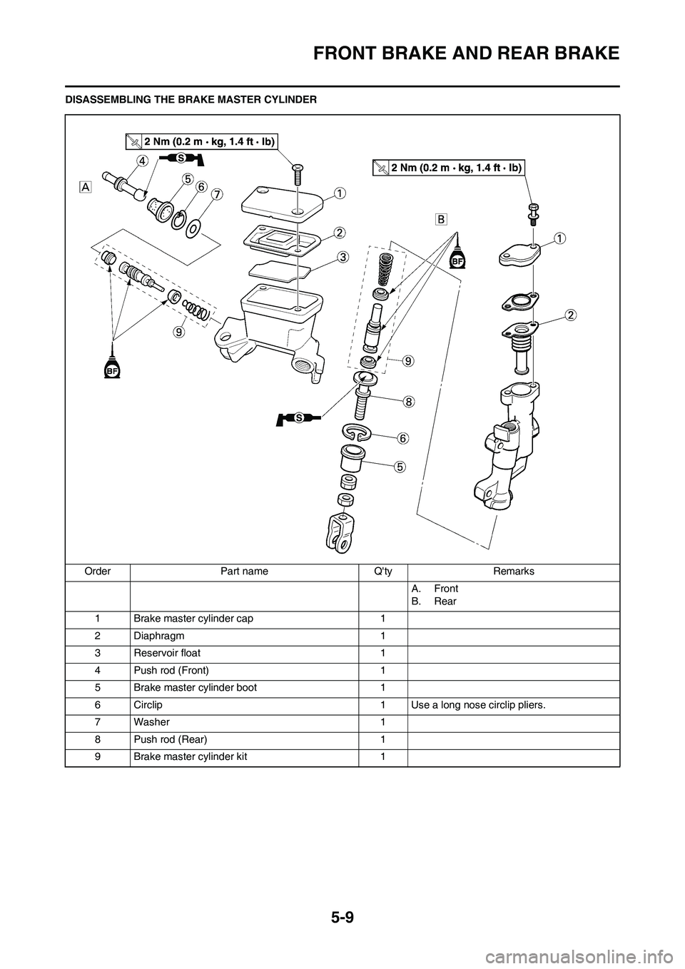
DISASSEMBLING THE BRAKE MASTER CYLINDER
Order Part name Q'ty Remarks
A. Front
B. Rear
1 Brake master cylinder cap 1
2 Diaphragm 1
3 Reservoir float 1
4 Push rod (Front) 1
5 Brake master cylinder boot 1
6 Circlip 1 Use a long nose circlip pliers.
7 Washer 1
8 Push rod (Rear) 1
9 Brake master cylinder kit 1