YAMAHA YZ250F 2009 Service Manual
Manufacturer: YAMAHA, Model Year: 2009, Model line: YZ250F, Model: YAMAHA YZ250F 2009Pages: 190, PDF Size: 12.83 MB
Page 41 of 190
2-19
CABLE ROUTING DIAGRAM
F. Pass the clutch cable in front of
the radiator mounting boss.
G. Pass the fuel hose on the out-
side of throttle position sensor
lead.
H. Pass the carburetor breater hos-
es so that they are not pinched
between the upper engine
bracket and carburetor.
I. Pass the carburetor breather
hoses and overflow hose so that
all there hoses do not contact
the rear shock absorber.
Page 42 of 190
2-20
CABLE ROUTING DIAGRAM
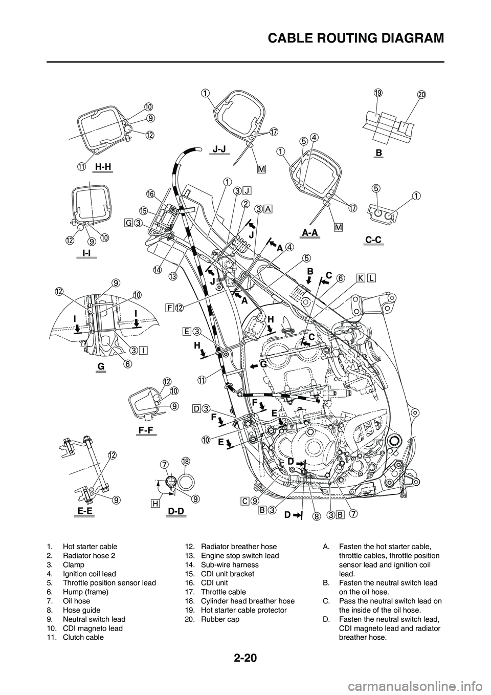
1. Hot starter cable
2. Radiator hose 2
3. Clamp
4. Ignition coil lead
5. Throttle position sensor lead
6. Hump (frame)
7. Oil hose
8. Hose guide
9. Neutral switch lead
10. CDI magneto lead
11. Clutch cable12. Radiator breather hose
13. Engine stop switch lead
14. Sub-wire harness
15. CDI unit bracket
16. CDI unit
17. Throttle cable
18. Cylinder head breather hose
19. Hot starter cable protector
20. Rubber capA. Fasten the hot starter cable,
throttle cables, throttle position
sensor lead and ignition coil
lead.
B. Fasten the neutral switch lead
on the oil hose.
C. Pass the neutral switch lead on
the inside of the oil hose.
D. Fasten the neutral switch lead,
CDI magneto lead and radiator
breather hose.
Page 43 of 190
2-21
CABLE ROUTING DIAGRAM
E. Fasten the neutral switch lead,
CDI magneto lead, radiator
breather hose and clutch cable
over the radiator mounting boss.
F. Pass the radiator breather hose
in front of the radiator, on the left
of the chassis, and then be-
tween the frame and radiator
hose 4.
G. Fasten the sub-wire harness
and engine stop switch lead to
the CDI unit bracket at the white-
taped portion of the subwire har-
ness and with the clamp ends
facing downward.
H. Locate the clamp ends in the ar-
rowed range.
I. Fasten the neutral switch lead
and CDI magneto lead over the
hump of the frame.
J. Fasten the hot starter cable and
throttle cable onto the frame.
K. Fasten the throttle position sen-
sor lead and the hot starter ca-
ble.
L. Locate the clamp between the
hot starter cable protector and
rubber cap.
M. Locate the clamp ends under
the throttle cable, and after
clamping, leave the other end as
is and do not cut it. [clamp:L=
270mm (10.6 in)]
Page 44 of 190
2-22
CABLE ROUTING DIAGRAM
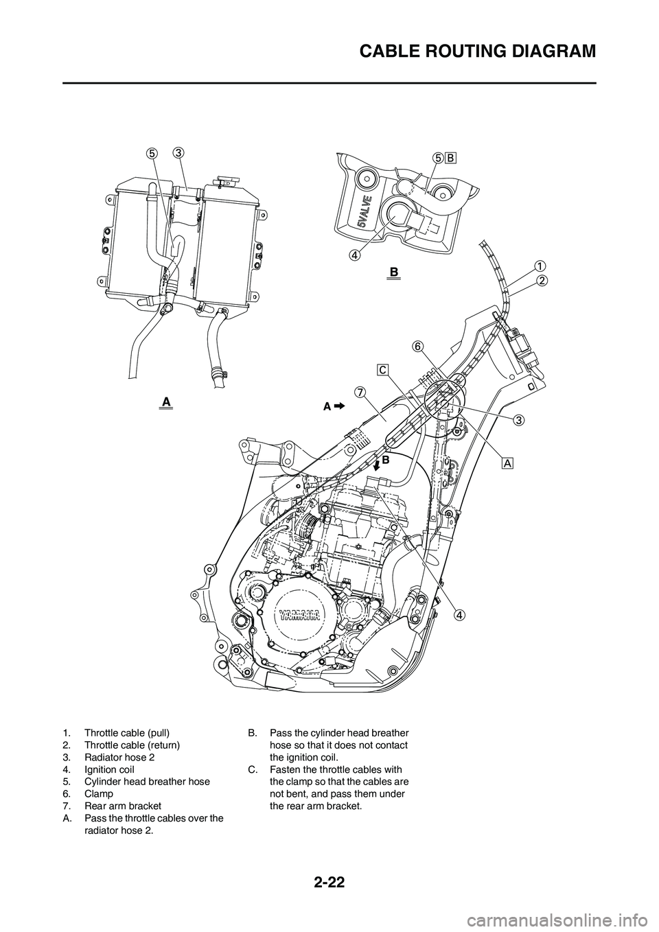
1. Throttle cable (pull)
2. Throttle cable (return)
3. Radiator hose 2
4. Ignition coil
5. Cylinder head breather hose
6. Clamp
7. Rear arm bracket
A. Pass the throttle cables over the
radiator hose 2. B. Pass the cylinder head breather
hose so that it does not contact
the ignition coil.
C. Fasten the throttle cables with
the clamp so that the cables are
not bent, and pass them under
the rear arm bracket.
Page 45 of 190
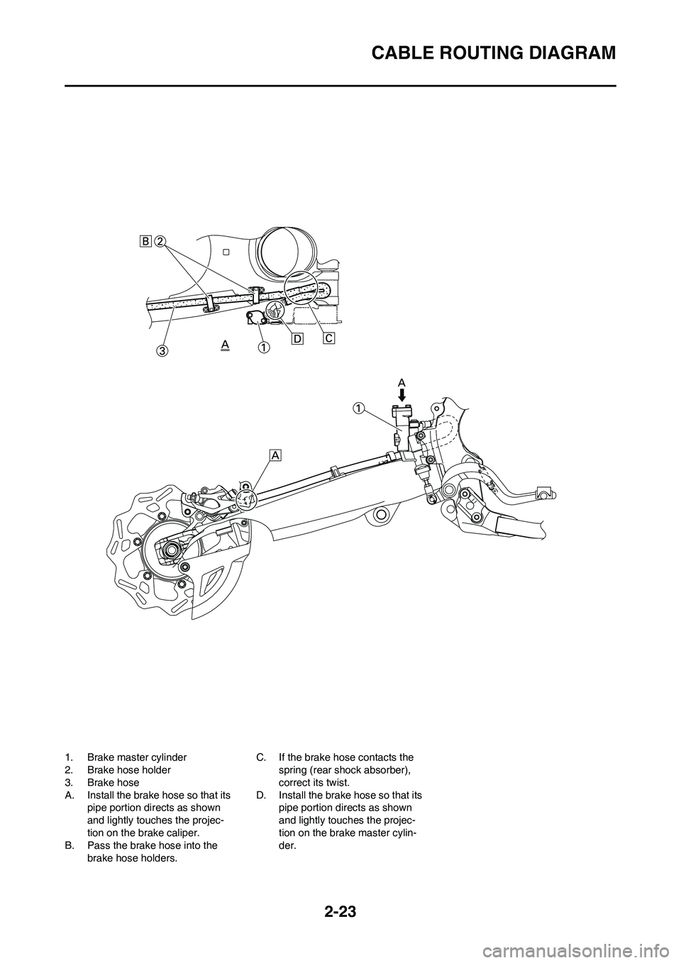
2-23
CABLE ROUTING DIAGRAM
1. Brake master cylinder
2. Brake hose holder
3. Brake hose
A. Install the brake hose so that its
pipe portion directs as shown
and lightly touches the projec-
tion on the brake caliper.
B. Pass the brake hose into the
brake hose holders.C. If the brake hose contacts the
spring (rear shock absorber),
correct its twist.
D. Install the brake hose so that its
pipe portion directs as shown
and lightly touches the projec-
tion on the brake master cylin-
der.
Page 46 of 190
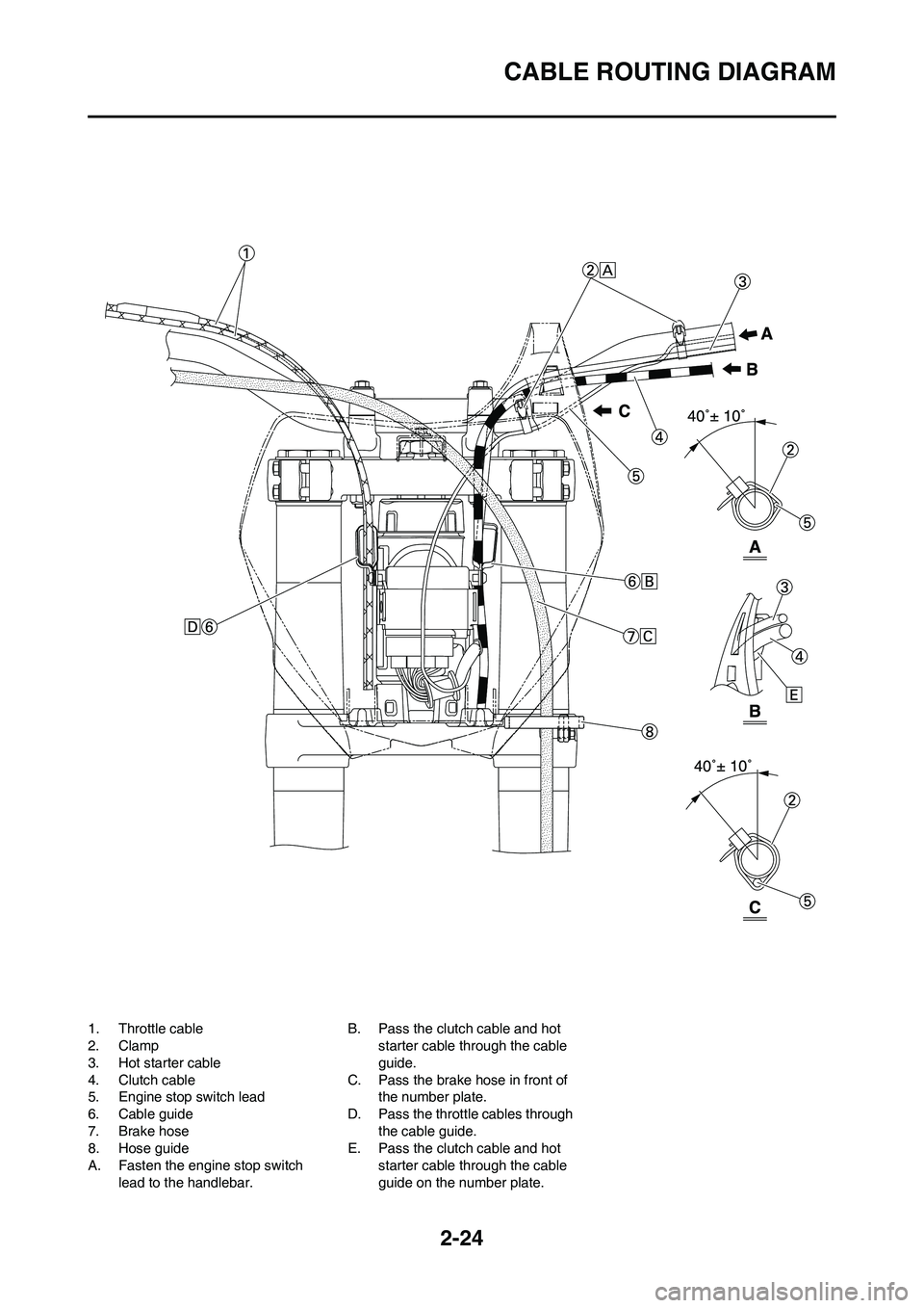
2-24
CABLE ROUTING DIAGRAM
1. Throttle cable
2. Clamp
3. Hot starter cable
4. Clutch cable
5. Engine stop switch lead
6. Cable guide
7. Brake hose
8. Hose guide
A. Fasten the engine stop switch
lead to the handlebar.B. Pass the clutch cable and hot
starter cable through the cable
guide.
C. Pass the brake hose in front of
the number plate.
D. Pass the throttle cables through
the cable guide.
E. Pass the clutch cable and hot
starter cable through the cable
guide on the number plate.
Page 47 of 190
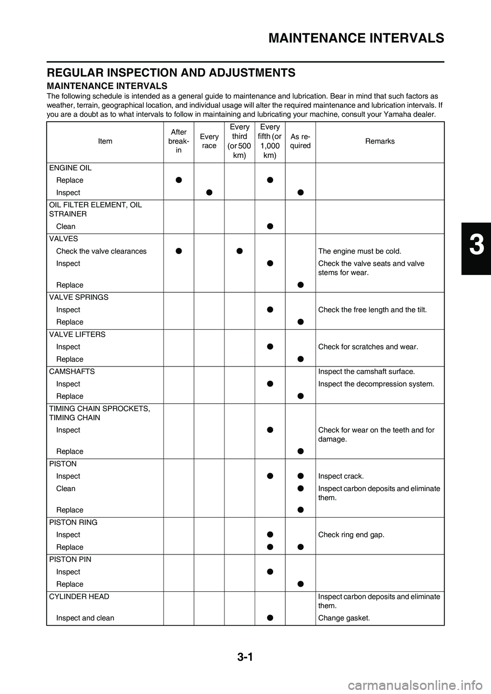
3-1
MAINTENANCE INTERVALS
REGULAR INSPECTION AND ADJUSTMENTS
MAINTENANCE INTERVALS
The following schedule is intended as a general guide to maintenance and lubrication. Bear in mind that such factors as
weather, terrain, geographical location, and individual usage will alter the required maintenance and lubrication intervals. If
you are a doubt as to what intervals to follow in maintaining and lubricating your machine, consult your Yamaha dealer.
ItemAfter
break-
inEvery
race
Every
third
(or 500
km)Every
fifth (or
1,000
km)
As re-
quiredRemarks
ENGINE OIL
Replace●●
Inspect●●
OIL FILTER ELEMENT, OIL
STRAINER
Clean●
VALVES
Check the valve clearances●●The engine must be cold.
Inspect●Check the valve seats and valve
stems for wear.
Replace●
VALVE SPRINGS
Inspect●Check the free length and the tilt.
Replace●
VALVE LIFTERS
Inspect●Check for scratches and wear.
Replace●
CAMSHAFTS Inspect the camshaft surface.
Inspect●Inspect the decompression system.
Replace●
TIMING CHAIN SPROCKETS,
TIMING CHAIN
Inspect●Check for wear on the teeth and for
damage.
Replace●
PISTON
Inspect●●Inspect crack.
Clean●Inspect carbon deposits and eliminate
them.
Replace●
PISTON RING
Inspect●Check ring end gap.
Replace●●
PISTON PIN
Inspect●
Replace●
CYLINDER HEAD Inspect carbon deposits and eliminate
them.
Inspect and clean●Change gasket.
3
Page 48 of 190
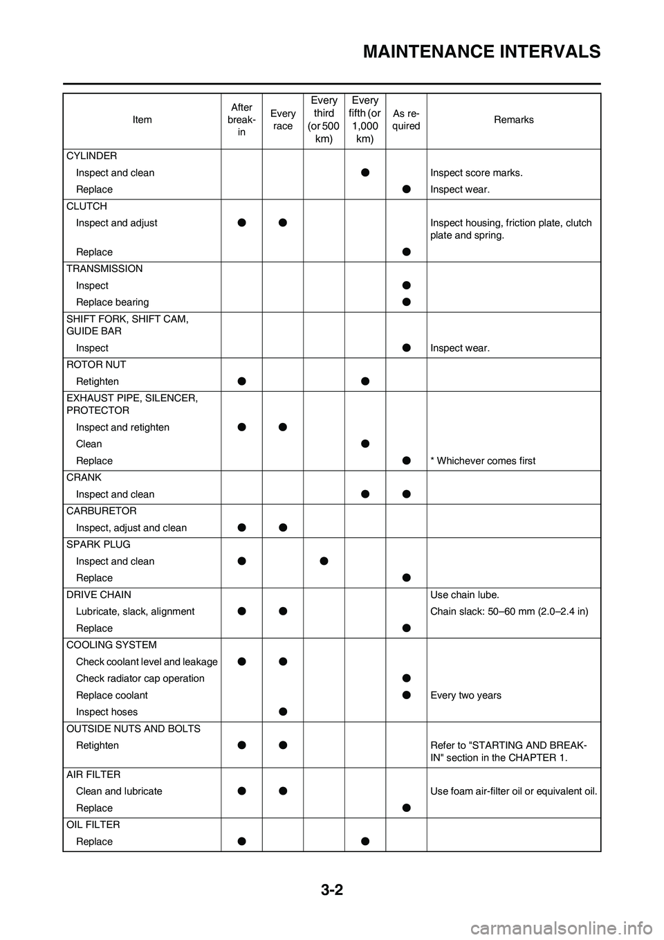
3-2
MAINTENANCE INTERVALS
CYLINDER
Inspect and clean●Inspect score marks.
Replace●Inspect wear.
CLUTCH
Inspect and adjust●●Inspect housing, friction plate, clutch
plate and spring.
Replace●
TRANSMISSION
Inspect●
Replace bearing●
SHIFT FORK, SHIFT CAM,
GUIDE BAR
Inspect●Inspect wear.
ROTOR NUT
Retighten●●
EXHAUST PIPE, SILENCER,
PROTECTOR
Inspect and retighten●●
Clean●
Replace●* Whichever comes first
CRANK
Inspect and clean●●
CARBURETOR
Inspect, adjust and clean●●
SPARK PLUG
Inspect and clean●●
Replace●
DRIVE CHAIN Use chain lube.
Lubricate, slack, alignment●●Chain slack: 50–60 mm (2.0–2.4 in)
Replace●
COOLING SYSTEM
Check coolant level and leakage●●
Check radiator cap operation●
Replace coolant●Every two years
Inspect hoses●
OUTSIDE NUTS AND BOLTS
Retighten●●Refer to "STARTING AND BREAK-
IN" section in the CHAPTER 1.
AIR FILTER
Clean and lubricate●●Use foam air-filter oil or equivalent oil.
Replace●
OIL FILTER
Replace●● ItemAfter
break-
inEvery
race
Every
third
(or 500
km)Every
fifth (or
1,000
km)
As re-
quiredRemarks
Page 49 of 190
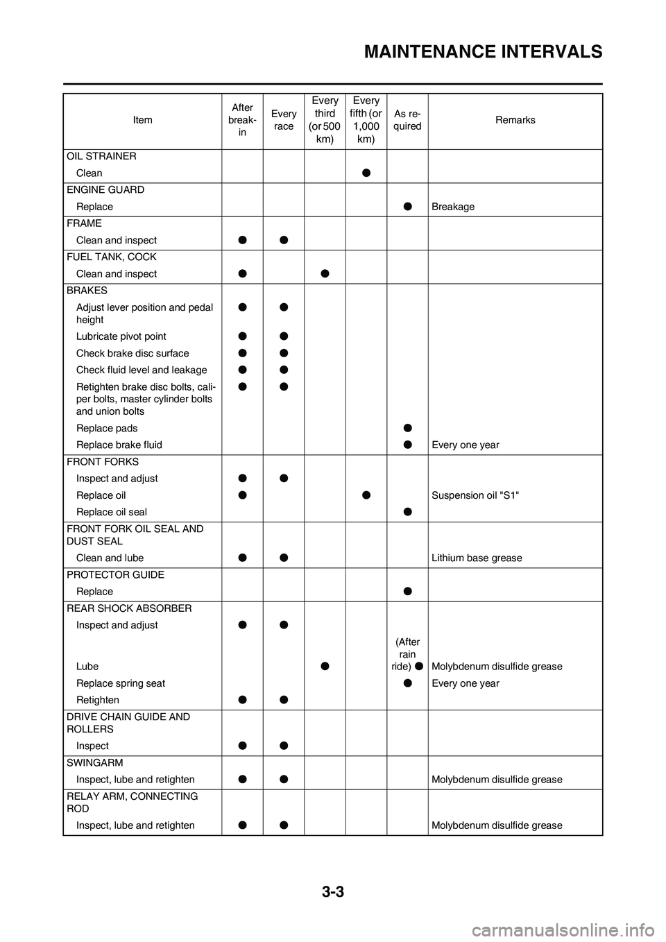
3-3
MAINTENANCE INTERVALS
OIL STRAINER
Clean●
ENGINE GUARD
Replace●Breakage
FRAME
Clean and inspect●●
FUEL TANK, COCK
Clean and inspect●●
BRAKES
Adjust lever position and pedal
height●●
Lubricate pivot point●●
Check brake disc surface●●
Check fluid level and leakage●●
Retighten brake disc bolts, cali-
per bolts, master cylinder bolts
and union bolts●●
Replace pads●
Replace brake fluid●Every one year
FRONT FORKS
Inspect and adjust●●
Replace oil●●Suspension oil "S1"
Replace oil seal●
FRONT FORK OIL SEAL AND
DUST SEAL
Clean and lube●●Lithium base grease
PROTECTOR GUIDE
Replace●
REAR SHOCK ABSORBER
Inspect and adjust●●
Lube●(After
rain
ride)●Molybdenum disulfide grease
Replace spring seat●Every one year
Retighten●●
DRIVE CHAIN GUIDE AND
ROLLERS
Inspect●●
SWINGARM
Inspect, lube and retighten●●Molybdenum disulfide grease
RELAY ARM, CONNECTING
ROD
Inspect, lube and retighten●●Molybdenum disulfide grease ItemAfter
break-
inEvery
race
Every
third
(or 500
km)Every
fifth (or
1,000
km)
As re-
quiredRemarks
Page 50 of 190
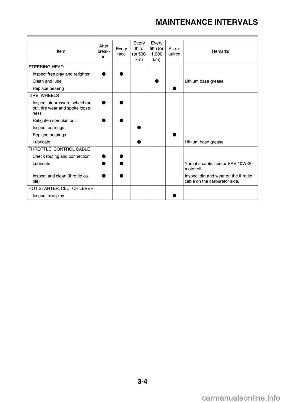
3-4
MAINTENANCE INTERVALS
STEERING HEAD
Inspect free play and retighten●●
Clean and lube●Lithium base grease
Replace bearing●
TIRE, WHEELS
Inspect air pressure, wheel run-
out, tire wear and spoke loose-
ness●●
Retighten sprocket bolt●●
Inspect bearings●
Replace bearings●
Lubricate●Lithium base grease
THROTTLE, CONTROL CABLE
Check routing and connection●●
Lubricate●●Yamaha cable lube or SAE 10W-30
motor oil
Inspect and clean (throttle ca-
ble)●●Inspect dirt and wear on the throttle
cable on the carburetor side.
HOT STARTER, CLUTCH LEVER
Inspect free play● ItemAfter
break-
inEvery
race
Every
third
(or 500
km)Every
fifth (or
1,000
km)
As re-
quiredRemarks