YAMAHA YZ250F 2010 Owners Manual
Manufacturer: YAMAHA, Model Year: 2010, Model line: YZ250F, Model: YAMAHA YZ250F 2010Pages: 196, PDF Size: 13.74 MB
Page 171 of 196
5-34
SWINGARM
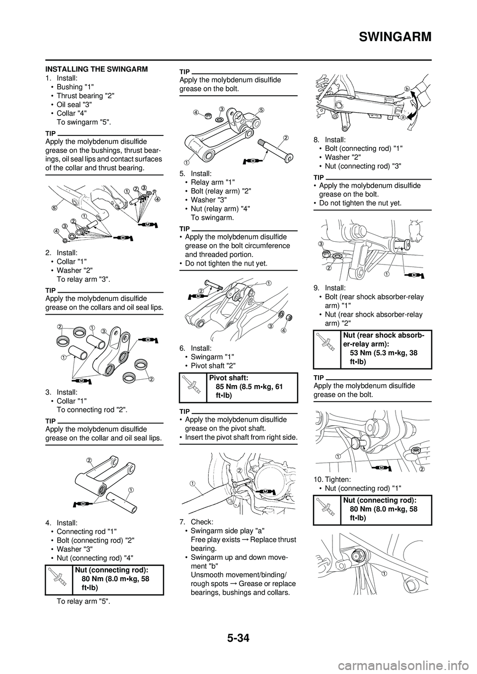
INSTALLING THE SWINGARM
1. Install:• Bushing "1"
• Thrust bearing "2"
• Oil seal "3"
•Collar "4"To swingarm "5".
Apply the molybdenum disulfide
grease on the bushings, thrust bear-
ings, oil seal lips and contact surfaces
of the collar and thrust bearing.
2. Install:•Collar "1"
• Washer "2"
To relay arm "3".
Apply the molybdenum disulfide
grease on the collars and oil seal lips.
3. Install:•Collar "1"To connecting rod "2".
Apply the molybdenum disulfide
grease on the collar and oil seal lips.
4. Install:• Connecting rod "1"
• Bolt (connecting rod) "2"
• Washer "3"
• Nut (connecting rod) "4"
To relay arm "5".
Apply the molybdenum disulfide
grease on the bolt.
5. Install:• Relay arm "1"
• Bolt (relay arm) "2"
• Washer "3"
• Nut (relay arm) "4"To swingarm.
• Apply the molybdenum disulfide
grease on the bolt circumference
and threaded portion.
• Do not tighten the nut yet.
6. Install: • Swingarm "1"
• Pivot shaft "2"
• Apply the molybdenum disulfide
grease on the pivot shaft.
• Insert the pivot shaft from right side.
7. Check:
• Swingarm side play "a"Free play exists →Replace thrust
bearing.
• Swingarm up and down move- ment "b"
Unsmooth movement/binding/
rough spots →Grease or replace
bearings, bushings and collars. 8. Install:
• Bolt (connecting rod) "1"
• Washer "2"
• Nut (connecting rod) "3"
• Apply the molybdenum disulfide grease on the bolt.
• Do not tighten the nut yet.
9. Install: • Bolt (rear shock absorber-relay arm) "1"
• Nut (rear shock absorber-relay
arm) "2"
Apply the molybdenum disulfide
grease on the bolt.
10. Tighten:• Nut (connecting rod) "1"
Nut (connecting rod): 80 Nm (8.0 m•kg, 58
ft•lb)
Pivot shaft:85 Nm (8.5 m•kg, 61
ft•lb)
Nut (rear shock absorb-
er-relay arm): 53 Nm (5.3 m•kg, 38
ft•lb)
Nut (connecting rod): 80 Nm (8.0 m•kg, 58
ft•lb)
Page 172 of 196
5-35
SWINGARM
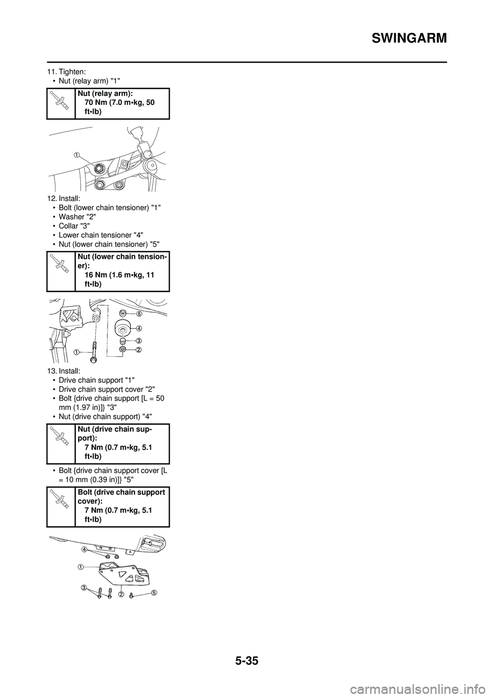
11. Tighten:• Nut (relay arm) "1"
12. Install: • Bolt (lower chain tensioner) "1"
• Washer "2"
•Collar "3"
• Lower chain tensioner "4"
• Nut (lower chain tensioner) "5"
13. Install: • Drive chain support "1"
• Drive chain support cover "2"
• Bolt {drive chain support [L = 50 mm (1.97 in)]} "3"
• Nut (drive chain support) "4"
• Bolt {drive chain support cover [L
= 10 mm (0.3 9 in)]} "5"
Nut (relay arm):
70 Nm (7.0 m•kg, 50
ft•lb)
Nut (lower chain tension-
er): 16 Nm (1.6 m•kg, 11
ft•lb)
Nut (drive chain sup-
port): 7 Nm (0.7 m•kg, 5.1
ft•lb)
Bolt (drive chain support
cover): 7 Nm (0.7 m•kg, 5.1
ft•lb)
Page 173 of 196
5-36
REAR SHOCK ABSORBER
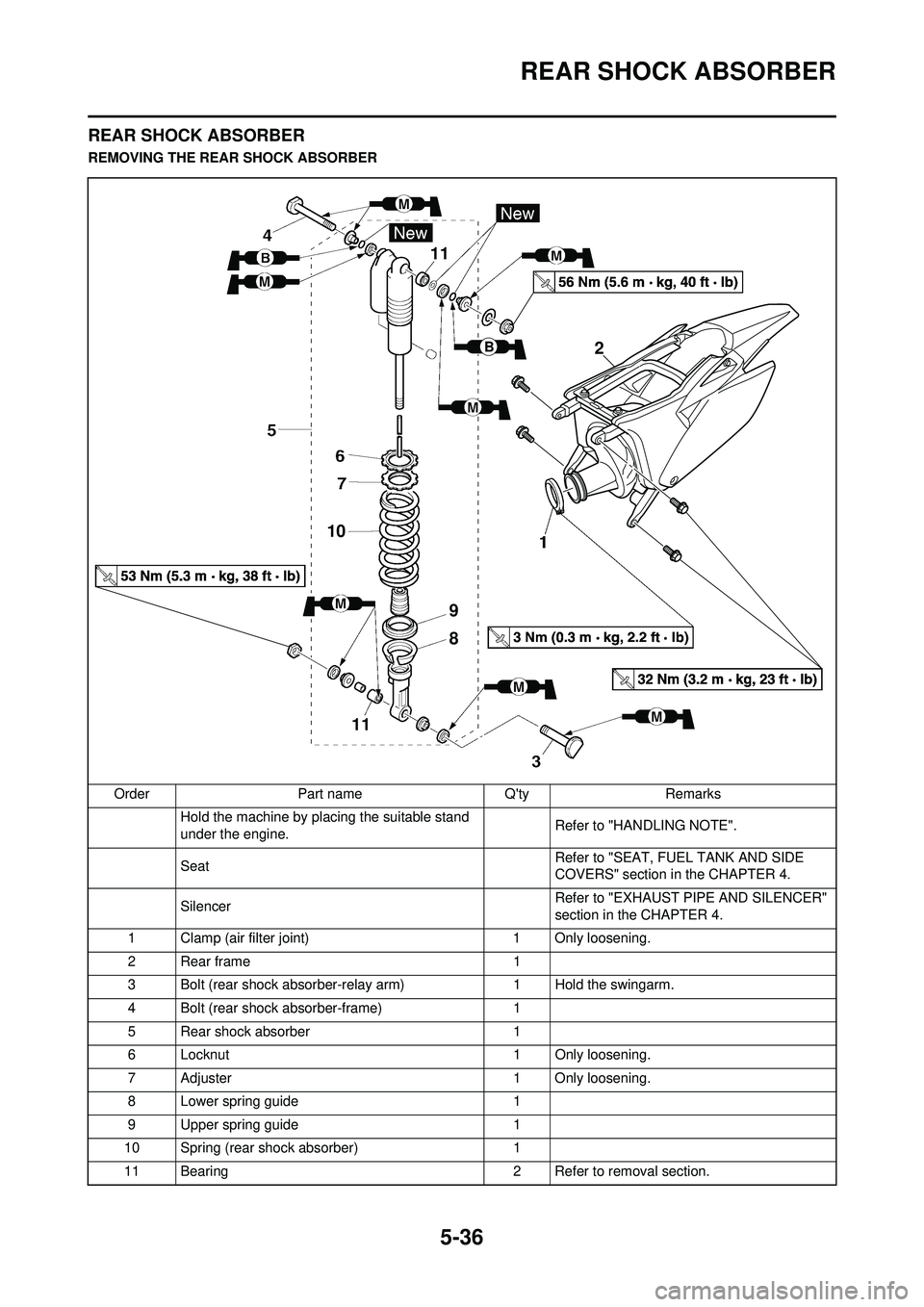
REAR SHOCK ABSORBER
REMOVING THE REAR SHOCK ABSORBEROrder Part name Q'ty Remarks Hold the machine by placing the suitable stand
under the engine. Refer to "HANDLING NOTE".
Seat Refer to "SEAT, FUEL TANK AND SIDE
COVERS" section in the CHAPTER 4.
Silencer Refer to "EXHAUST PIPE AND SILENCER"
section in the CHAPTER 4.
1 Clamp (air filter joint) 1 Only loosening.
2Rear frame 1
3 Bolt (rear shock absorber-relay arm) 1 Hold the swingarm.
4 Bolt (rear shock absorber-frame) 1
5 Rear shock absorber 1
6 Locknut 1 Only loosening.
7 Adjuster 1 Only loosening.
8 Lower spring guide 1
9 Upper spring guide 1
10 Spring (rear shock absorber) 1
11 Bearing 2 Refer to removal section.
B2
9
8
10
11
11
Page 174 of 196
5-37
REAR SHOCK ABSORBER
HANDLING NOTE
• Support the machine securely so there is no danger of it falling
over.
• This rear shock absorber is pro-
vided with a separate type tank
filled with high-pressure nitro-
gen gas. To prevent the danger
of explosion, read and under-
stand the follow ing information
before handling the shock ab-
sorber. The manufacturer can
not be held responsible for prop-
erty damage or personal injury
that may result from improper
handling.
• Never tamper or attempt to dis-
assemble the cylinder or the
tank.
• Never throw the rear shock ab-
sorber into an open flame or
other high heat. The rear shock
absorber may explode as a re-
sult of nitrogen gas expansion
and/ or damage to the hose.
• Be careful not to damage any
part of the gas tank. A damaged
gas tank will impair the damp-
ing performance or cause a
malfunction.
• Take care not to scratch the
contact surface of the piston
rod with the cylinder; or oil
could leak out.
• Never attempt to remove the plug at the bottom of the nitro-
gen gas tank. It is very danger-
ous to remove the plug.
• When scrapping the rear shock absorber, follow the instruc-
tions on disposal.
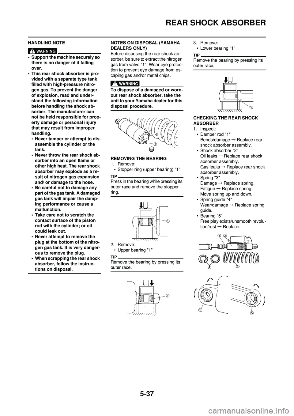
NOTES ON DISPOSAL (YAMAHA
DEALERS ONLY)
Before disposing the rear shock ab-
sorber, be sure to extract the nitrogen
gas from valve "1". Wear eye protec-
tion to prevent eye damage from es-
caping gas and/or metal chips.
To dispose of a damaged or worn-
out rear shock absorber, take the
unit to your Yamaha dealer for this
disposal procedure.
REMOVING THE BEARING
1. Remove:
• Stopper ring (upper bearing) "1"
Press in the bearing while pressing its
outer race and remove the stopper
ring.
2. Remove:• Upper bearing "1"
Remove the bearing by pressing its
outer race.
3. Remove:
• Lower bearing "1"
Remove the bearing by pressing its
outer race.
CHECKING THE REAR SHOCK
ABSORBER
1. Inspect:• Damper rod "1"
Bends/damage →Replace rear
shock absorber assembly.
• Shock absorber "2"
Oil leaks →Replace rear shock
absorber assembly.
Gas leaks →Replace rear shock
absorber assembly.
• Spring "3" Damage →Replace spring.
Fatigue →Replace spring.
Move spring up and down.
• Spring guide "4"
Wear/damage →Replace spring
guide.
• Bearing "5" Free play exists/unsmooth revolu-
tion/rust →Replace.
Page 175 of 196
5-38
REAR SHOCK ABSORBER
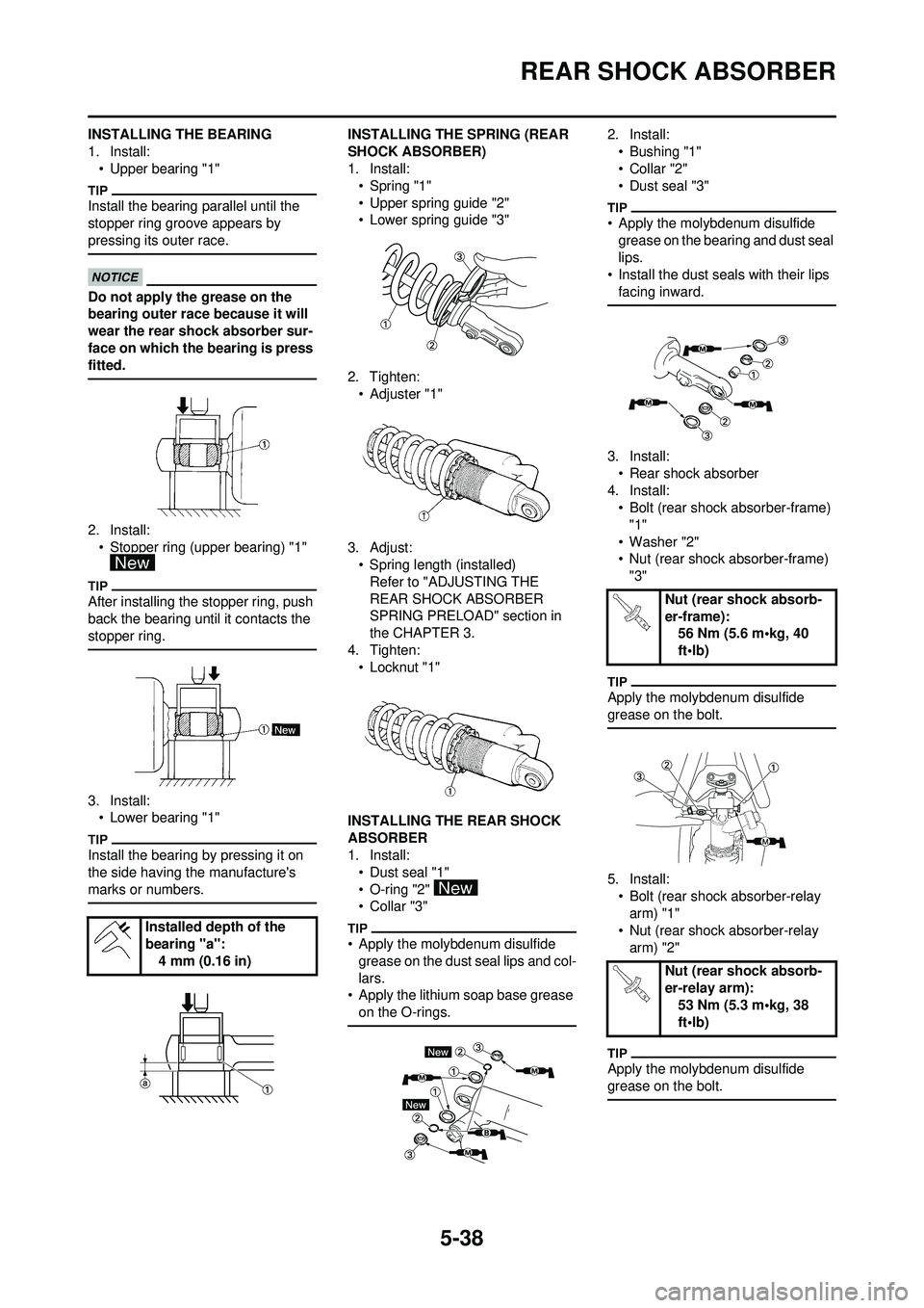
INSTALLING THE BEARING
1. Install:• Upper bearing "1"
Install the bearing parallel until the
stopper ring groove appears by
pressing its outer race.
Do not apply the grease on the
bearing outer race because it will
wear the rear shock absorber sur-
face on which the bearing is press
fitted.
2. Install:• Stopper ring (upper bearing) "1"
After installing the stopper ring, push
back the bearing until it contacts the
stopper ring.
3. Install: • Lower bearing "1"
Install the bearing by pressing it on
the side having the manufacture's
marks or numbers.
INSTALLING THE SPRING (REAR
SHOCK ABSORBER)
1. Install:• Spring "1"
• Upper spring guide "2"
• Lower spring guide "3"
2. Tighten: •Adjuster "1"
3. Adjust: • Spring length (installed)
Refer to "ADJUSTING THE
REAR SHOCK ABSORBER
SPRING PRELOAD" section in
the CHAPTER 3.
4. Tighten: • Locknut "1"
INSTALLING THE REAR SHOCK
ABSORBER
1. Install: • Dust seal "1"
• O-ring "2"
• Collar "3"
• Apply the molybdenum disulfide grease on the dust seal lips and col-
lars.
• Apply the lithium soap base grease on the O-rings.
2. Install:
• Bushing "1"
•Collar "2"
• Dust seal "3"
• Apply the molybdenum disulfide grease on the bearing and dust seal
lips.
• Install the dust seals with their lips
facing inward.
3. Install:• Rear shock absorber
4. Install: • Bolt (rear shock absorber-frame)
"1"
• Washer "2"
• Nut (rear shock absorber-frame) "3"
Apply the molybdenum disulfide
grease on the bolt.
5. Install:
• Bolt (rear shock absorber-relay arm) "1"
• Nut (rear shock absorber-relay
arm) "2"
Apply the molybdenum disulfide
grease on the bolt.
Installed depth of the
bearing "a": 4 mm (0.16 in)
Nut (rear shock absorb-
er-frame):56 Nm (5.6 m•kg, 40
ft•lb)
Nut (rear shock absorb-
er-relay arm): 53 Nm (5.3 m•kg, 38
ft•lb)
Page 176 of 196
![YAMAHA YZ250F 2010 Owners Manual 5-39
REAR SHOCK ABSORBER
6. Install:• Rear frame "1"
• Bolt [rear frame (upper)] "2"
• Bolt [rear frame (lower)] "3"
7. Tighten: • Bolt (air filter joint) "1" Bolt [rear frame (upper)]:
32 Nm YAMAHA YZ250F 2010 Owners Manual 5-39
REAR SHOCK ABSORBER
6. Install:• Rear frame "1"
• Bolt [rear frame (upper)] "2"
• Bolt [rear frame (lower)] "3"
7. Tighten: • Bolt (air filter joint) "1" Bolt [rear frame (upper)]:
32 Nm](/img/51/53945/w960_53945-175.png)
5-39
REAR SHOCK ABSORBER
6. Install:• Rear frame "1"
• Bolt [rear frame (upper)] "2"
• Bolt [rear frame (lower)] "3"
7. Tighten: • Bolt (air filter joint) "1" Bolt [rear frame (upper)]:
32 Nm (3.2 m•kg, 23
ft•lb)
Bolt [rear frame (lower)]: 32 Nm (3.2 m•kg, 23
ft•lb)
Bolt (air filter joint): 3 Nm (0.3 m•kg, 2.2
ft•lb)
Page 177 of 196
6-1
ELECTRICAL
This section is intended for those who have basic knowledge and skill concerning the servicing of Yamaha motorcycles
(e.g., Yamaha dealers, service engineers, etc.) Those who have little knowledge and skill concerning servicing are request-
ed not to undertake inspection, adjustment, disassembly, or reassembly only by reference to this manual. It may lead to
servicing trouble and mechanical damage.
6
Page 178 of 196
6-2
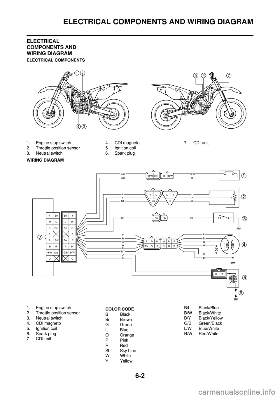
ELECTRICAL COMPONENTS AND WIRING DIAGRAM
ELECTRICAL
COMPONENTS AND
WIRING DIAGRAM
ELECTRICAL COMPONENTS
1. Engine stop switch
2. Throttle position sensor
3. Neutral switch4. CDI magneto
5. Ignition coil
6. Spark plug 7. CDI unit
WIRING DIAGRAM
1. Engine stop switch
2. Throttle position sensor
3. Neutral switch
4. CDI magneto
5. Ignition coil
6. Spark plug
7. CDI unit COLOR CODE
BBlack
Br Brown
GGreen
LBlue
O Orange
PPink
RRed
Sb Sky blue
WWhite
YYellow B/L Black/Blue
B/W Black/White
B/Y Black/Yellow
G/B Green/Black
L/W Blue/White
R/W Red/White
B/WB/W
B/L
B/Y
SbSb
G/B
LYLY
P
B
B
B
B
G
O
WR
P
GW
R
P
B
Br W
W
B/Y G Br
G
RR
OB
Sb Sb
Y
Y
W Y
W
GG B
P P
Br BrRR
O L
B
Sb Y
LL
B/L
B/W
B/W
G/B
B
B
B/L
L
Sb
B/L
G/B
G/B B/Y
B/Y
B/W O
B/W
BrBrP
Page 179 of 196
6-3
IGNITION SYSTEM
IGNITION SYSTEM
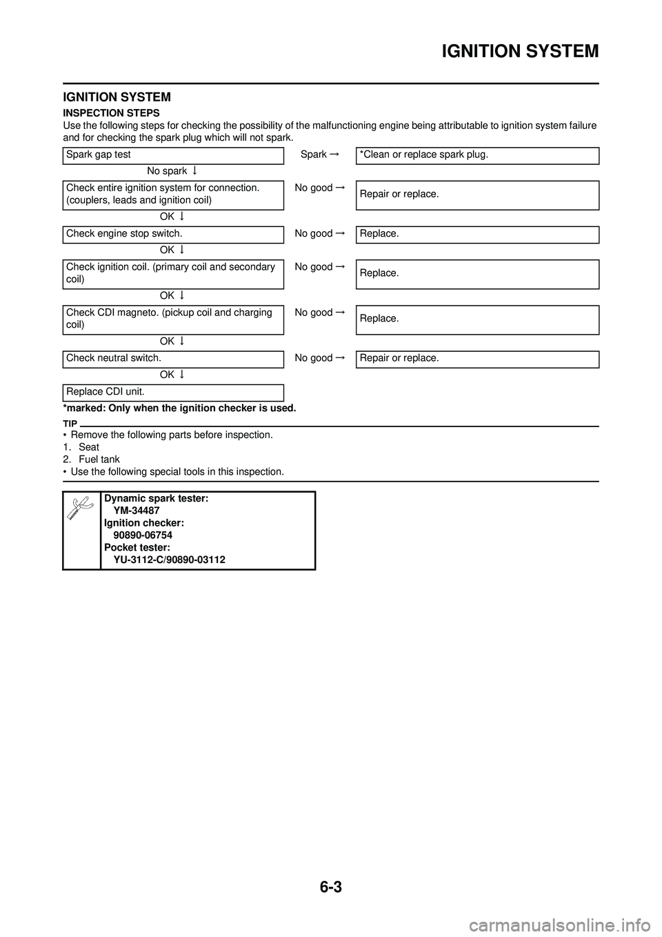
INSPECTION STEPS
Use the following steps for checking the possibility of the malfunctioning engine being attributable to ignition system failure
and for checking the spark plug which will not spark.
*marked: Only when the ignition checker is used.
• Remove the following parts before inspection.
1. Seat
2. Fuel tank
• Use the following special tools in this inspection.
Spark gap test Spark→ *Clean or replace spark plug.
No spark ↓
Check entire ignition system for connection.
(couplers, leads and ignition coil) No good
→
Repair or replace.
OK ↓
Check engine stop switch. No good→Replace.
OK ↓
Check ignition coil. (primary coil and secondary
coil) No good
→
Replace.
OK ↓
Check CDI magneto. (pickup coil and charging
coil) No good
→
Replace.
OK ↓
Check neutral switch. No good→Repair or replace.
OK ↓
Replace CDI unit.
Dynamic spark tester: YM-34487
Ignition checker:
90890-06754
Pocket tester:
YU-3112-C/90890-03112
Page 180 of 196
6-4
IGNITION SYSTEM
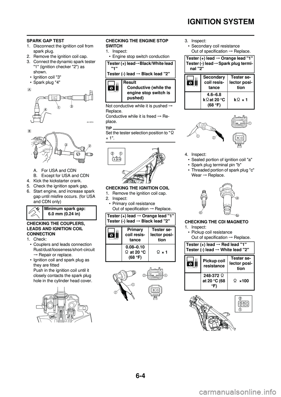
SPARK GAP TEST
1. Disconnect the ignition coil from spark plug.
2. Remove the ignition coil cap.
3. Connect the dynamic spark tester "1" (ignition ch ecker "2") as
shown.
• Ignition coil "3"
• Spark plug "4"
A. For USA and CDN
B. Except for USA and CDN
4. Kick the kickstarter crank.
5. Check the ignition spark gap.
6. Start engine, and increase spark gap until misfire occurs. (for USA
and CDN only)
CHECKING THE COUPLERS,
LEADS AND IGNITION COIL
CONNECTION
1. Check: • Couplers and leads connection
Rust/dust/looseness/short-circuit
→ Repair or replace.
• Ignition coil and spark plug as
they are fitted
Push in the ignition coil until it
closely contacts the spark plug
hole in the cylinder head cover. CHECKING THE ENGINE STOP
SWITCH
1. Inspect:
• Engine stop switch conduction
Not conductive while it is pushed →
Replace.
Conductive while it is freed →Re-
place.
Set the tester selection position to " Ω
× 1".
CHECKING THE IGNITION COIL
1. Remove the ignition coil cap.
2. Inspect: • Primary coil resistance
Out of specification →Replace. 3. Inspect:
• Secondary coil resistanceOut of specification →Replace.
4. Inspect: • Sealed portion of ignition coil "a"
• Spark plug terminal pin "b"
• Threaded portion of spark plug "c"Wear →Replace.
CHECKING THE CDI MAGNETO
1. Inspect: • Pickup coil resistance
Out of specification →Replace.
Minimum spark gap:
6.0 mm (0.24 in)
Tester (+) lead →Black/White lead
"1"
Tester (-) lead →Black lead "2"
Result Conductive (while the
engine stop switch is
pushed)
Tester (+) lead →Orange lead "1"
Tester (-) lead →Black lead "2"
Primary
coil resis-
tance Tester se-
lector posi-
tion
0.08–0.10
Ω at 20 °C (68 °F) Ω × 1
/W
BB
Tester (+) lead →Orange lead "1"
Tester (-) lead →Spark plug termi-
nal "2"
Secondary coil resis- tance Tester se-
lector posi- tion
4.6–6.8
k Ωat 20 °C
(68 °F) k
Ω × 1
Tester (+) lead →Red lead "1"
Tester (-) lead →White lead "2"
Pickup coil resistance Tester se-
lector posi-
tion
248-372 Ω
at 20 °C (68 °F) Ω
×100
B
WBr
G P
R