width YAMAHA YZ250F 2010 User Guide
[x] Cancel search | Manufacturer: YAMAHA, Model Year: 2010, Model line: YZ250F, Model: YAMAHA YZ250F 2010Pages: 196, PDF Size: 13.74 MB
Page 110 of 196

4-36
OIL FILTER ELEMENT AND WATER PUMP
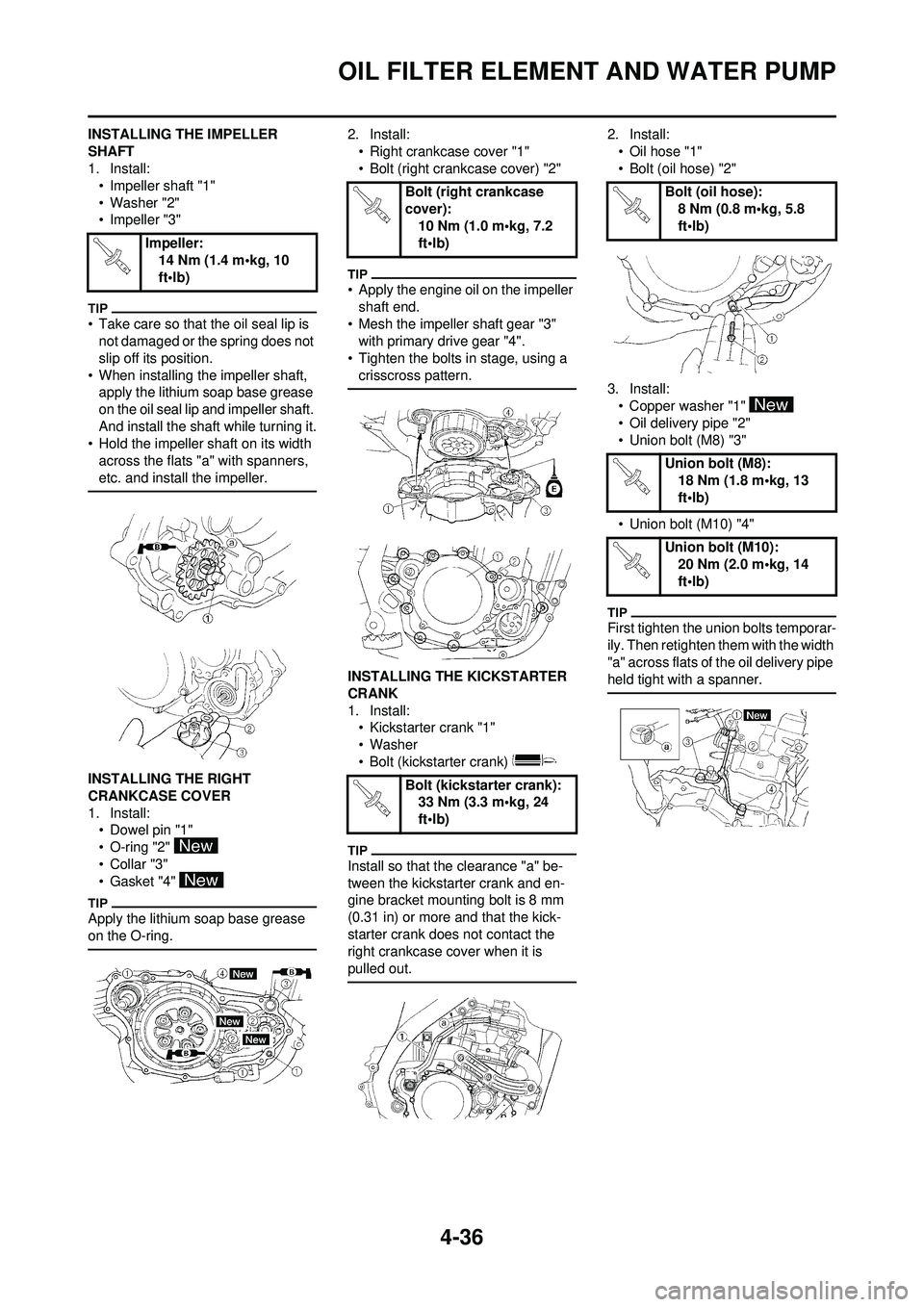
INSTALLING THE IMPELLER
SHAFT
1. Install:• Impeller shaft "1"
• Washer "2"
• Impeller "3"
• Take care so that the oil seal lip is not damaged or the spring does not
slip off its position.
• When installing the impeller shaft, apply the lithium soap base grease
on the oil seal lip and impeller shaft.
And install the shaft while turning it.
• Hold the impeller shaft on its width across the flats "a" with spanners,
etc. and install the impeller.
INSTALLING THE RIGHT
CRANKCASE COVER
1. Install:• Dowel pin "1"
• O-ring "2"
•Collar "3"
• Gasket "4"
Apply the lithium soap base grease
on the O-ring.
2. Install:
• Right crankcase cover "1"
• Bolt (right crankcase cover) "2"
• Apply the engine oil on the impeller shaft end.
• Mesh the impeller shaft gear "3" with primary drive gear "4".
• Tighten the bolts in stage, using a
crisscross pattern.
INSTALLING THE KICKSTARTER
CRANK
1. Install:• Kickstarter crank "1"
• Washer
• Bolt (kickstarter crank)
Install so that the clearance "a" be-
tween the kickstarter crank and en-
gine bracket mounting bolt is 8 mm
(0.31 in) or more and that the kick-
starter crank does not contact the
right crankcase cover when it is
pulled out.
2. Install:
• Oil hose "1"
• Bolt (oil hose) "2"
3. Install: • Copper washer "1"
• Oil delivery pipe "2"
• Union bolt (M8) "3"
• Union bolt (M10) "4"
First tighten the union bolts temporar-
ily. Then retighten them with the width
"a" across flats of the oil delivery pipe
held tight with a spanner.
Impeller: 14 Nm (1.4 m•kg, 10
ft•lb)
Bolt (right crankcase
cover):
10 Nm (1.0 m•kg, 7.2
ft•lb)
Bolt (kickstarter crank): 33 Nm (3.3 m•kg, 24
ft•lb)Bolt (oil hose): 8 Nm (0.8 m•kg, 5.8
ft•lb)
Union bolt (M8): 18 Nm (1.8 m•kg, 13
ft•lb)
Union bolt (M10): 20 Nm (2.0 m•kg, 14
ft•lb)
Page 132 of 196

4-58
CRANKCASE AND CRANKSHAFT
DISASSEMBLING THE
CRANKCASE
1. Separate:• Right crankcase
• Left crankcase
Separation steps:
a. Remove the crankcase bolts "1", hose guide "2" and clutch cable
holder "3".
Loosen each bolt 1/4 of a turn at a
time and after all the bolts are loos-
ened, remove them.
b. Remove the right crankcase "4".
• Place the crankcase with its left half
downward and split the right half
apart while lifting it horizontally by
lightly tapping the projection "a" on
it using a soft hammer.
• When splitting it, leave the crank-
shaft and transmission with the left
half.
Use soft hammer to tap on the
case half. Tap only on reinforced
portions of case. Do not tap on
gasket mating surface. Work slow-
ly and carefully. Make sure the
case halves separate evenly. If the
cases do not separate, check for a
remaining case bolt or fitting. Do
not force.
c. Remove the dowel pins and O- ring.
REMOVING THE CRANKSHAFT
1. Remove:• Crankshaft "1"Use the crankcase separating
tool "2".
Do not use a hammer to drive out
the crankshaft.
REMOVING THE CRANKCASE
BEARING
1. Remove:
•Bearing "1"
• Remove the bearing from the crankcase by pressing its inner
race.
• Do not use the removed bearing.
CHECKING THE TIMING CHAIN
AND TIMING CHAIN GUIDE
1. Inspect: • Timing chainCracks/stiff →Replace the timing
chain and camshaft sprocket as a
set.
2. Inspect: • Timing chain guideWear/damage →Replace. CHECKING THE CRANKCASE
1. Inspect:
• Contacting surface "a"Scratches →Replace.
• Engine mounting boss "b", crank- case
Cracks/damage →Replace.
2. Inspect: • BearingRotate inner race with a finger.
Rough spot/seizure →Replace.
3. Inspect: • Oil sealDamage →Replace.
CHECKING THE CRANKSHAFT
1. Measure: • Runout limit "a"
• Small end free play limit "b"
• Connecting rod big end side clearance "c"
• Crank width "d" Out of specification →Replace.
Use the dial gauge and a thick-
ness gauge.
Crankcase separating
tool: YU-1135-A/90890-
01135
Dial gauge and stand: YU-3097/90890-01252
Standard
Runo
ut lim-
it: 0.03 mm (0.0012
in) 0.05
mm
(0.002 in)
Small
end
free
play: 0.4–1.0 mm
(0.016–0.039 in) 2.0 mm
(0.08 in)
Side
clear-
ance: 0.15–0.45 mm
(0.0059–0.0177 in) 0.50
mm
(0.02 in)
Crack
width: 55.95–56.00
mm
(2.203–2.205 in) —