check engine YAMAHA YZ250F 2010 Owner's Manual
[x] Cancel search | Manufacturer: YAMAHA, Model Year: 2010, Model line: YZ250F, Model: YAMAHA YZ250F 2010Pages: 196, PDF Size: 13.74 MB
Page 80 of 196
4-6
RADIATOR
HANDLING NOTE
Do not remove the radiator cap
when the engine and radiator are
hot. Scalding hot fluid and steam
may be blown out under pressure,
which could cause serious injury.
When the engine has cooled, open
the radiator cap by the following
procedure:
Place a thick rag, like a towel, over
the radiator cap, slowly rotate the
cap counterclockwise to the de-
tent. This procedure allows any re-
sidual pressure to escape. When
the hissing sound has stopped,
press down on the cap while turn-
ing counterclockwise and remove
it.
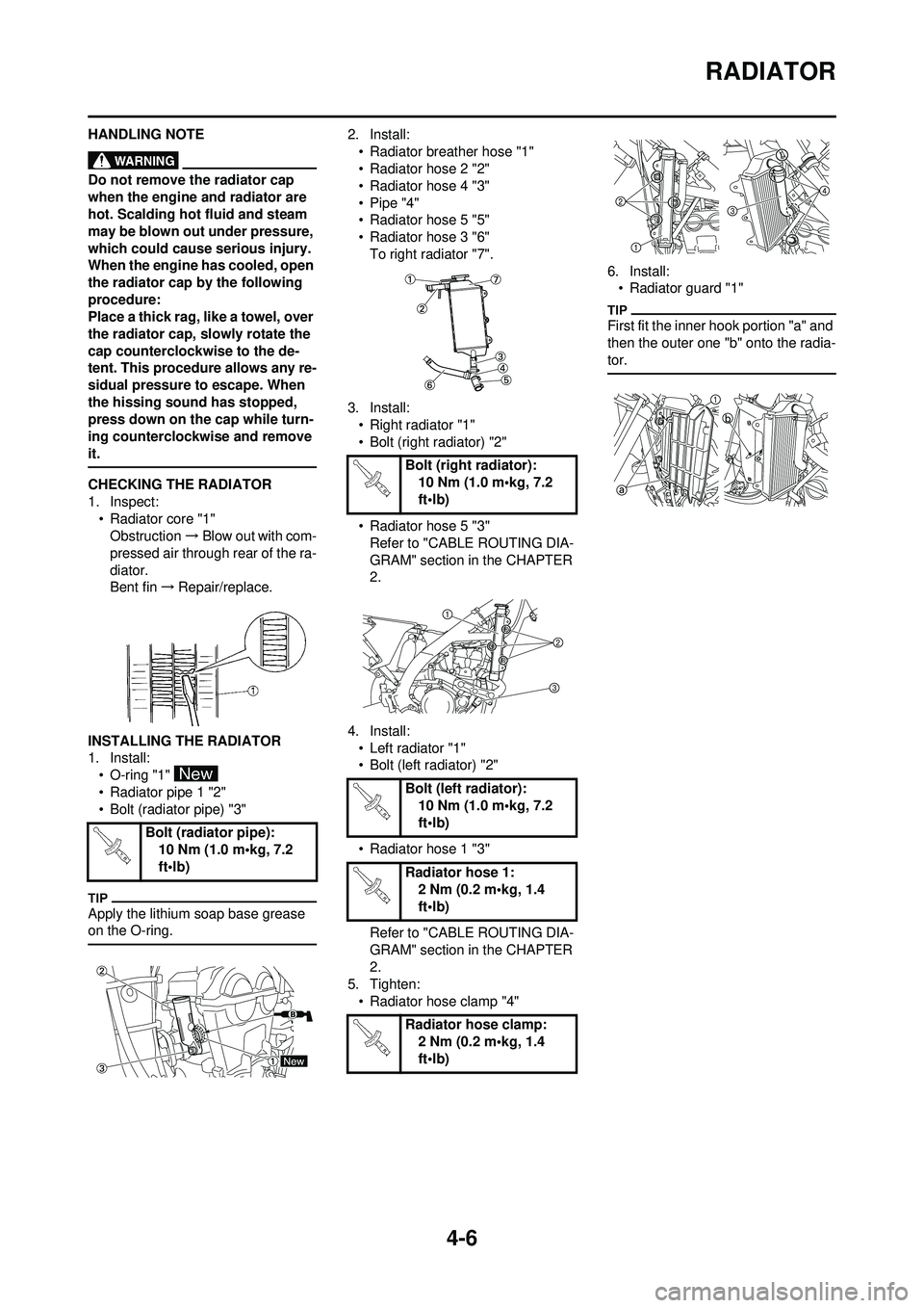
CHECKING THE RADIATOR
1. Inspect:• Radiator core "1"
Obstruction →Blow out with com-
pressed air through rear of the ra-
diator.
Bent fin →Repair/replace.
INSTALLING THE RADIATOR
1. Install: • O-ring "1"
• Radiator pipe 1 "2"
• Bolt (radiator pipe) "3"
Apply the lithium soap base grease
on the O-ring.
2. Install:• Radiator breather hose "1"
• Radiator hose 2 "2"
• Radiator hose 4 "3"
• Pipe "4"
• Radiator hose 5 "5"
• Radiator hose 3 "6"To right radiator "7".
3. Install: • Right radiator "1"
• Bolt (right radiator) "2"
• Radiator hose 5 "3"
Refer to "CABLE ROUTING DIA-
GRAM" section in the CHAPTER
2.
4. Install: • Left radiator "1"
• Bolt (left radiator) "2"
• Radiator hose 1 "3"
Refer to "CABLE ROUTING DIA-
GRAM" section in the CHAPTER
2.
5. Tighten:
• Radiator hose clamp "4" 6. Install:
• Radiator guard "1"
First fit the inner hook portion "a" and
then the outer one "b" onto the radia-
tor.
Bolt (radiator pipe):
10 Nm (1.0 m•kg, 7.2
ft•lb)
Bolt (right radiator):10 Nm (1.0 m•kg, 7.2
ft•lb)
Bolt (left radiator): 10 Nm (1.0 m•kg, 7.2
ft•lb)
Radiator hose 1: 2 Nm (0.2 m•kg, 1.4
ft•lb)
Radiator hose clamp: 2 Nm (0.2 m•kg, 1.4
ft•lb)
Page 84 of 196
4-10
CARBURETOR
HANDLING NOTE
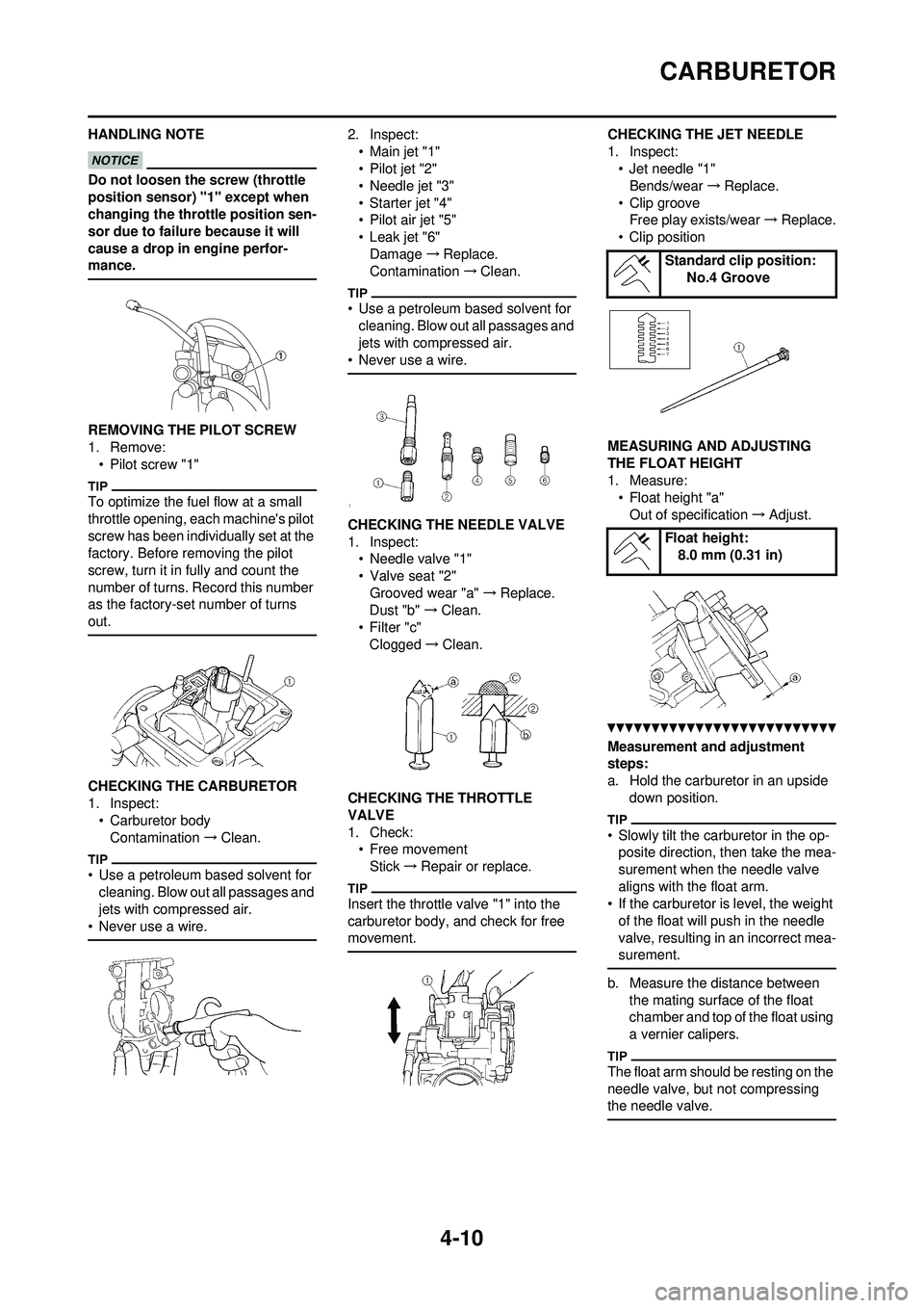
Do not loosen the screw (throttle
position sensor) "1" except when
changing the throttle position sen-
sor due to failure because it will
cause a drop in engine perfor-
mance.
REMOVING THE PILOT SCREW
1. Remove: • Pilot screw "1"
To optimize the fuel flow at a small
throttle opening, each machine's pilot
screw has been individually set at the
factory. Before removing the pilot
screw, turn it in fully and count the
number of turns. Record this number
as the factory-set number of turns
out.
CHECKING THE CARBURETOR
1. Inspect:
• Carburetor bodyContamination →Clean.
• Use a petroleum based solvent for
cleaning. Blow out all passages and
jets with compressed air.
• Never use a wire.
2. Inspect:
•Main jet "1"
• Pilot jet "2"
• Needle jet "3"
• Starter jet "4"
•Pilot air jet "5"
• Leak jet "6"Damage →Replace.
Contamination →Clean.
• Use a petroleum based solvent for
cleaning. Blow out all passages and
jets with compressed air.
• Never use a wire.
CHECKING THE NEEDLE VALVE
1. Inspect: • Needle valve "1"
• Valve seat "2"
Grooved wear "a" →Replace.
Dust "b" →Clean.
• Filter "c"
Clogged →Clean.
CHECKING THE THROTTLE
VALVE
1. Check: • Free movementStick →Repair or replace.
Insert the throttle valve "1" into the
carburetor body, and check for free
movement.
CHECKING THE JET NEEDLE
1. Inspect: • Jet needle "1"Bends/wear →Replace.
• Clip groove Free play exists/wear →Replace.
• Clip position
MEASURING AND ADJUSTING
THE FLOAT HEIGHT
1. Measure: • Float height "a"Out of specification →Adjust.
Measurement and adjustment
steps:
a. Hold the carburetor in an upside
down position.
• Slowly tilt the ca rburetor in the op-
posite direction, then take the mea-
surement when the needle valve
aligns with the float arm.
• If the carburetor is level, the weight of the float will push in the needle
valve, resulting in an incorrect mea-
surement.
b. Measure the distance between the mating surface of the float
chamber and top of the float using
a vernier calipers.
The float arm should be resting on the
needle valve, but not compressing
the needle valve.
Standard clip position: No.4 Groove
Float height: 8.0 mm (0.31 in)
Page 91 of 196

4-17
CAMSHAFTS
4. Measure:• Camshaft-to-cap clearanceOut of specification →Measure
camshaft outside diameter.
Measurement steps:
a. Install the camshaft onto the cylin- der head.
b. Position a strip of Plastigauge
®
"1" onto the camshaft.
c. Install the clip, dowel pins and camshaft caps.
• Tighten the bolts (camshaft cap) in a crisscross pattern from innermost
to outer caps.
• Do not turn the camshaft when
measuring clearance with the
Plastigauge
®.
d. Remove the camshaft caps and measure the width of the Plasti-
gauge
® "1".
5. Measure:• Camshaft outside diameter "a"
Out of specification →Replace the
camshaft.
Within specification →Replace
camshaft case and camshaft
caps as a set. CHECKING THE CAMSHAFT
SPROCKET
1. Inspect:
• Camshaft sprocket "1"Wear/damage →Replace the
camshaft assemb ly and timing
chain as a set.
CHECKING THE
DECOMPRESSION SYSTEM
1. Check: • Decompression system
Checking steps:
a. Check that the decompression
mechanism cam "1" moves
smoothly.
b. Check that the decompression
mechanism cam lever pin "2" proj-
ects from the camshaft.
CHECKING THE TIMING CHAIN
TENSIONER
1. Check:• While pressing the tensioner rod lightly with fingers, use a thin
screwdriver "1" and wind the ten-
sioner rod up fully clockwise.
• When releasing the screwdriver
by pressing lightly with fingers,
make sure that the tensioner rod
will come out smoothly.
• If not, replace the tensioner as- sembly. INSTALLING THE CAMSHAFT
1. Install:
• Exhaust camshaft "1"
• Intake camshaft "2"
Installation steps:
a. Turn the crankshaft counterclock- wise with a wrench.
• Apply the molybdenum disulfide oil on the camshafts.
• Apply the engine oil on the decom- pression system.
• Squeezing the decompression le-
ver allows the crankshaft to be
turned easily.
b. Align the T.D.C. mark "a" on the rotor with the align mark "b" on the
crankcase cover when piston is at
T.D.C. on compression stroke.
Camshaft-to-cap clear-
ance:
0.028–0.062 mm
(0.0011–0.0024 in)
in)
Bolt (camshaft cap): 10 Nm (1.0 m•kg, 7.2
ft•lb)
Camshaft outside diame-
ter: 21.959–21.972 mm
(0.8645–0.8650 in)
Page 98 of 196

4-24
VALVES AND VALVE SPRINGS
CHECKING THE VALVE SPRINGS
1. Measure:• Valve spring free length "a"Out of specification →Replace.
2. Measure: • Compressed spring force "a"Out of specification →Replace.
b. Installed length
3. Measure: • Spring tilt "a"Out of specification →Replace. CHECKING THE
VALVE LIFTERS
1. Inspect:
• Valve lifterScratches/damage →Replace
both lifters and cylinder head.
INSTALLING THE VALVES
1. Apply: • Molybdenum disulfide oil
Onto the valve stem and valve
stem seal.
2. Install:
• Valve "1"
• Valve spring seat "2"
• Valve stem seal "3"
• Valve spring "4"
• Valve spring retainer "5"To cylinder head.
• Make sure that each valve is in-
stalled in its original place, also re-
ferring to the painted color as
follows.
Intake (middle) "a": Sky blue
Intake (right/left) "b": not paint
Exhaust "c": Purple
• Install the valve springs with the larger pitch "d" facing upward.
e. Smaller pitch 3. Install:
• Valve cotter
While compressing the valve spring
with a valve spring compressor "1" in-
stall the valve cotters.
4. To secure the valve cotters onto the valve stem, lightly tap the
valve tip with a piece of wood.
Hitting the valve tip with excessive
force could damage the valve.
5. Install:• Adjusting pad "1"
• Valve lifter "2"
• Apply the molybdenum disulfide oil on the valve stem end.
• Apply the engine oil on the valve lift-
ers.
• Valve lifter must turn smoothly when rotated with a finger.
• Be careful to reinstall valve lifters and pads in their original place.
Free length (valve
spring): Intake:39.76 mm (1.57 in)
(1.53 in)
Exhaust:
37.78 mm (1.49 in)
(1.45 in)
Compressed spring
force: Intake:99–114 N at 28.98 mm
(9.9–11.4 kg at 28.98
mm, 22.27–25.57 lb at
1.14 in)
Exhaust: 126–145 N at 28.30
mm (12.6–14.5 kg at
28.30 mm,
28.44–31.97 lb at 1.11
in)
Spring tilt limit: Intake:2.5°/1.7 mm (0.067 in)
Exhaust:
2.5°/1.6 mm (0.063 in)
Valve spring compres-
sor: YM-4019/90890-04019
Page 101 of 196
4-27
CYLINDER AND PISTON
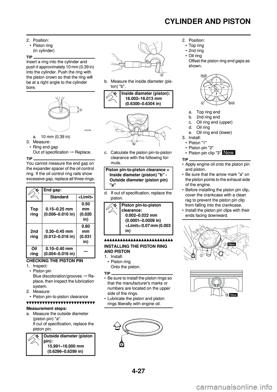
2. Position:• Piston ring(in cylinder)
Insert a ring into the cylinder and
push it approximately 10 mm (0.39 in)
into the cylinder. Push the ring with
the piston crown so that the ring will
be at a right angle to the cylinder
bore.
a. 10 mm (0.39 in)
3. Measure:
• Ring end gapOut of specification →Replace.
You cannot measure the end gap on
the expander spacer of the oil control
ring. If the oil control ring rails show
excessive gap, replace all three rings.
CHECKING THE PISTON PIN
1. Inspect:
• Piston pinBlue discoloration/grooves →Re-
place, then inspect the lubrication
system.
2. Measure:
• Piston pin-to-piston clearance
Measurement steps:
a. Measure the outside diameter (piston pin) "a".
If out of specification, replace the
piston pin. b. Measure the inside diameter (pis-
ton) "b".
c. Calculate the piston pin-to-piston clearance with the following for-
mula.
d. If out of specific ation, replace the
piston.
INSTALLING THE PISTON RING
AND PISTON
1. Install: •Piston ring
Onto the piston.
• Be sure to install the piston rings so that the manufacturer's marks or
numbers are located on the upper
side of the rings.
• Lubricate the piston and piston rings liberally with engine oil.
2. Position:
•Top ring
•2nd ring
•Oil ringOffset the piston ring end gaps as
shown.
a. Top ring end
b. 2nd ring end
c. Oil ring end (upper)
d. Oil ring
e. Oil ring end (lower)
3. Install: • Piston "1"
• Piston pin "2"
• Piston pin clip "3"
• Apply engine oil onto the piston pin and piston.
• Be sure that the arrow mark "a" on
the piston points to the exhaust side
of the engine.
• Before installing the piston pin clip,
cover the crankcase with a clean
rag to prevent the piston pin clip
from falling into the crankcase.
• Install the piston pin clips with their ends facing downward.
End gap:
Standard
Top
ring 0.15–0.25 mm
(0.006–0.010 in) 0.50
mm
(0.020 in)
2nd
ring 0.30–0.45 mm
(0.012–0.018 in) 0.80
mm
(0.031 in)
Oil
ring 0.10–0.40 mm
(0.004–0.016 in) —
Outside diameter (piston
pin): 15.991–16.000 mm
(0.6296–0.6299 in)
Inside diameter (piston):
16.002–16.013 mm
(0.6300–0.6304 in)
Piston pin-to-pis ton clearance =
Inside diameter (piston) "b" -
Outside diameter (piston pin)
"a"
Piston pin-to-piston
clearance:0.002–0.022 mm
(0.0001–0.0009 in)
in)
New
Page 105 of 196
4-31
CLUTCH
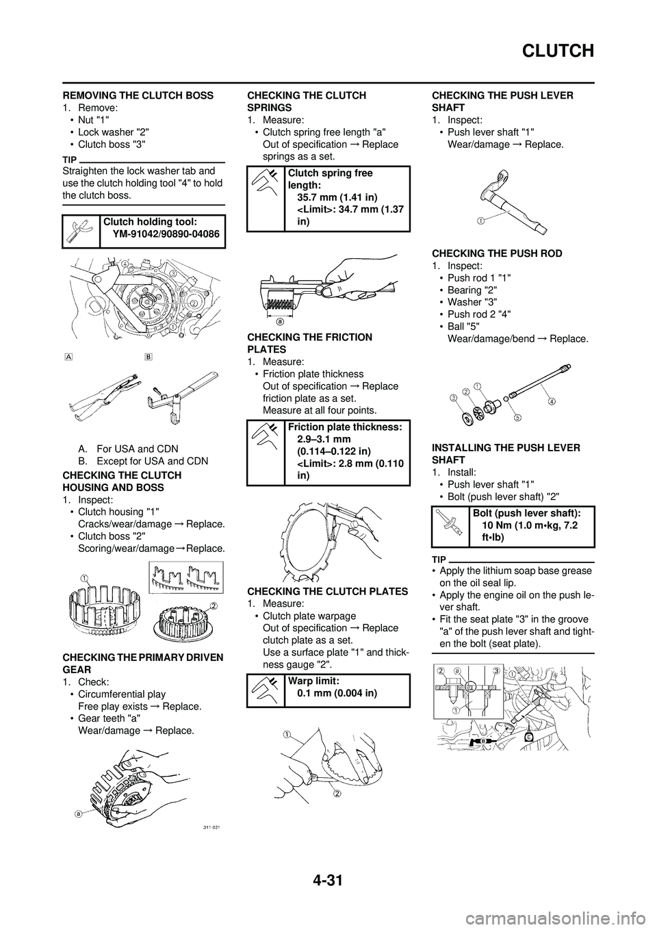
REMOVING THE CLUTCH BOSS
1. Remove:•Nut "1"
• Lock washer "2"
• Clutch boss "3"
Straighten the lock washer tab and
use the clutch holding tool "4" to hold
the clutch boss.
A. For USA and CDN
B. Except for USA and CDN
CHECKING THE CLUTCH
HOUSING AND BOSS
1. Inspect: • Clutch housing "1"
Cracks/wear/damage →Replace.
• Clutch boss "2" Scoring/wear/damage →Replace.
CHECKING THE PRIMARY DRIVEN
GEAR
1. Check: • Circumferential play
Free play exists →Replace.
• Gear teeth "a" Wear/damage →Replace. CHECKING THE CLUTCH
SPRINGS
1. Measure:
• Clutch spring free length "a"
Out of specification →Replace
springs as a set.
CHECKING THE FRICTION
PLATES
1. Measure: • Friction plate thickness
Out of specification →Replace
friction plate as a set.
Measure at all four points.
CHECKING THE CLUTCH PLATES
1. Measure: • Clutch plate warpageOut of specification →Replace
clutch plate as a set.
Use a surface plate "1" and thick-
ness gauge "2". CHECKING THE PUSH LEVER
SHAFT
1. Inspect:
• Push lever shaft "1"
Wear/damage →Replace.
CHECKING THE PUSH ROD
1. Inspect: • Push rod 1 "1"
• Bearing "2"
• Washer "3"
• Push rod 2 "4"
•Ball "5"Wear/damage/bend →Replace.
INSTALLING THE PUSH LEVER
SHAFT
1. Install: • Push lever shaft "1"
• Bolt (push lever shaft) "2"
• Apply the lithium soap base grease
on the oil seal lip.
• Apply the engine oil on the push le- ver shaft.
• Fit the seat plate "3" in the groove "a" of the push lever shaft and tight-
en the bolt (seat plate).
Clutch holding tool: YM-91042/90890-04086
Clutch spring free
length:
35.7 mm (1.41 in)
in)
Friction plate thickness: 2.9–3.1 mm
(0.114–0.122 in)
in)
Warp limit: 0.1 mm (0.004 in)
Bolt (push lever shaft): 10 Nm (1.0 m•kg, 7.2
ft•lb)
Page 113 of 196
4-39
BALANCER
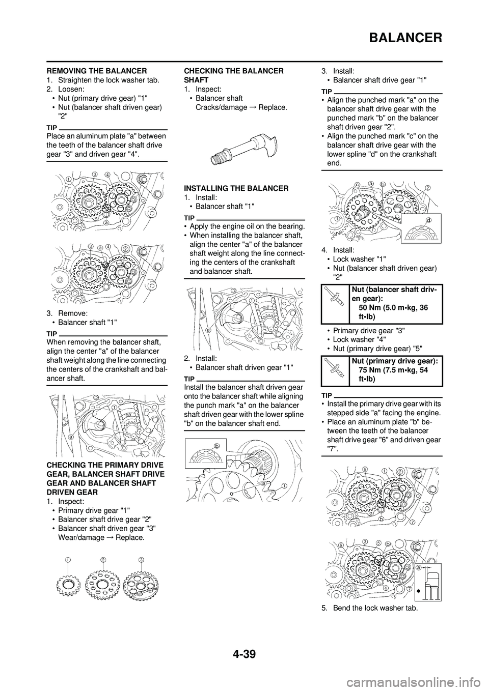
REMOVING THE BALANCER
1. Straighten the lock washer tab.
2. Loosen:• Nut (primary drive gear) "1"
• Nut (balancer shaft driven gear) "2"
Place an aluminum plate "a" between
the teeth of the balancer shaft drive
gear "3" and driven gear "4".
3. Remove:• Balancer shaft "1"
When removing the balancer shaft,
align the center "a" of the balancer
shaft weight along the line connecting
the centers of the crankshaft and bal-
ancer shaft.
CHECKING THE PRIMARY DRIVE
GEAR, BALANCER SHAFT DRIVE
GEAR AND BALANCER SHAFT
DRIVEN GEAR
1. Inspect:
• Primary drive gear "1"
• Balancer shaft drive gear "2"
• Balancer shaft driven gear "3"Wear/damage →Replace. CHECKING THE BALANCER
SHAFT
1. Inspect:
• Balancer shaft
Cracks/damage →Replace.
INSTALLING THE BALANCER
1. Install: • Balancer shaft "1"
• Apply the engine oil on the bearing.
• When installing the balancer shaft, align the center "a" of the balancer
shaft weight along the line connect-
ing the centers of the crankshaft
and balancer shaft.
2. Install:• Balancer shaft driven gear "1"
Install the balancer shaft driven gear
onto the balancer shaft while aligning
the punch mark "a" on the balancer
shaft driven gear with the lower spline
"b" on the balancer shaft end.
3. Install:
• Balancer shaft drive gear "1"
• Align the punched mark "a" on the balancer shaft drive gear with the
punched mark "b" on the balancer
shaft driven gear "2".
• Align the punched mark "c" on the balancer shaft drive gear with the
lower spline "d" on the crankshaft
end.
4. Install:
• Lock washer "1"
• Nut (balancer shaft driven gear) "2"
• Primary drive gear "3"
• Lock washer "4"
• Nut (primary drive gear) "5"
• Install the primary drive gear with its stepped side "a" facing the engine.
• Place an aluminum plate "b" be- tween the teeth of the balancer
shaft drive gear "6" and driven gear
"7".
5. Bend the lock washer tab.
Nut (balancer shaft driv-
en gear): 50 Nm (5.0 m•kg, 36
ft•lb)
Nut (primary drive gear): 75 Nm (7.5 m•kg, 54
ft•lb)
Page 116 of 196
4-42
OIL PUMP
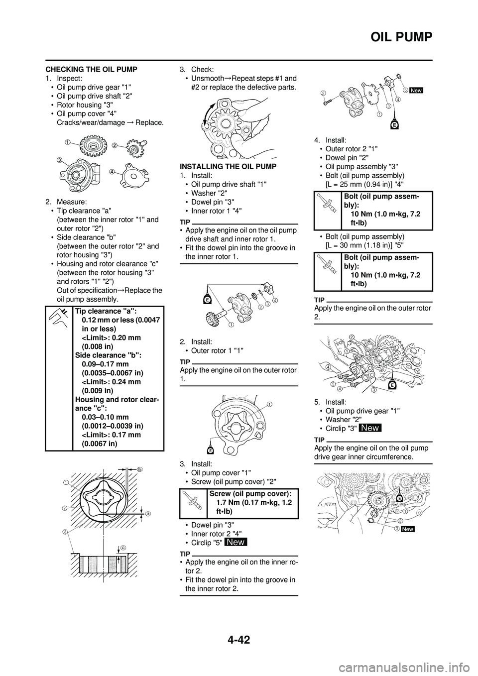
CHECKING THE OIL PUMP
1. Inspect:• Oil pump drive gear "1"
• Oil pump drive shaft "2"
• Rotor housing "3"
• Oil pump cover "4"Cracks/wear/damage →Replace.
2. Measure: • Tip clearance "a"(between the inner rotor "1" and
outer rotor "2")
• Side clearance "b" (between the outer rotor "2" and
rotor housing "3")
• Housing and rotor clearance "c" (between the rotor housing "3"
and rotors "1" "2")
Out of specification →Replace the
oil pump assembly. 3. Check:
• Unsmooth →Repeat steps #1 and
#2 or replace the defective parts.
INSTALLING THE OIL PUMP
1. Install: • Oil pump drive shaft "1"
• Washer "2"
• Dowel pin "3"
• Inner rotor 1 "4"
• Apply the engine oil on the oil pump drive shaft and inner rotor 1.
• Fit the dowel pin into the groove in
the inner rotor 1.
2. Install:• Outer rotor 1 "1"
Apply the engine oil on the outer rotor
1.
3. Install:• Oil pump cover "1"
• Screw (oil pump cover) "2"
• Dowel pin "3"
• Inner rotor 2 "4"
• Circlip "5"
• Apply the engine oil on the inner ro-tor 2.
• Fit the dowel pin into the groove in
the inner rotor 2.
4. Install:• Outer rotor 2 "1"
• Dowel pin "2"
• Oil pump assembly "3"
• Bolt (oil pump assembly)
[L = 25 mm (0.94 in)] "4"
• Bolt (oil pump assembly) [L = 30 mm (1.18 in)] "5"
Apply the engine oil on the outer rotor
2.
5. Install:
• Oil pump drive gear "1"
• Washer "2"
• Circlip "3"
Apply the engine oil on the oil pump
drive gear inner circumference.
Tip clearance "a": 0.12 mm or less (0.0047
in or less)
(0.008 in)
Side clearance "b": 0.09–0.17 mm
(0.0035–0.0067 in)
(0.009 in)
Housing and rotor clear-
ance "c": 0.03–0.10 mm
(0.0012–0.0039 in)
(0.0067 in)
Screw (oil pump cover):1.7 Nm (0.17 m•kg, 1.2
ft•lb)
Bolt (oil pump assem-
bly): 10 Nm (1.0 m•kg, 7.2
ft•lb)
Bolt (oil pump assem-
bly): 10 Nm (1.0 m•kg, 7.2
ft•lb)
Page 132 of 196

4-58
CRANKCASE AND CRANKSHAFT
DISASSEMBLING THE
CRANKCASE
1. Separate:• Right crankcase
• Left crankcase
Separation steps:
a. Remove the crankcase bolts "1", hose guide "2" and clutch cable
holder "3".
Loosen each bolt 1/4 of a turn at a
time and after all the bolts are loos-
ened, remove them.
b. Remove the right crankcase "4".
• Place the crankcase with its left half
downward and split the right half
apart while lifting it horizontally by
lightly tapping the projection "a" on
it using a soft hammer.
• When splitting it, leave the crank-
shaft and transmission with the left
half.
Use soft hammer to tap on the
case half. Tap only on reinforced
portions of case. Do not tap on
gasket mating surface. Work slow-
ly and carefully. Make sure the
case halves separate evenly. If the
cases do not separate, check for a
remaining case bolt or fitting. Do
not force.
c. Remove the dowel pins and O- ring.
REMOVING THE CRANKSHAFT
1. Remove:• Crankshaft "1"Use the crankcase separating
tool "2".
Do not use a hammer to drive out
the crankshaft.
REMOVING THE CRANKCASE
BEARING
1. Remove:
•Bearing "1"
• Remove the bearing from the crankcase by pressing its inner
race.
• Do not use the removed bearing.
CHECKING THE TIMING CHAIN
AND TIMING CHAIN GUIDE
1. Inspect: • Timing chainCracks/stiff →Replace the timing
chain and camshaft sprocket as a
set.
2. Inspect: • Timing chain guideWear/damage →Replace. CHECKING THE CRANKCASE
1. Inspect:
• Contacting surface "a"Scratches →Replace.
• Engine mounting boss "b", crank- case
Cracks/damage →Replace.
2. Inspect: • BearingRotate inner race with a finger.
Rough spot/seizure →Replace.
3. Inspect: • Oil sealDamage →Replace.
CHECKING THE CRANKSHAFT
1. Measure: • Runout limit "a"
• Small end free play limit "b"
• Connecting rod big end side clearance "c"
• Crank width "d" Out of specification →Replace.
Use the dial gauge and a thick-
ness gauge.
Crankcase separating
tool: YU-1135-A/90890-
01135
Dial gauge and stand: YU-3097/90890-01252
Standard
Runo
ut lim-
it: 0.03 mm (0.0012
in) 0.05
mm
(0.002 in)
Small
end
free
play: 0.4–1.0 mm
(0.016–0.039 in) 2.0 mm
(0.08 in)
Side
clear-
ance: 0.15–0.45 mm
(0.0059–0.0177 in) 0.50
mm
(0.02 in)
Crack
width: 55.95–56.00
mm
(2.203–2.205 in) —
Page 134 of 196

4-60
CRANKCASE AND CRANKSHAFT
5. Install:• Dowel pin "1"
• O-ring "2"
• Right crankcaseTo left crankcase.
• Apply the lithium soap base grease
on the O-ring.
• Fit the right crankcase onto the left crankcase. Tap lightly on the case
with soft hammer.
• When installing the crankcase, the connecting rod should be posi-
tioned at TDC (top dead center).
6. Tighten:
• Hose guide "1"
• Clutch cable holder "2"
• Bolt (crankcase) "3"
Tighten the crankcase tightening
bolts in stage, using a crisscross pat-
tern.
7. Install:• Oil delivery pipe 2 "1"
• O-ring "2"
• Bolt (oil delivery pipe 2) "3"
Apply the lithium soap base grease
on the Orings.
8. Install:• Timing chain "1"
• Timing chain guide (intake side)
"2"
• Bolt (timing chain guide) "3"
9. Remove: • Sealant
Forced out on the cylinder mating
surface.
10. Apply:
• Engine oilTo the crank pin, bearing and oil
delivery hole.
11. Check: • Crankshaft and transmission op-eration.
Unsmooth operation →Repair.
Bolt (crankcase):
12 Nm (1.2 m•kg, 8.7
ft•lb)
Bolt (oil delivery pipe 2): 10 Nm (1.0 m•kg, 7.2
ft•lb)
Bolt (timing chain guide):10 Nm (1.0 m•kg, 7.2
ft•lb)