YAMAHA YZ250F 2010 Service Manual
Manufacturer: YAMAHA, Model Year: 2010, Model line: YZ250F, Model: YAMAHA YZ250F 2010Pages: 196, PDF Size: 13.74 MB
Page 41 of 196
2-15
TIGHTENING TORQUES
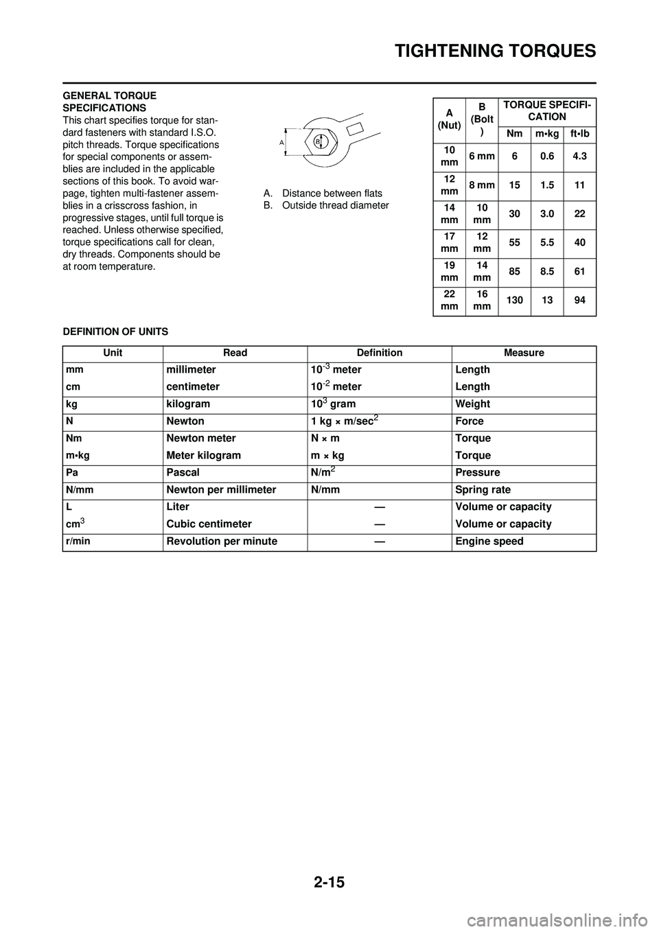
GENERAL TORQUE
SPECIFICATIONS
This chart specifies torque for stan-
dard fasteners with standard I.S.O.
pitch threads. Torque specifications
for special components or assem-
blies are included in the applicable
sections of this book. To avoid war-
page, tighten multi-fastener assem-
blies in a crisscross fashion, in
progressive stages, until full torque is
reached. Unless otherwise specified,
torque specifications call for clean,
dry threads. Components should be
at room temperature.A. Distance between flats
B. Outside thread diameter
DEFINITION OF UNITS
A
(Nut) B
(Bolt
) TORQUE SPECIFI-
CATION
Nm m•kg ft•lb
10
mm 6 mm 6 0.6 4.3
12
mm 8 mm 15 1.5 11
14
mm 10
mm 30 3.0 22
17
mm 12
mm 55 5.5 40
19
mm 14
mm 85 8.5 61
22
mm 16
mm 130 13 94
Unit
Read Definition Measure
mm
millimeter 10-3 meterLength
cmcentimeter 10-2 meterLength
kgkilogram 103 gramWeight
NNewton 1 kg × m/sec2Force
NmNewton meter N × mTorque
m•kgMeter kilogram m × kg Torque
PaPascalN/m2Pressure
N/mmNewton per millimeter N/mm Spring rate
LLiter—Volume or capacity
cm3Cubic centimeter —Volume or capacity
r/minRevolution per minute —Engine speed
Page 42 of 196
2-16
LUBRICATION DIAGRAMS
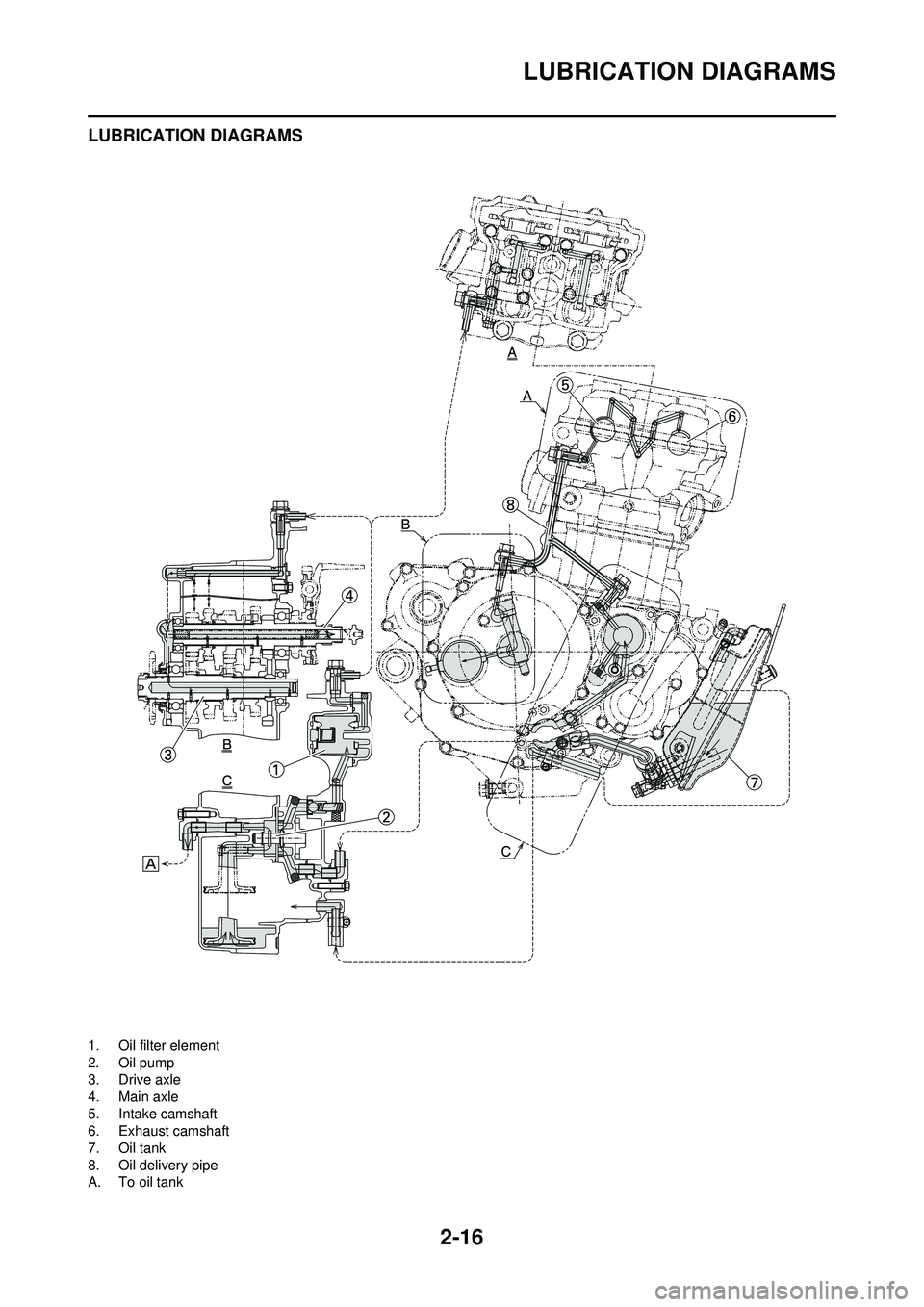
LUBRICATION DIAGRAMS
1. Oil filter element
2. Oil pump
3. Drive axle
4. Main axle
5. Intake camshaft
6. Exhaust camshaft
7. Oil tank
8. Oil delivery pipe
A. To oil tank
Page 43 of 196
2-17
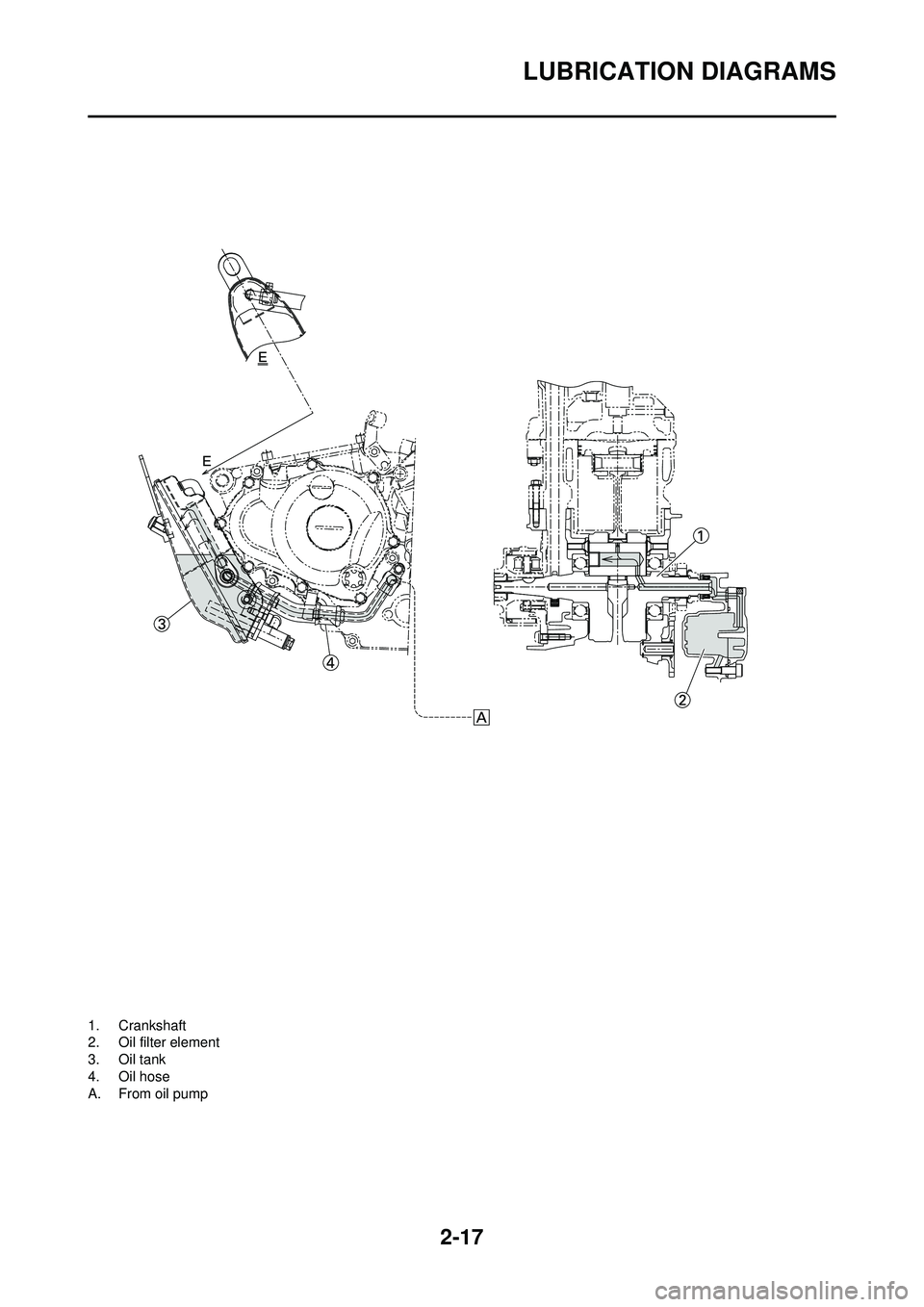
LUBRICATION DIAGRAMS
1. Crankshaft
2. Oil filter element
3. Oil tank
4. Oil hose
A. From oil pump
Page 44 of 196
2-18
CABLE ROUTING DIAGRAM
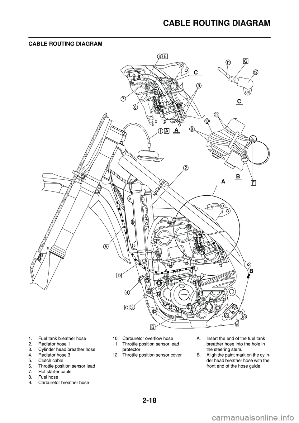
CABLE ROUTING DIAGRAM
1. Fuel tank breather hose
2. Radiator hose 1
3. Cylinder head breather hose
4. Radiator hose 3
5. Clutch cable
6. Throttle position sensor lead
7. Hot starter cable
8. Fuel hose
9. Carburetor breather hose10. Carburetor overflow hose
11. Throttle position sensor lead
protector
12. Throttle position sensor cover A. Insert the end of the fuel tank
breather hose into the hole in
the steering stem.
B. Aligh the paint mark on the cylin- der head breather hose with the
front end of the hose guide.
A
B
A C
B
C
Page 45 of 196
2-19
CABLE ROUTING DIAGRAM
C. Pass the cylinder head breather hose on the outside of front en-
gine bracket.
D. Pass the cylinder head breather
hose between the radiator and
radiator hose 3.
E. Pass the fuel hose on the out-
side of throttle position sensor
lead.
F. Pass the carburetor breather
hoses and overflow hose so that
all there hoses do not contact
the rear shock absorber.
G. Insert the throttle position sen- sor lead protector into the throt-
tle position sensor cover.
Page 46 of 196
2-20
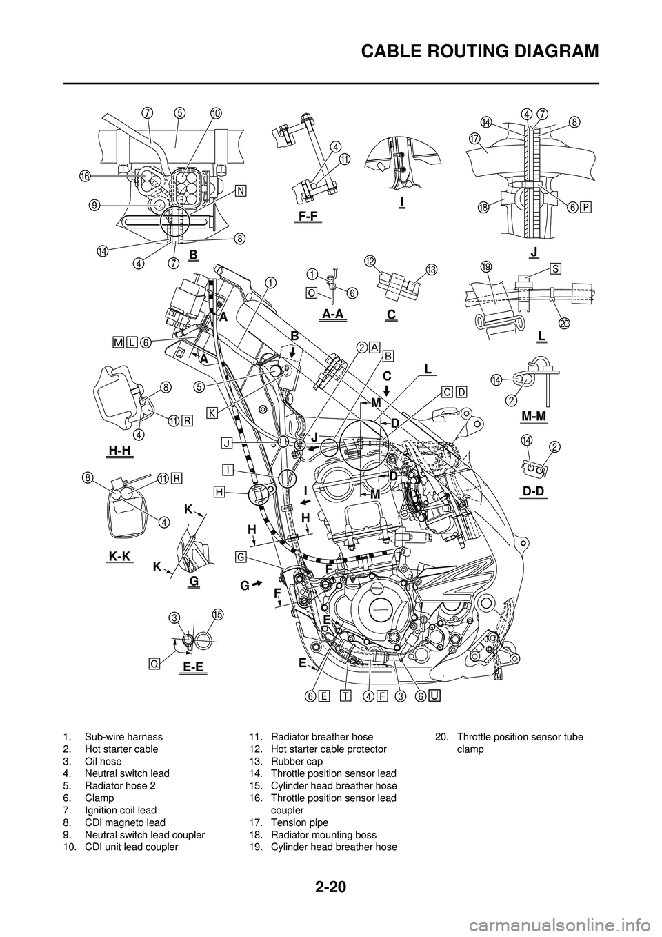
CABLE ROUTING DIAGRAM
1. Sub-wire harness
2. Hot starter cable
3. Oil hose
4. Neutral switch lead
5. Radiator hose 2
6. Clamp
7. Ignition coil lead
8. CDI magneto lead
9. Neutral switch lead coupler
10. CDI unit lead coupler11. Radiator breather hose
12. Hot starter cable protector
13. Rubber cap
14. Throttle position sensor lead
15. Cylinder head breather hose
16. Throttle position sensor lead
coupler
17. Tension pipe
18. Radiator mounting boss
19. Cylinder head breather hose 20. Throttle position sensor tube
clamp
E
K
E
F
G H
H
F
I
J
A
A B
D
D
C J
C
G
B
K
E
M
M
H-H
K-K
E-E
D-D
M-M
F-F
A-A
I
L
L
Page 47 of 196
2-21
CABLE ROUTING DIAGRAM
A. Pass the hot starter cable over the radiator mounting boss.
B. Pass the throttle position sensor lead under the hot starter cable.
C. Fasten the throttle position sen- sor lead and the hot starter ca-
ble.
D. Locate the clamp between the hot starter cable protector and
rubber cap.
E. Fasten the neutral switch lead below the oil hose. and pass the
neutral switch lead on the inside
of the oil hose.
F. Pass the neutral switch lead on the inside of the oil hose.
G. Fasten the neutral switch lead, CDI magneto lead, and radiator
breather hose onto the frame.
They should all be clamped
above the engine bracket to the
left of the downtube of the
frame. The clamp ends should
face backward and the rest out-
side of the frame.
H. Pass the clutch cable through the cable guide.
I. Pass the neutral switch lead and
CDI magneto lead behind the
frame.
J. Pass the hot starter cable on the
inside of the cylinder head
breather hose.
K. Fit the coupler projection into the
hole in the cover.
L. Fasten the sub-wire harness on the CDI unit bracket.
M. Fasten the sub-wire harness at the position-taped portion.
N. Pass each lead under the clamp. Locate the CDI magneto
lead on the outside of the igni-
tion coil lead. Locate the throttle
position sensor lead, neutral
switch lead, CDI magneto lead
and ignition coil lead so that they
do not lie one on another.
O. Fasten the sub-wire harness to
the CDI unit bracket with the
clamp ends located under the
bracket.
P. Fasten the neutral switch lead, throttle position sensor lead,
CDI magneto lead and ignition
coil lead. Fasten them around
the periphery of the recess be-
tween the tension pipe and radi-
ator mounting boss on the
frame.
Q. Locate the clamp ends within
the arrowed range. Assure that
the clamp end does not contact
the cylinder head breather hose. R. Pass the radiator breather hose
on the outside of the CDI mag-
neto lead and neutral switch
lead.
S. Fasten the throttle position sen- sor lead and hot starter cable.
Fasten them between the cylin-
der head breather hose and
throttle position sensor tube
clamp. Fasten the clamp with its
ends toward the right-side of the
frame and cut off the other end
with 3 to 5 clamp holes left in it.
T. Locate the radiator breather hose end above the down tube
and between the oil hose and
engine guard.
U. Fasten the neutral switch lead above the oil hose, and pass the
neutral switch lead on the inside
of the oil hose.
Page 48 of 196
2-22
CABLE ROUTING DIAGRAM
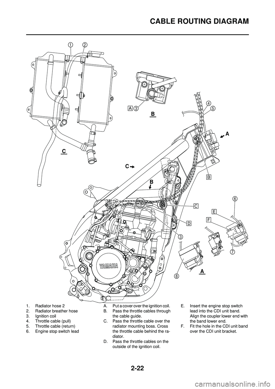
1. Radiator hose 2
2. Radiator breather hose
3. Ignition coil
4. Throttle cable (pull)
5. Throttle cable (return)
6. Engine stop switch leadA. Put a cover over the ignition coil.
B. Pass the throttle cables through
the cable guide.
C. Pass the throttle cable over the radiator mounting boss. Cross
the throttle cable behind the ra-
diator.
D. Pass the throttle cables on the
outside of the ignition coil. E. Insert the engine stop switch
lead into the CDI unit band.
Align the coupler lower end with
the band lower end.
F. Fit the hole in the CDI unit band
over the CDI unit bracket.
C A
B B
A
C
Page 49 of 196
2-23
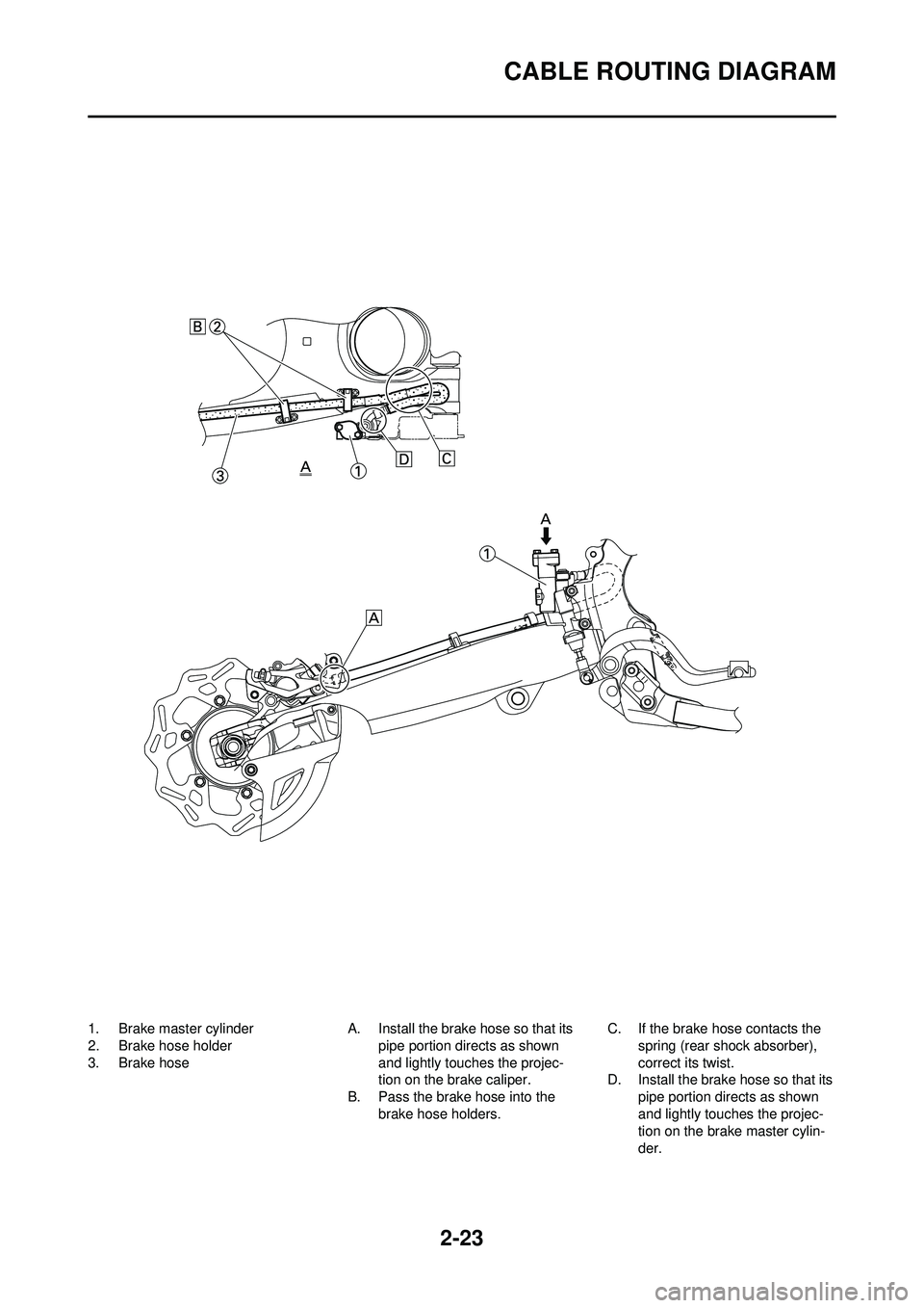
CABLE ROUTING DIAGRAM
1. Brake master cylinder
2. Brake hose holder
3. Brake hoseA. Install the brake hose so that its
pipe portion directs as shown
and lightly touches the projec-
tion on the brake caliper.
B. Pass the brake hose into the
brake hose holders. C. If the brake hose contacts the
spring (rear shock absorber),
correct its twist.
D. Install the brake hose so that its
pipe portion directs as shown
and lightly touches the projec-
tion on the brake master cylin-
der.
Page 50 of 196
2-24
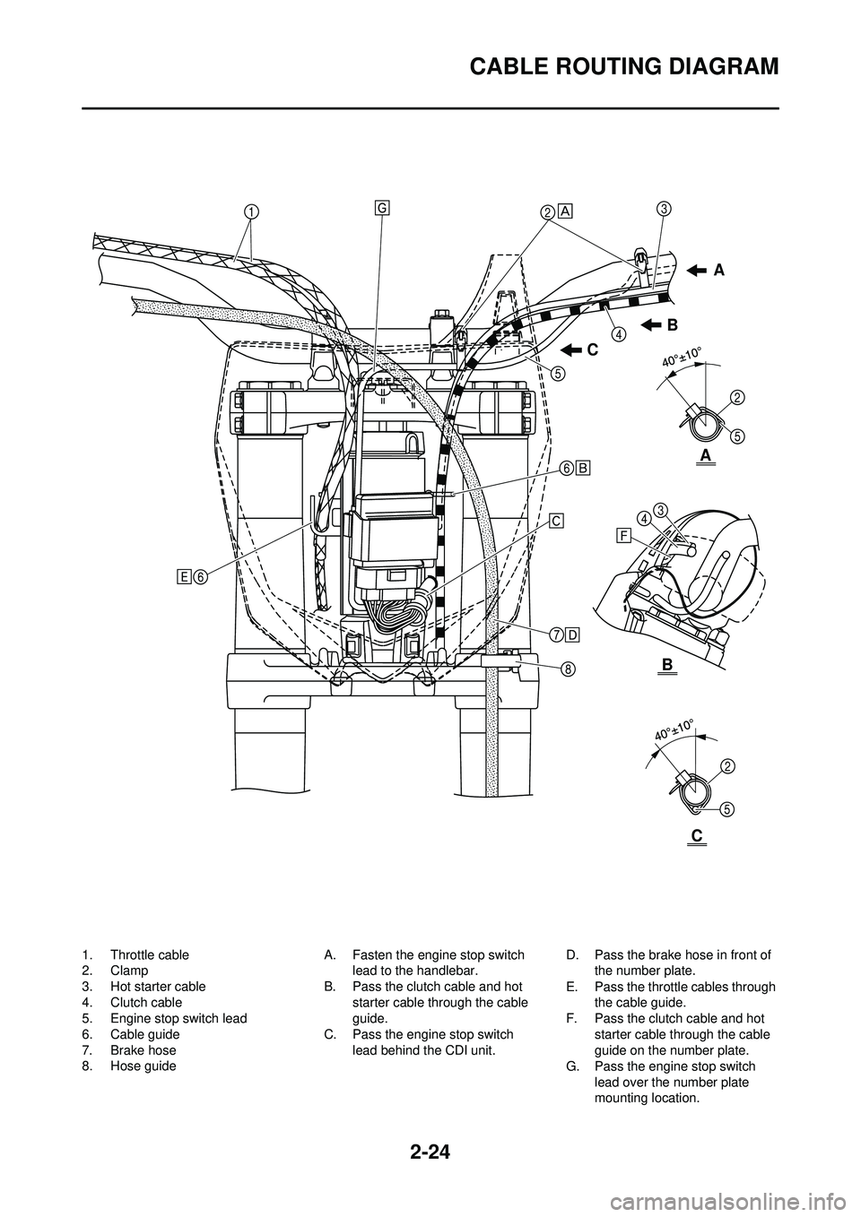
CABLE ROUTING DIAGRAM
1. Throttle cable
2. Clamp
3. Hot starter cable
4. Clutch cable
5. Engine stop switch lead
6. Cable guide
7. Brake hose
8. Hose guideA. Fasten the engine stop switch
lead to the handlebar.
B. Pass the clutch cable and hot starter cable through the cable
guide.
C. Pass the engine stop switch lead behind the CDI unit. D. Pass the brake hose in front of
the number plate.
E. Pass the throttle cables through the cable guide.
F. Pass the clutch cable and hot
starter cable through the cable
guide on the number plate.
G. Pass the engine stop switch
lead over the number plate
mounting location.
A
C B
C
B
A