air suspension YAMAHA YZ250F 2010 Owners Manual
[x] Cancel search | Manufacturer: YAMAHA, Model Year: 2010, Model line: YZ250F, Model: YAMAHA YZ250F 2010Pages: 196, PDF Size: 13.74 MB
Page 53 of 196

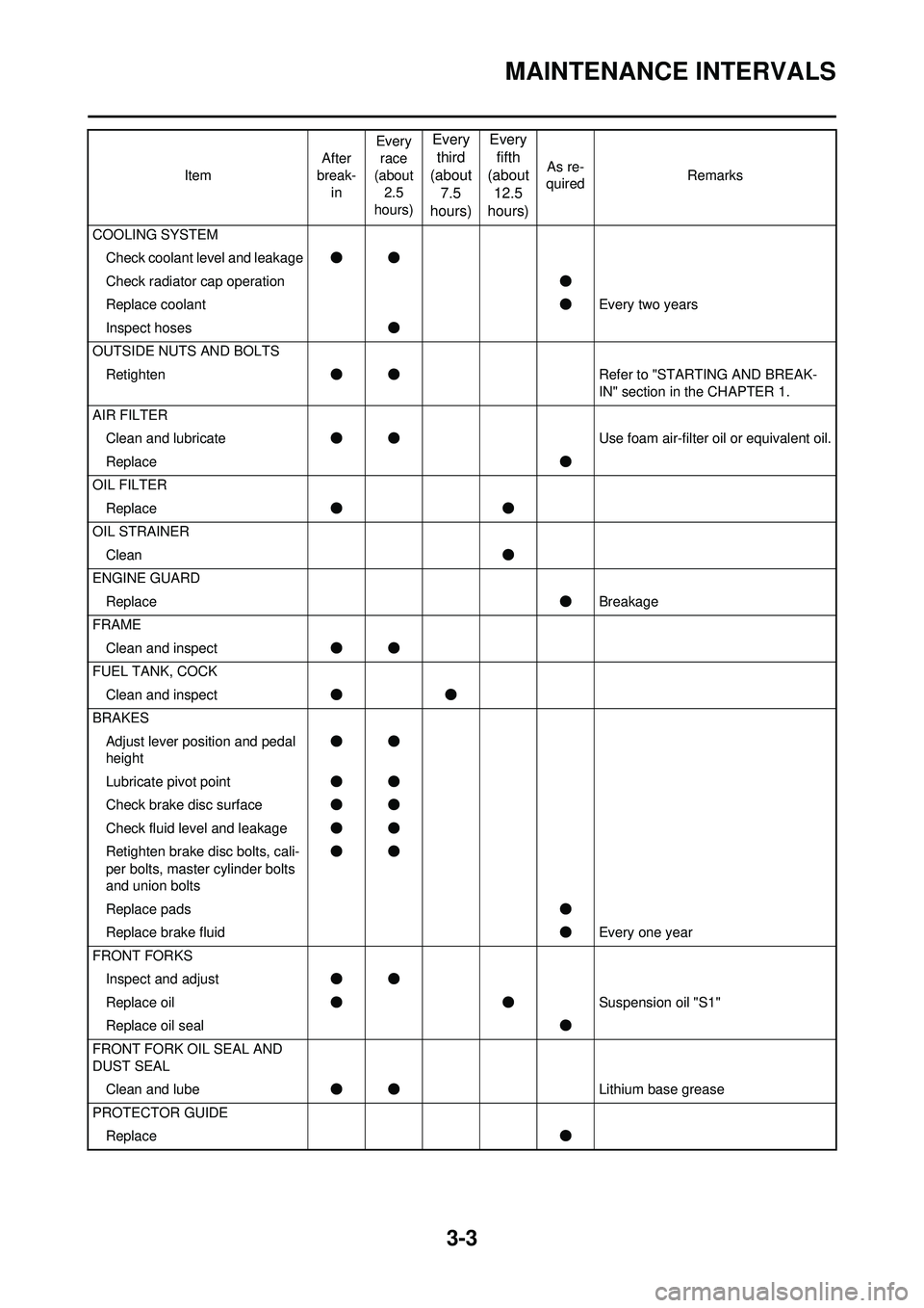
3-3
MAINTENANCE INTERVALS
COOLING SYSTEMCheck coolant level and leakage ●●
Check radiator cap operation ●
Replace coolant ●Every two years
Inspect hoses ●
OUTSIDE NUTS AND BOLTS Retighten ●● Refer to "STARTING AND BREAK-
IN" section in the CHAPTER 1.
AIR FILTER Clean and lubricate ●● Use foam air-filter oil or equivalent oil.
Replace ●
OIL FILTER Replace ●●
OIL STRAINER Clean ●
ENGINE GUARD Replace ●Breakage
FRAME Clean and inspect ●●
FUEL TANK, COCK Clean and inspect ●●
BRAKES Adjust lever position and pedal
height ●●
Lubricate pivot point ●●
Check brake disc surface ●●
Check fluid level and leakage ●●
Retighten brake disc bolts, cali-
per bolts, master cylinder bolts
and union bolts ●●
Replace pads ●
Replace brake fluid ●Every one year
FRONT FORKS Inspect and adjust ●●
Replace oil ●● Suspension oil "S1"
Replace oil seal ●
FRONT FORK OIL SEAL AND
DUST SEAL Clean and lube ●● Lithium base grease
PROTECTOR GUIDE Replace ●
Item
After
break- in Every
race
(about 2.5
hours)
Every third
(about 7.5
hours) Every
fifth
(about 12.5
hours)
As re-
quired Remarks
Page 156 of 196

5-19
FRONT FORK
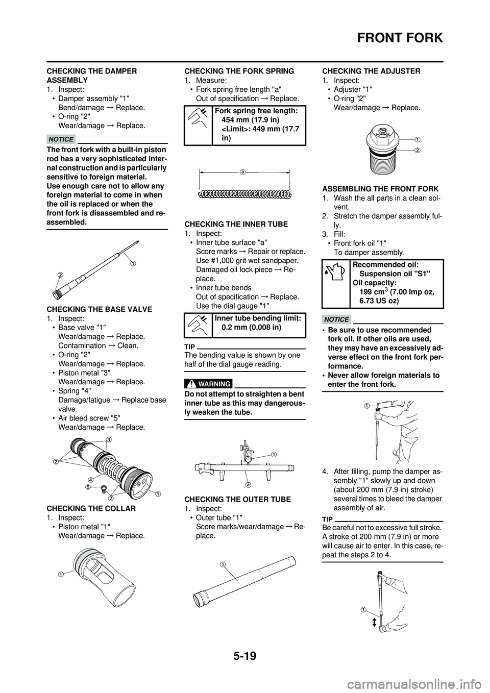
CHECKING THE DAMPER
ASSEMBLY
1. Inspect:• Damper assembly "1"
Bend/damage → Replace.
• O-ring "2" Wear/damage → Replace.
The front fork with a built-in piston
rod has a very sophisticated inter-
nal construction and is particularly
sensitive to foreign material.
Use enough care not to allow any
foreign material to come in when
the oil is replaced or when the
front fork is disassembled and re-
assembled.
CHECKING THE BASE VALVE
1. Inspect: • Base valve "1"
Wear/damage →Replace.
Contamination →Clean.
• O-ring "2"
Wear/damage →Replace.
• Piston metal "3" Wear/damage →Replace.
• Spring "4" Damage/fatigue →Replace base
valve.
• Air bleed screw "5" Wear/damage →Replace.
CHECKING THE COLLAR
1. Inspect: • Piston metal "1"Wear/damage →Replace. CHECKING THE FORK SPRING
1. Measure:
• Fork spring free length "a"Out of specification →Replace.
CHECKING THE INNER TUBE
1. Inspect: • Inner tube surface "a"Score marks →Repair or replace.
Use #1,000 grit wet sandpaper.
Damaged oil lock piece →Re-
place.
• Inner tube bends Out of specification →Replace.
Use the dial gauge "1".
The bending value is shown by one
half of the dial gauge reading.
Do not attempt to straighten a bent
inner tube as this may dangerous-
ly weaken the tube.
CHECKING THE OUTER TUBE
1. Inspect:
• Outer tube "1"Score marks/wear/damage →Re-
place. CHECKING THE ADJUSTER
1. Inspect:
•Adjuster "1"
• O-ring "2"
Wear/damage →Replace.
ASSEMBLING THE FRONT FORK
1. Wash the all parts in a clean sol- vent.
2. Stretch the damper assembly ful- ly.
3. Fill:
• Front fork oil "1"To damper assembly.
• Be sure to use recommended fork oil. If other oils are used,
they may have an excessively ad-
verse effect on the front fork per-
formance.
• Never allow foreign materials to
enter the front fork.
4. After filling, pump the damper as- sembly "1" slowly up and down
(about 200 mm (7.9 in) stroke)
several times to bleed the damper
assembly of air.
Be careful not to ex cessive full stroke.
A stroke of 200 mm (7.9 in) or more
will cause air to enter. In this case, re-
peat the steps 2 to 4.
Fork spring free length: 454 mm (17.9 in)
in)
Inner tube bending limit: 0.2 mm (0.008 in)
Recommended oil: Suspension oil "S1"
Oil capacity: 199 cm
3 (7.00 Imp oz,
6.73 US oz)
Page 191 of 196

7-7
CHASSIS
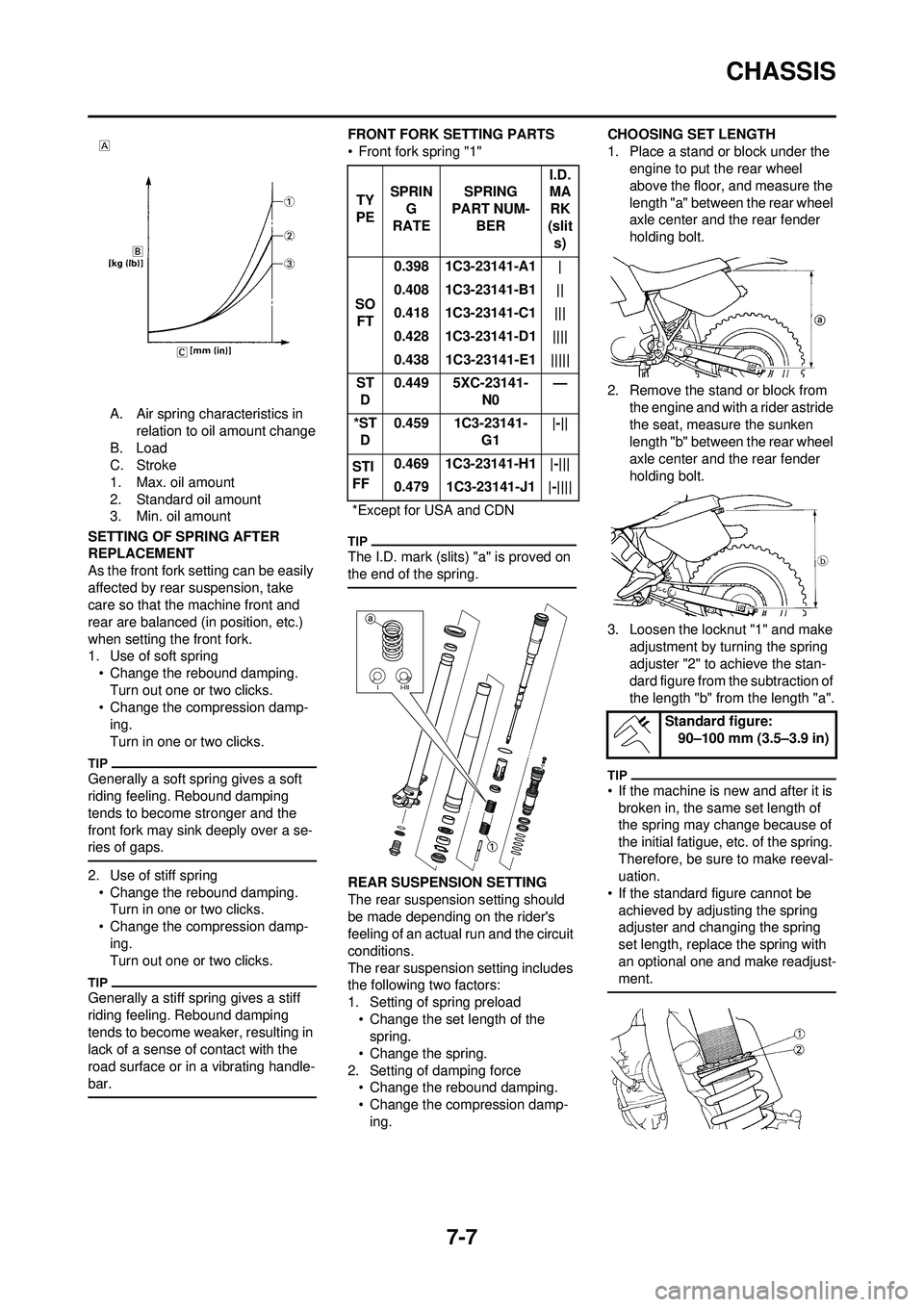
A. Air spring characteristics in relation to oil amount change
B. Load
C. Stroke
1. Max. oil amount
2. Standard oil amount
3. Min. oil amount
SETTING OF SPRING AFTER
REPLACEMENT
As the front fork setting can be easily
affected by rear suspension, take
care so that the machine front and
rear are balanced (in position, etc.)
when setting the front fork.
1. Use of soft spring • Change the rebound damping.
Turn out one or two clicks.
• Change the compression damp- ing.
Turn in one or two clicks.
Generally a soft spring gives a soft
riding feeling. Rebound damping
tends to become stronger and the
front fork may sink deeply over a se-
ries of gaps.
2. Use of stiff spring• Change the rebound damping.Turn in one or two clicks.
• Change the compression damp- ing.
Turn out one or two clicks.
Generally a stiff spring gives a stiff
riding feeling. Rebound damping
tends to become weaker, resulting in
lack of a sense of contact with the
road surface or in a vibrating handle-
bar.
FRONT FORK SETTING PARTS
• Front fork spring "1"
The I.D. mark (slits) "a" is proved on
the end of the spring.
REAR SUSPENSION SETTING
The rear suspension setting should
be made depending on the rider's
feeling of an actual run and the circuit
conditions.
The rear suspension setting includes
the following two factors:
1. Setting of spring preload • Change the set length of the spring.
• Change the spring.
2. Setting of damping force • Change the rebound damping.
• Change the compression damp-ing. CHOOSING SET LENGTH
1. Place a stand or block under the
engine to put the rear wheel
above the floor, and measure the
length "a" between the rear wheel
axle center and the rear fender
holding bolt.
2. Remove the stand or block from the engine and with a rider astride
the seat, measure the sunken
length "b" between the rear wheel
axle center and the rear fender
holding bolt.
3. Loosen the locknut "1" and make adjustment by turning the spring
adjuster "2" to achieve the stan-
dard figure from the subtraction of
the length "b" from the length "a".
• If the machine is new and after it is broken in, the same set length of
the spring may change because of
the initial fatigue, etc. of the spring.
Therefore, be sure to make reeval-
uation.
• If the standard figure cannot be
achieved by adjusting the spring
adjuster and changing the spring
set length, replace the spring with
an optional one and make readjust-
ment.
TY
PE SPRIN
G
RATE SPRING
PART NUM-
BER I.D.
MA
RK
(slit s)
SO FT 0.398 1C3-23141-A1 |
0.408 1C3-23141-B1 ||
0.418 1C3-23141-C1 |||
0.428 1C3-23141-D1 ||||
0.438 1C3-23141-E1 |||||
ST D 0.449 5XC-23141-
N0—
*ST D 0.459 1C3-23141-
G1|-||
STI
FF 0.469 1C3-23141-H1 |-|||
0.479 1C3-23141-J1 |-||||
*Except for USA and CDN
Standard figure: 90–100 mm (3.5–3.9 in)