engine YAMAHA YZ250F 2012 Manual PDF
[x] Cancel search | Manufacturer: YAMAHA, Model Year: 2012, Model line: YZ250F, Model: YAMAHA YZ250F 2012Pages: 198, PDF Size: 11.78 MB
Page 166 of 198
5-27
HANDLEBAR
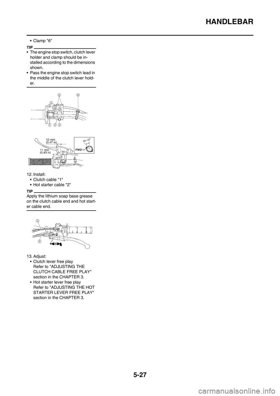
• Clamp "6"
• The engine stop switch, clutch lever
holder and clamp should be in-
stalled according to the dimensions
shown.
• Pass the engine stop switch lead in
the middle of the clutch lever hold-
er.
12. Install:
• Clutch cable "1"
• Hot starter cable "2"
Apply the lithium soap base grease
on the clutch cable end and hot start-
er cable end.
13. Adjust:
• Clutch lever free play
Refer to "ADJUSTING THE
CLUTCH CABLE FREE PLAY"
section in the CHAPTER 3.
• Hot starter lever free play
Refer to "ADJUSTING THE HOT
STARTER LEVER FREE PLAY"
section in the CHAPTER 3.
Page 167 of 198
5-28
STEERING
STEERING
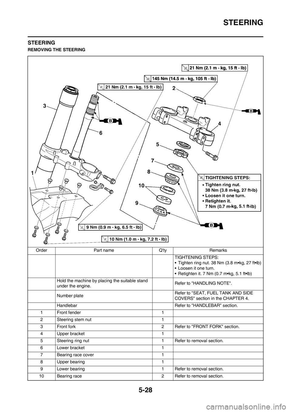
REMOVING THE STEERING
Order Part name Q'ty Remarks
TIGHTENING STEPS:
• Tighten ring nut. 38 Nm (3.8 m•kg, 27 ft•lb)
• Loosen it one turn.
• Retighten it. 7 Nm (0.7 m•kg, 5.1 ft•lb)
Hold the machine by placing the suitable stand
under the engine.Refer to "HANDLING NOTE".
Number plateRefer to "SEAT, FUEL TANK AND SIDE
COVERS" section in the CHAPTER 4.
Handlebar Refer to "HANDLEBAR" section.
1 Front fender 1
2 Steering stem nut 1
3 Front fork 2 Refer to "FRONT FORK" section.
4 Upper bracket 1
5 Steering ring nut 1 Refer to removal section.
6 Lower bracket 1
7 Bearing race cover 1
8 Upper bearing 1
9 Lower bearing 1 Refer to removal section.
10 Bearing race 2 Refer to removal section.
Page 170 of 198
5-31
SWINGARM
SWINGARM
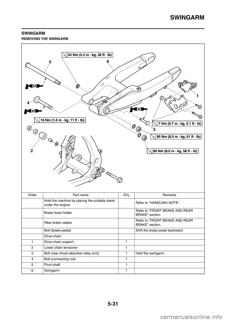
REMOVING THE SWINGARM
Order Part name Q'ty Remarks
Hold the machine by placing the suitable stand
under the engine.Refer to "HANDLING NOTE".
Brake hose holder Refer to "FRONT BRAKE AND REAR
BRAKE" section.
Rear brake caliperRefer to "FRONT BRAKE AND REAR
BRAKE" section.
Bolt (brake pedal) Shift the brake pedal backward.
Drive chain
1 Drive chain support 1
2 Lower chain tensioner 1
3 Bolt (rear shock absorber-relay arm) 1 Hold the swingarm.
4 Bolt (connecting rod) 1
5 Pivot shaft 1
6 Swingarm 1
Page 175 of 198
5-36
REAR SHOCK ABSORBER
REAR SHOCK ABSORBER
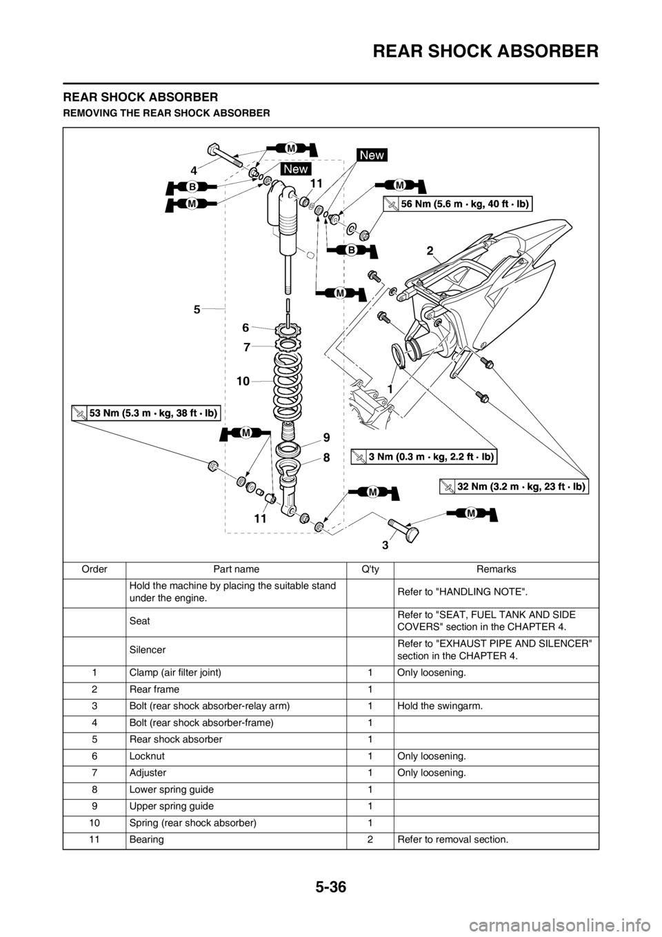
REMOVING THE REAR SHOCK ABSORBER
Order Part name Q'ty Remarks
Hold the machine by placing the suitable stand
under the engine.Refer to "HANDLING NOTE".
Seat Refer to "SEAT, FUEL TANK AND SIDE
COVERS" section in the CHAPTER 4.
Silencer Refer to "EXHAUST PIPE AND SILENCER"
section in the CHAPTER 4.
1 Clamp (air filter joint) 1 Only loosening.
2Rear frame 1
3 Bolt (rear shock absorber-relay arm) 1 Hold the swingarm.
4 Bolt (rear shock absorber-frame) 1
5 Rear shock absorber 1
6 Locknut 1 Only loosening.
7 Adjuster 1 Only loosening.
8 Lower spring guide 1
9 Upper spring guide 1
10 Spring (rear shock absorber) 1
11 Bearing 2 Refer to removal section.
B2
9
8 10
11
11
Page 179 of 198
6-1
ELECTRICAL
This section is intended for those who have basic knowledge and skill concerning the servicing of Yamaha motorcycles
(e.g., Yamaha dealers, service engineers, etc.) Those who have little knowledge and skill concerning servicing are request-
ed not to undertake inspection, adjustment, disassembly, or reassembly only by reference to this manual. It may lead to
servicing trouble and mechanical damage.
6
Page 180 of 198
6-2
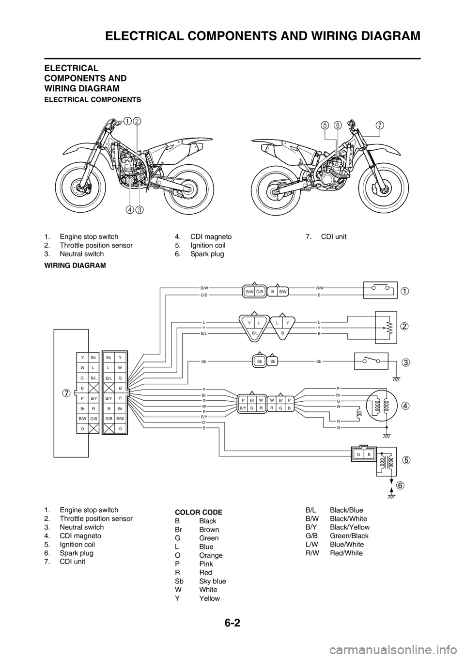
ELECTRICAL COMPONENTS AND WIRING DIAGRAM
ELECTRICAL
COMPONENTS AND
WIRING DIAGRAM
ELECTRICAL COMPONENTS
1. Engine stop switch
2. Throttle position sensor
3. Neutral switch4. CDI magneto
5. Ignition coil
6. Spark plug7. CDI unit
WIRING DIAGRAM
1. Engine stop switch
2. Throttle position sensor
3. Neutral switch
4. CDI magneto
5. Ignition coil
6. Spark plug
7. CDI unit COLOR CODE
BBlack
Br Brown
GGreen
LBlue
O Orange
PPink
RRed
Sb Sky blue
WWhite
YYellowB/L Black/Blue
B/W Black/White
B/Y Black/Yellow
G/B Green/Black
L/W Blue/White
R/W Red/White
B/WB/W
B/L
B/Y
SbSb
G/B
LYLY
P
B
B
B
B
G
O
WR
P
GW
R
P
B
Br W
W
B/Y G Br
G
RR
OB
Sb Sb
Y
Y
W Y
W
GG B
P P
Br BrRR
O L
B
Sb Y
LL
B/L
B/W
B/W
G/B
B
B
B/L
L
Sb
B/L
G/B
G/B B/Y
B/Y
B/W O
B/W
BrBrP
Page 181 of 198
6-3
IGNITION SYSTEM
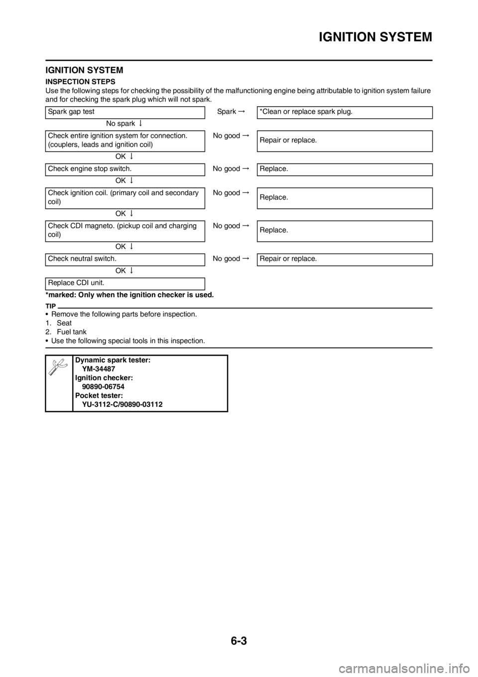
IGNITION SYSTEM
INSPECTION STEPS
Use the following steps for checking the possibility of the malfunctioning engine being attributable to ignition system failure
and for checking the spark plug which will not spark.
*marked: Only when the ignition checker is used.
• Remove the following parts before inspection.
1. Seat
2. Fuel tank
• Use the following special tools in this inspection.
Spark gap test Spark→*Clean or replace spark plug.
No spark↓
Check entire ignition system for connection.
(couplers, leads and ignition coil)No good→
Repair or replace.
OK↓
Check engine stop switch. No good→Replace.
OK↓
Check ignition coil. (primary coil and secondary
coil)No good→
Replace.
OK↓
Check CDI magneto. (pickup coil and charging
coil)No good→
Replace.
OK↓
Check neutral switch. No good→Repair or replace.
OK↓
Replace CDI unit.
Dynamic spark tester:
YM-34487
Ignition checker:
90890-06754
Pocket tester:
YU-3112-C/90890-03112
Page 182 of 198
6-4
IGNITION SYSTEM
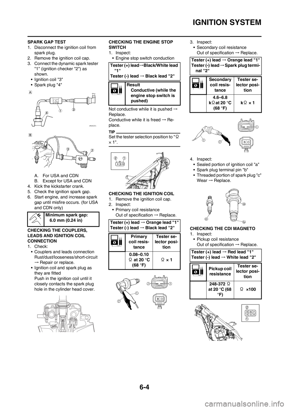
SPARK GAP TEST
1. Disconnect the ignition coil from
spark plug.
2. Remove the ignition coil cap.
3. Connect the dynamic spark tester
"1" (ignition checker "2") as
shown.
• Ignition coil "3"
• Spark plug "4"
A. For USA and CDN
B. Except for USA and CDN
4. Kick the kickstarter crank.
5. Check the ignition spark gap.
6. Start engine, and increase spark
gap until misfire occurs. (for USA
and CDN only)
CHECKING THE COUPLERS,
LEADS AND IGNITION COIL
CONNECTION
1. Check:
• Couplers and leads connection
Rust/dust/looseness/short-circuit
→Repair or replace.
• Ignition coil and spark plug as
they are fitted
Push in the ignition coil until it
closely contacts the spark plug
hole in the cylinder head cover.CHECKING THE ENGINE STOP
SWITCH
1. Inspect:
• Engine stop switch conduction
Not conductive while it is pushed→
Replace.
Conductive while it is freed→Re-
place.
Set the tester selection position to "Ω
× 1".
CHECKING THE IGNITION COIL
1. Remove the ignition coil cap.
2. Inspect:
• Primary coil resistance
Out of specification→Replace.3. Inspect:
• Secondary coil resistance
Out of specification→Replace.
4. Inspect:
• Sealed portion of ignition coil "a"
• Spark plug terminal pin "b"
• Threaded portion of spark plug "c"
Wear →Replace.
CHECKING THE CDI MAGNETO
1. Inspect:
• Pickup coil resistance
Out of specification→Replace. Minimum spark gap:
6.0 mm (0.24 in)
Tester (+) lead→Black/White lead
"1"
Tester (-) lead→Black lead "2"
Result
Conductive (while the
engine stop switch is
pushed)
Tester (+) lead→Orange lead "1"
Tester (-) lead→Black lead "2"
Primary
coil resis-
tanceTester se-
lector posi-
tion
0.08–0.10
Ω at 20 °C
(68 °F) Ω × 1
/W BB
Tester (+) lead→Orange lead "1"
Tester (-) lead→Spark plug termi-
nal "2"
Secondary
coil resis-
tanceTester se-
lector posi-
tion
4.6–6.8
kΩat 20 °C
(68 °F) kΩ × 1
Tester (+) lead→Red lead "1"
Tester (-) lead→White lead "2"
Pickup coil
resistanceTester se-
lector posi-
tion
248-372 Ω
at 20 °C (68
°F)Ω ×100
B WBr
GP
R
Page 185 of 198
6-7
THROTTLE POSITION SENSOR SYSTEM
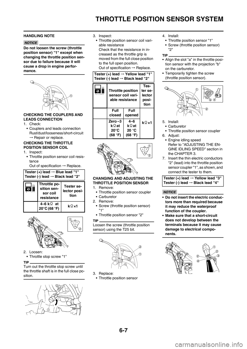
HANDLING NOTE
Do not loosen the screw (throttle
position sensor) "1" except when
changing the throttle position sen-
sor due to failure because it will
cause a drop in engine perfor-
mance.
CHECKING THE COUPLERS AND
LEADS CONNECTION
1. Check:
• Couplers and leads connection
Rust/dust/looseness/short-circuit
→Repair or replace.
CHECKING THE THROTTLE
POSITION SENSOR COIL
1. Inspect:
• Throttle position sensor coil resis-
tance
Out of specification→Replace.
2. Loosen:
• Throttle stop screw "1"
Turn out the throttle stop screw until
the throttle shaft is in the full close po-
sition.
3. Inspect:
• Throttle position sensor coil vari-
able resistance
Check that the resistance in in-
creased as the throttle grip is
moved from the full close position
to the full open position.
Out of specification→Replace.
CHANGING AND ADJUSTING THE
THROTTLE POSITION SENSOR
1. Remove:
• Throttle position sensor coupler
• Carburetor
2. Remove:
• Screw (throttle position sensor)
"1"
• Throttle position sensor "2"
Loosen the screw (throttle position
sensor) using the T25 bit.
3. Replace:
• Throttle position sensor4. Install:
• Throttle position sensor "1"
• Screw (throttle position sensor)
"2"
• Align the slot "a" in the throttle posi-
tion sensor with the projection "b"
on the carburetor.
• Temporarily tighten the screw
(throttle position sensor).
5. Install:
•Carburetor
• Throttle position sensor coupler
6. Adjust:
• Engine idling speed
Refer to "ADJUSTING THE EN-
GINE IDLING SPEED" section in
the CHAPTER 3.
7. Insert the thin electric conductors
"2" (lead) into the throttle position
sensor coupler "1", as shown, and
connect the tester to them.
• Do not insert the electric conduc-
tors more than required because
it may reduce the waterproof
function of the coupler.
• Make sure that a short-circuit
does not develop between the
terminals because it may cause
damage to electrical compo-
nents.
Tester (+) lead→Blue lead "1"
Tester (-) lead→Black lead "2"
Throttle po-
sition sen-
sor coil
resistanceTester se-
lector posi-
tion
4–6 kΩ at
20°C (68 °F) kΩ×1
Y
B L
Tester (+) lead→Yellow lead "1"
Tester (-) lead→Black lead "2"
Throttle position
sensor coil vari-
able resistanceTes-
ter se-
lector
posi-
tion
Full
closedFull
opened
kΩ×1 Zero –3
kΩat
20°C
(68 °F)4–6
kΩat
20 °C
(68 °F)
Y
B L
Tester (+) lead→Yellow lead "3"
Tester (-) lead→Black lead "4"
Page 186 of 198
6-8
THROTTLE POSITION SENSOR SYSTEM
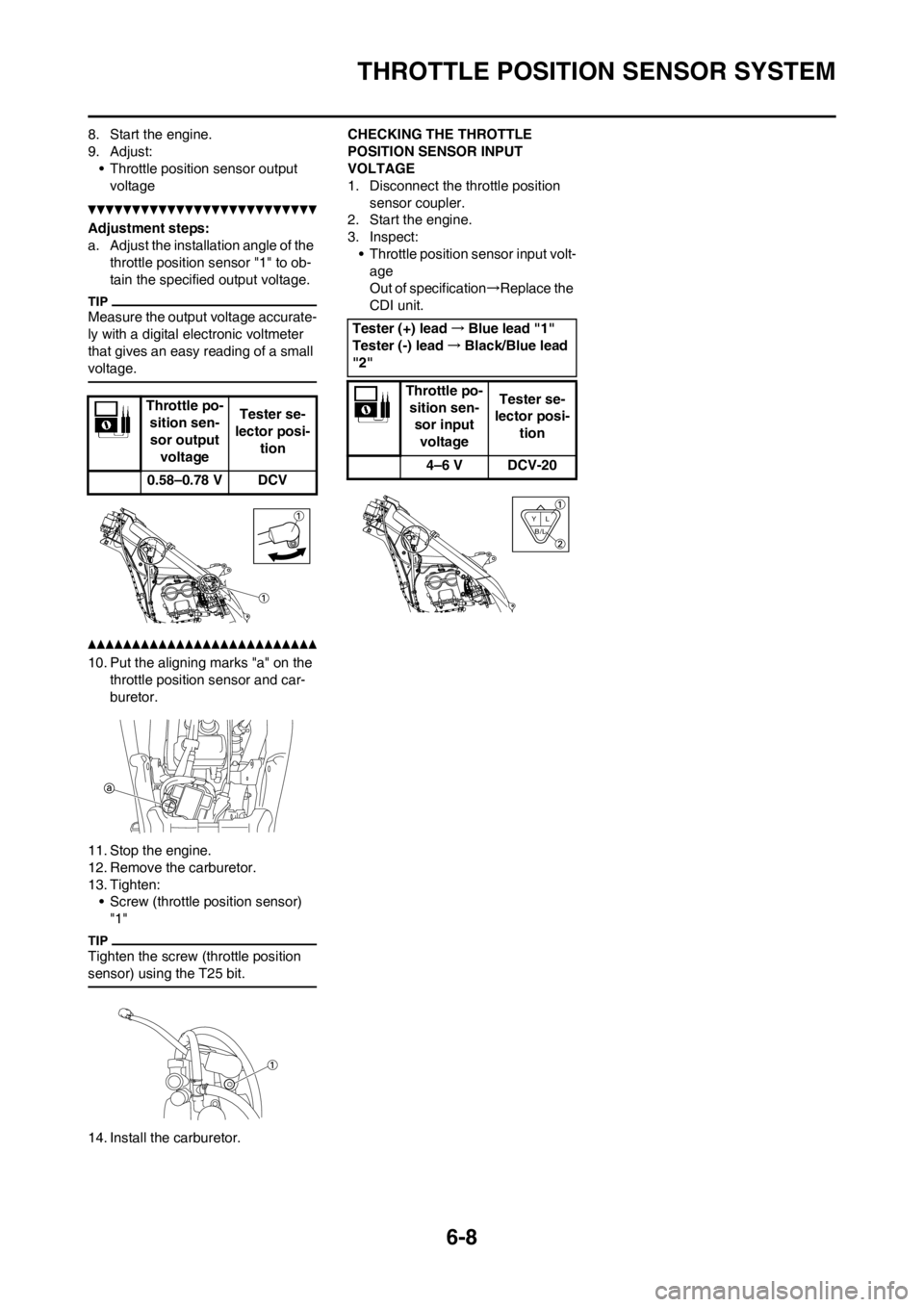
8. Start the engine.
9. Adjust:
• Throttle position sensor output
voltage
Adjustment steps:
a. Adjust the installation angle of the
throttle position sensor "1" to ob-
tain the specified output voltage.
Measure the output voltage accurate-
ly with a digital electronic voltmeter
that gives an easy reading of a small
voltage.
10. Put the aligning marks "a" on the
throttle position sensor and car-
buretor.
11. Stop the engine.
12. Remove the carburetor.
13. Tighten:
• Screw (throttle position sensor)
"1"
Tighten the screw (throttle position
sensor) using the T25 bit.
14. Install the carburetor.CHECKING THE THROTTLE
POSITION SENSOR INPUT
VOLTAGE
1. Disconnect the throttle position
sensor coupler.
2. Start the engine.
3. Inspect:
• Throttle position sensor input volt-
age
Out of specification→Replace the
CDI unit.
Throttle po-
sition sen-
sor output
voltageTester se-
lector posi-
tion
0.58–0.78 V DCV
Tester (+) lead→Blue lead "1"
Tester (-) lead→Black/Blue lead
"2"
Throttle po-
sition sen-
sor input
voltage Tester se-
lector posi-
tion
4–6 V DCV-20
L Y
B/L