clutch YAMAHA YZ250F 2015 User Guide
[x] Cancel search | Manufacturer: YAMAHA, Model Year: 2015, Model line: YZ250F, Model: YAMAHA YZ250F 2015Pages: 356, PDF Size: 11.39 MB
Page 79 of 356

CABLE ROUTING DIAGRAM
2-36
1. Throttle cable
2. Clutch cable
3. Engine stop switch lead
4. Cable guide
5. Head pipe
6. Front brake hose
7. Brake hose guide
8. Number plate
A. Number plate band
B. Pass the clutch cable to the rear of the number
plate band.
C. Clamp the engine stop switch lead to the handle-
bar by the plastic band. Do not cut the end of the
plastic band.
D. Pass the engine stop switch lead between the
head pipe and the cable guide.
E. Pass the front brake hose to the front of the num-
ber plate.
F. 40°±10°
G. Vertical direction
H. Pass the engine stop switch lead under the han-
dlebar.
I. Pass the clutch cable to the guide in the number
plate.
Page 85 of 356

3
PERIODIC CHECKS AND ADJUSTMENTS
MAINTENANCE INTERVALS.......................................................................... 3-1
MAINTENANCE INTERVALS .................................................................... 3-1
PRE-OPERATION INSPECTION AND MAINTENANCE................................. 3-7
GENERAL INSPECTION AND MAINTENANCE........................................ 3-7
ENGINE............................................................................................................ 3-8
CHECKING THE COOLANT LEVEL .......................................................... 3-8
CHECKING THE COOLING SYSTEM ....................................................... 3-8
CHANGING THE COOLANT...................................................................... 3-8
CHECKING THE RADIATOR CAP ............................................................ 3-9
CHECKING THE RADIATOR CAP OPENING PRESSURE ...................... 3-9
CHECKING THE COOLANT CIRCULATORY SYSTEM FOR LEAKS .... 3-10
ADJUSTING THE CLUTCH LEVER POSITION ...................................... 3-10
ADJUSTING THE CLUTCH LEVER FREE PLAY .................................... 3-10
ADJUSTING THE THROTTLE GRIP FREE PLAY .................................. 3-11
LUBRICATING THE THROTTLE CABLE ................................................ 3-12
CLEANING THE AIR FILTER ELEMENT................................................. 3-12
CHECKING THE THROTTLE BODY JOINT ............................................ 3-13
CHECKING THE BREATHER HOSES .................................................... 3-13
CHECKING THE EXHAUST SYSTEM..................................................... 3-13
CHECKING THE FUEL LINE ................................................................... 3-14
CHECKING THE ENGINE OIL LEVEL..................................................... 3-14
CHANGING THE ENGINE OIL ................................................................ 3-15
ADJUSTING THE ENGINE IDLING SPEED ............................................ 3-16
ADJUSTING THE VALVE CLEARANCE ................................................. 3-17
CHASSIS........................................................................................................ 3-21
BLEEDING THE BRAKE SYSTEM .......................................................... 3-21
CHECKING THE BRAKE HOSE .............................................................. 3-22
ADJUSTING THE FRONT BRAKE .......................................................... 3-22
ADJUSTING THE REAR BRAKE ............................................................. 3-23
CHECKING THE FRONT BRAKE PADS ................................................. 3-23
CHECKING THE REAR BRAKE PADS ................................................... 3-25
CHECKING THE REAR BRAKE PAD INSULATOR ................................ 3-26
CHECKING THE BRAKE FLUID LEVEL.................................................. 3-26
ADJUSTING THE DRIVE CHAIN SLACK ................................................ 3-27
CHECKING THE FRONT FORK LEGS ................................................... 3-28
CHECKING THE FRONT FORK PROTECTOR GUIDE .......................... 3-28
CLEANING THE FRONT FORK OIL SEAL AND DUST SEAL ................ 3-28
AIR BLEEDING FROM FRONT FORK .................................................... 3-28
ADJUSTING THE FRONT FORK LEGS .................................................. 3-29
CHECKING THE SWINGARM OPERATION ........................................... 3-30
CHECKING THE REAR SUSPENSION ................................................... 3-30
ADJUSTING THE REAR SHOCK ABSORBER ASSEMBLY ................... 3-30
CHECKING THE TIRES ........................................................................... 3-32
CHECKING AND TIGHTENING THE SPOKES ....................................... 3-32
CHECKING THE WHEELS ...................................................................... 3-33
Page 88 of 356
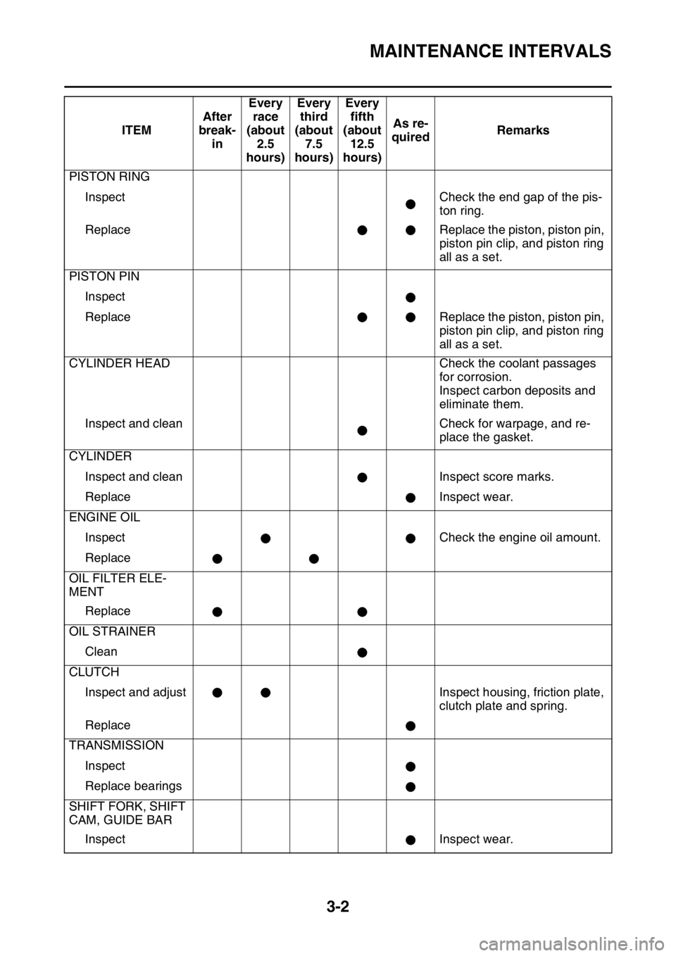
MAINTENANCE INTERVALS
3-2
PISTON RING
Inspect Check the end gap of the pis-
ton ring.
Replace Replace the piston, piston pin,
piston pin clip, and piston ring
all as a set.
PISTON PIN
Inspect
Replace Replace the piston, piston pin,
piston pin clip, and piston ring
all as a set.
CYLINDER HEAD Check the coolant passages
for corrosion.
Inspect carbon deposits and
eliminate them.
Inspect and clean Check for warpage, and re-
place the gasket.
CYLINDER
Inspect and clean Inspect score marks.
Replace Inspect wear.
ENGINE OIL
Inspect Check the engine oil amount.
Replace
OIL FILTER ELE-
MENT
Replace
OIL STRAINER
Clean
CLUTCH
Inspect and adjust Inspect housing, friction plate,
clutch plate and spring.
Replace
TRANSMISSION
Inspect
Replace bearings
SHIFT FORK, SHIFT
CAM, GUIDE BAR
Inspect Inspect wear.ITEMAfter
break-
inEvery
race
(about
2.5
hours)Every
third
(about
7.5
hours)Every
fifth
(about
12.5
hours)As re-
quiredRemarks
Page 92 of 356

MAINTENANCE INTERVALS
3-6
LEVERS
Adjust clutch lever
free play
KICKSTARTER LE-
VER, BRAKE PED-
AL, FOOTREST
Lubricate
OUTSIDE NUTS
AND BOLTS
Retighten Refer to “TORQUE-CHECK
POINTS” on page 1-25. ITEMAfter
break-
inEvery
race
(about
2.5
hours)Every
third
(about
7.5
hours)Every
fifth
(about
12.5
hours)As re-
quiredRemarks
Page 93 of 356

PRE-OPERATION INSPECTION AND MAINTENANCE
3-7
EAS1SM5068
PRE-OPERATION INSPECTION AND MAINTENANCE
Before riding for break-in operation, practice or a race, make sure the machine is in good operating
condition.
Before using this machine, check the following points.
EAS1SM5069GENERAL INSPECTION AND MAINTENANCE
TIP
Perform usual maintenance enough so that, in the race course, a confirmation of that and simple set-
ting adjustments may only be left, in order to get enough time to use effectively.ITEM inspect Page
CoolantCheck that coolant is filled up to the radiator cap.
Check the cooling system for leakage.3-8 – 10
FuelCheck that a fresh gasoline is filled in the fuel tank.
Check the fuel line for leakage.1-22
Engine oilCheck that the oil level is correct. Check the crank-
case and oil line for leakage.3-14 – 16
Gear shifter and clutchCheck that gears can be shifted correctly in order and
that the clutch operates smoothly.3-10 – 11
Throttle grip/HousingCheck that the throttle grip operation and free play
are correctly adjusted. Lubricate the throttle grip and
housing, if necessary.3-11 – 12
BrakesCheck the play of front brake and effect of front and
rear brake.3-21 – 27
Drive chainCheck drive chain slack and alignment. Check that
the drive chain is lubricated properly.3-27
4-64 – 65
WheelsCheck for excessive wear and tire pressure. Check
for loose spokes and have no excessive play.3-32 – 33
SteeringCheck that the handlebar can be turned smoothly and
have no excessive play.3-33 – 34
Front forks and rear
shock absorberCheck that they operate smoothly and there is no oil
leakage.3-28 – 32
Cables (wires)Check that the clutch and throttle cables move
smoothly. Check that they are not caught when the
handlebars are turned or when the front forks travel
up and down.—
Exhaust pipeCheck that the exhaust pipe is tightly mounted and
has no cracks.3-13 – 14
Rear wheel sprocketCheck that the rear wheel sprocket tightening bolt is
not loose.4-8 – 9
Lubrication Check for smooth operation. Lubricate if necessary. 3-12, 3-34
Bolts and nutsCheck the chassis and engine for loose bolts and
nuts.1-25 – 26
Lead connectorsCheck that the AC magneto, ECU and ignition coil are
connected tightly.1-12 – 14
SettingsIs the machine set suitably for the condition of the rac-
ing course and weather or by taking into account the
results of test runs before racing? Are inspection and
maintenance completely done?10-1 – 8
Page 96 of 356
ENGINE
3-10
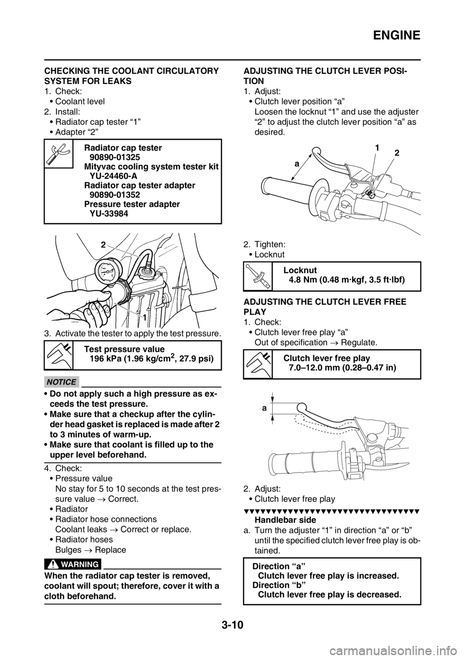
EAS1SM5076CHECKING THE COOLANT CIRCULATORY
SYSTEM FOR LEAKS
1. Check:
• Coolant level
2. Install:
• Radiator cap tester “1”
• Adapter “2”
3. Activate the tester to apply the test pressure.
ECA@
NOTICE
• Do not apply such a high pressure as ex-
ceeds the test pressure.
• Make sure that a checkup after the cylin-
der head gasket is replaced is made after 2
to 3 minutes of warm-up.
• Make sure that coolant is filled up to the
upper level beforehand.
4. Check:
• Pressure value
No stay for 5 to 10 seconds at the test pres-
sure value Correct.
• Radiator
• Radiator hose connections
Coolant leaks Correct or replace.
• Radiator hoses
Bulges Replace
EWA@
WARNING
When the radiator cap tester is removed,
coolant will spout; therefore, cover it with a
cloth beforehand.
EAS1SM5077ADJUSTING THE CLUTCH LEVER POSI-
TION
1. Adjust:
• Clutch lever position “a”
Loosen the locknut “1” and use the adjuster
“2” to adjust the clutch lever position “a” as
desired.
2. Tighten:
• Locknut
EAS1SM5078ADJUSTING THE CLUTCH LEVER FREE
PLAY
1. Check:
• Clutch lever free play “a”
Out of specification Regulate.
2. Adjust:
• Clutch lever free play
▼▼▼▼▼▼▼▼▼▼▼▼▼▼▼▼▼▼▼▼▼▼▼▼▼▼▼▼▼▼▼▼
Handlebar side
a. Turn the adjuster “1” in direction “a” or “b”
until the specified clutch lever free play is ob-
tained. Radiator cap tester
90890-01325
Mityvac cooling system tester kit
YU-24460-A
Radiator cap tester adapter
90890-01352
Pressure tester adapter
YU-33984
Test pressure value
196 kPa (1.96 kg/cm
2, 27.9 psi)
Locknut
4.8 Nm (0.48 m·kgf, 3.5 ft·lbf)
Clutch lever free play
7.0–12.0 mm (0.28–0.47 in)
Direction “a”
Clutch lever free play is increased.
Direction “b”
Clutch lever free play is decreased.
1
2
a
T R..
Page 97 of 356
ENGINE
3-11
TIP
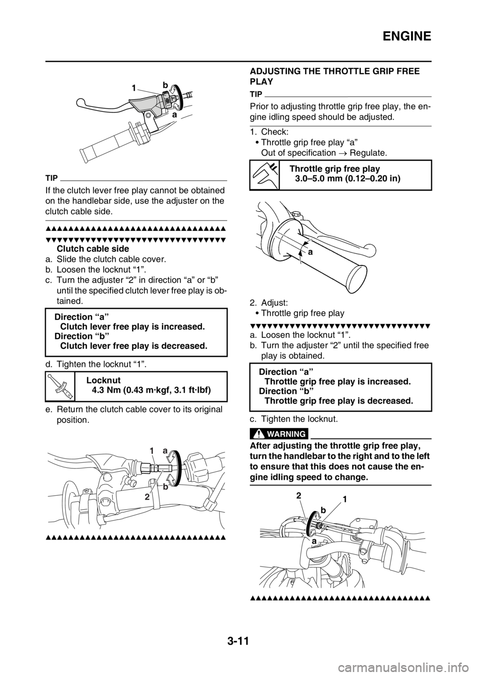
If the clutch lever free play cannot be obtained
on the handlebar side, use the adjuster on the
clutch cable side.
▲▲▲▲▲▲▲▲▲▲▲▲▲▲▲▲▲▲▲▲▲▲▲▲▲▲▲▲▲▲▲▲
▼▼▼▼▼▼▼▼▼▼▼▼▼▼▼▼▼▼▼▼▼▼▼▼▼▼▼▼▼▼▼▼
Clutch cable side
a. Slide the clutch cable cover.
b. Loosen the locknut “1”.
c. Turn the adjuster “2” in direction “a” or “b”
until the specified clutch lever free play is ob-
tained.
d. Tighten the locknut “1”.
e. Return the clutch cable cover to its original
position.
▲▲▲▲▲▲▲▲▲▲▲▲▲▲▲▲▲▲▲▲▲▲▲▲▲▲▲▲▲▲▲▲
EAS1SM5079
ADJUSTING THE THROTTLE GRIP FREE
PLAY
TIP
Prior to adjusting throttle grip free play, the en-
gine idling speed should be adjusted.
1. Check:
• Throttle grip free play “a”
Out of specification Regulate.
2. Adjust:
• Throttle grip free play
▼▼▼▼▼▼▼▼▼▼▼▼▼▼▼▼▼▼▼▼▼▼▼▼▼▼▼▼▼▼▼▼
a. Loosen the locknut “1”.
b. Turn the adjuster “2” until the specified free
play is obtained.
c. Tighten the locknut.
EWA33DD008
WARNING
After adjusting the throttle grip free play,
turn the handlebar to the right and to the left
to ensure that this does not cause the en-
gine idling speed to change.
▲▲▲▲▲▲▲▲▲▲▲▲▲▲▲▲▲▲▲▲▲▲▲▲▲▲▲▲▲▲▲▲
Direction “a”
Clutch lever free play is increased.
Direction “b”
Clutch lever free play is decreased.
Locknut
4.3 Nm (0.43 m·kgf, 3.1 ft·lbf)
a b
1
T R..
1a
b
2
b
Throttle grip free play
3.0–5.0 mm (0.12–0.20 in)
Direction “a”
Throttle grip free play is increased.
Direction “b”
Throttle grip free play is decreased.
1 2
b
a
Page 100 of 356
ENGINE
3-14
4. Install:
• Exhaust pipe protector
EAS1SM5085CHECKING THE FUEL LINE
1. Remove:
• Seat
• Side cover (left/right)
• Air scoop (left/right)
Refer to “GENERAL CHASSIS” on page 4-
1.
• Fuel tank
Refer to “FUEL TANK” on page 7-1.
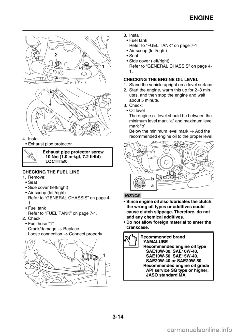
2. Check:
• Fuel hose “1”
Crack/damage Replace.
Loose connection Connect properly.3. Install:
• Fuel tank
Refer to “FUEL TANK” on page 7-1.
• Air scoop (left/right)
• Seat
• Side cover (left/right)
Refer to “GENERAL CHASSIS” on page 4-
1.
EAS1SM5086CHECKING THE ENGINE OIL LEVEL
1. Stand the vehicle upright on a level surface.
2. Start the engine, warm this up for 2–3 min-
utes, and then stop the engine and wait
about 5 minute.
3. Check:
• Oil level
The engine oil level should be between the
minimum level mark “a” and maximum level
mark “b”.
Below the minimum level mark Add the
recommended engine oil to the proper level.
ECA33DD018
NOTICE
• Since engine oil also lubricates the clutch,
the wrong oil types or additives could
cause clutch slippage. Therefore, do not
add any chemical additives.
• Do not allow foreign material to enter the
crankcase. Exhaust pipe protector screw
10 Nm (1.0 m·kgf, 7.2 ft·lbf)
LOCTITE®
2
1
4
3
T R..
1
Recommended brand
YAMALUBE
Recommended engine oil type
SAE10W-30, SAE10W-40,
SAE10W-50, SAE15W-40,
SAE20W-40 or SAE20W-50
Recommended engine oil grade
API service SG type or higher,
JASO standard MA
a b
Page 120 of 356
CHASSIS
3-34
c. Turn the front fork to the right and left a few
times, and make sure that the steering ro-
tates smoothly. If it does not turn smoothly,
remove the lower bracket and check the up-
per and lower bearings.
Refer to “STEERING HEAD” on page 4-49.
d. Loosen the ring nut fully turn and then tight-
en it to specification with a steering nut
wrench.
EWA13140
WARNING
Do not overtighten the lower ring nut.
e. Check the steering head for looseness or
binding by turning the front fork all the way in
both directions. If any binding is felt, remove
the lower bracket and check the upper and
lower bearings.
Refer to “STEERING HEAD” on page 4-49.
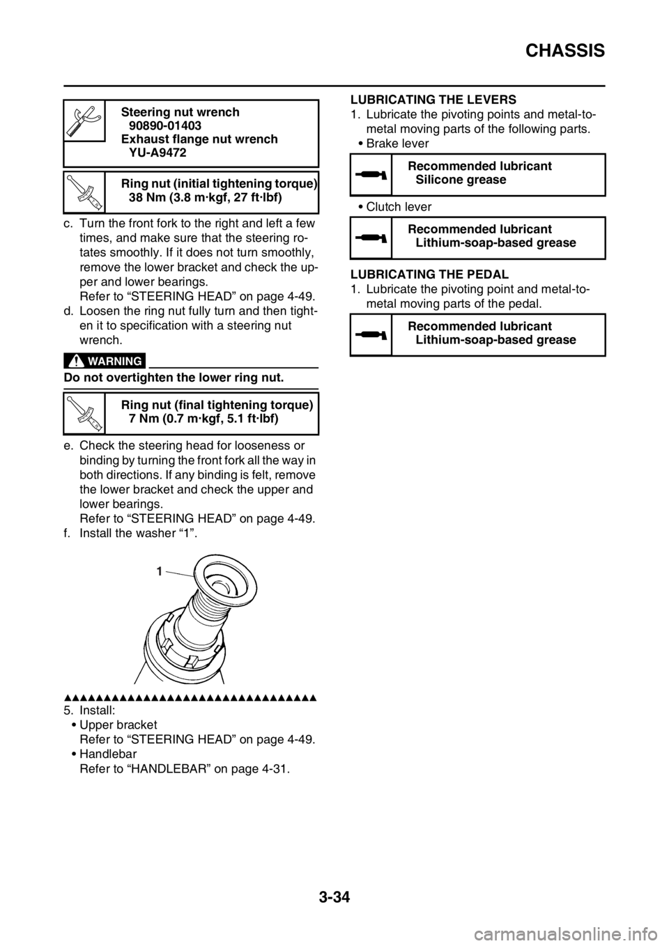
f. Install the washer “1”.
▲▲▲▲▲▲▲▲▲▲▲▲▲▲▲▲▲▲▲▲▲▲▲▲▲▲▲▲▲▲▲▲
5. Install:
• Upper bracket
Refer to “STEERING HEAD” on page 4-49.
• Handlebar
Refer to “HANDLEBAR” on page 4-31.
EAS1SM5113
LUBRICATING THE LEVERS
1. Lubricate the pivoting points and metal-to-
metal moving parts of the following parts.
•Brake lever
• Clutch lever
EAS1SM5114LUBRICATING THE PEDAL
1. Lubricate the pivoting point and metal-to-
metal moving parts of the pedal. Steering nut wrench
90890-01403
Exhaust flange nut wrench
YU-A9472
Ring nut (initial tightening torque)
38 Nm (3.8 m·kgf, 27 ft·lbf)
Ring nut (final tightening torque)
7 Nm (0.7 m·kgf, 5.1 ft·lbf)
T R..
T R..
1
Recommended lubricant
Silicone grease
Recommended lubricant
Lithium-soap-based grease
Recommended lubricant
Lithium-soap-based grease
Page 126 of 356
GENERAL CHASSIS
4-2
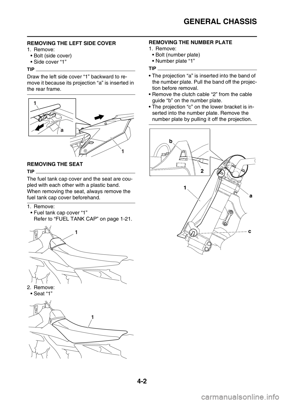
EAS1SM5120REMOVING THE LEFT SIDE COVER
1. Remove:
• Bolt (side cover)
• Side cover “1”
TIP
Draw the left side cover “1” backward to re-
move it because its projection “a” is inserted in
the rear frame.
EAS1SM5121REMOVING THE SEAT
TIP
The fuel tank cap cover and the seat are cou-
pled with each other with a plastic band.
When removing the seat, always remove the
fuel tank cap cover beforehand.
1. Remove:
• Fuel tank cap cover “1”
Refer to “FUEL TANK CAP” on page 1-21.
2. Remove:
• Seat “1”
EAS1SM5122
REMOVING THE NUMBER PLATE
1. Remove:
• Bolt (number plate)
• Number plate “1”
TIP
• The projection “a” is inserted into the band of
the number plate. Pull the band off the projec-
tion before removal.
• Remove the clutch cable “2” from the cable
guide “b” on the number plate.
• The projection “c” on the lower bracket is in-
serted into the number plate. Remove the
number plate by pulling it off the projection.
1
a
1
1
1