clutch YAMAHA YZ250F 2015 Owners Manual
[x] Cancel search | Manufacturer: YAMAHA, Model Year: 2015, Model line: YZ250F, Model: YAMAHA YZ250F 2015Pages: 356, PDF Size: 11.39 MB
Page 13 of 356

1
GENERAL INFORMATION
LOCATION OF IMPORTANT LABELS............................................................ 1-1
DESCRIPTION.................................................................................................. 1-4
IDENTIFICATION............................................................................................. 1-5
VEHICLE IDENTIFICATION NUMBER ...................................................... 1-5
ENGINE SERIAL NUMBER ....................................................................... 1-5
MODEL LABEL........................................................................................... 1-5
FEATURES....................................................................................................... 1-6
OUTLINE OF THE FI SYSTEM .................................................................. 1-6
FI SYSTEM................................................................................................. 1-7
INCLUDED PARTS.......................................................................................... 1-8
SIDESTAND ............................................................................................... 1-8
SPARK PLUG WRENCH ........................................................................... 1-8
NIPPLE WRENCH...................................................................................... 1-8
HANDLEBAR PROTECTOR ...................................................................... 1-8
FUEL HOSE JOINT COVER ...................................................................... 1-8
COUPLER FOR CONNECTING OPTIONAL PART................................... 1-8
IMPORTANT INFORMATION........................................................................ 1-10
PREPARATION FOR REMOVAL AND DISASSEMBLY.......................... 1-10
REPLACEMENT PARTS.......................................................................... 1-10
GASKETS, OIL SEALS AND O-RINGS ................................................... 1-11
LOCK WASHERS/PLATES AND COTTER PINS .................................... 1-11
BEARINGS AND OIL SEALS ................................................................... 1-11
CIRCLIPS ................................................................................................. 1-11
BASIC SERVICE INFORMATION.................................................................. 1-12
ELECTRICAL SYSTEM............................................................................ 1-12
SPECIAL TOOLS........................................................................................... 1-15
CONTROL FUNCTIONS................................................................................ 1-20
ENGINE STOP SWITCH .......................................................................... 1-20
CLUTCH LEVER...................................................................................... 1-20
SHIFT PEDAL .......................................................................................... 1-20
KICKSTARTER LEVER............................................................................ 1-20
THROTTLE GRIP ..................................................................................... 1-20
FRONT BRAKE LEVER ........................................................................... 1-20
REAR BRAKE PEDAL.............................................................................. 1-21
STARTER KNOB/IDLE ADJUSTING SCREW ......................................... 1-21
FUEL TANK CAP ..................................................................................... 1-21
Page 18 of 356
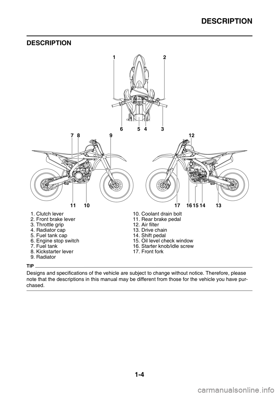
DESCRIPTION
1-4
EAS1SM5009
DESCRIPTION
TIP
Designs and specifications of the vehicle are subject to change without notice. Therefore, please
note that the descriptions in this manual may be different from those for the vehicle you have pur-
chased.1. Clutch lever 10. Coolant drain bolt
2. Front brake lever 11. Rear brake pedal
3. Throttle grip 12. Air filter
4. Radiator cap 13. Drive chain
5. Fuel tank cap 14. Shift pedal
6. Engine stop switch 15. Oil level check window
7. Fuel tank 16. Starter knob/idle screw
8. Kickstarter lever 17. Front fork
9. Radiator
2 1
6
78 954 3
11 10 17 16 15 14 1312
Page 32 of 356
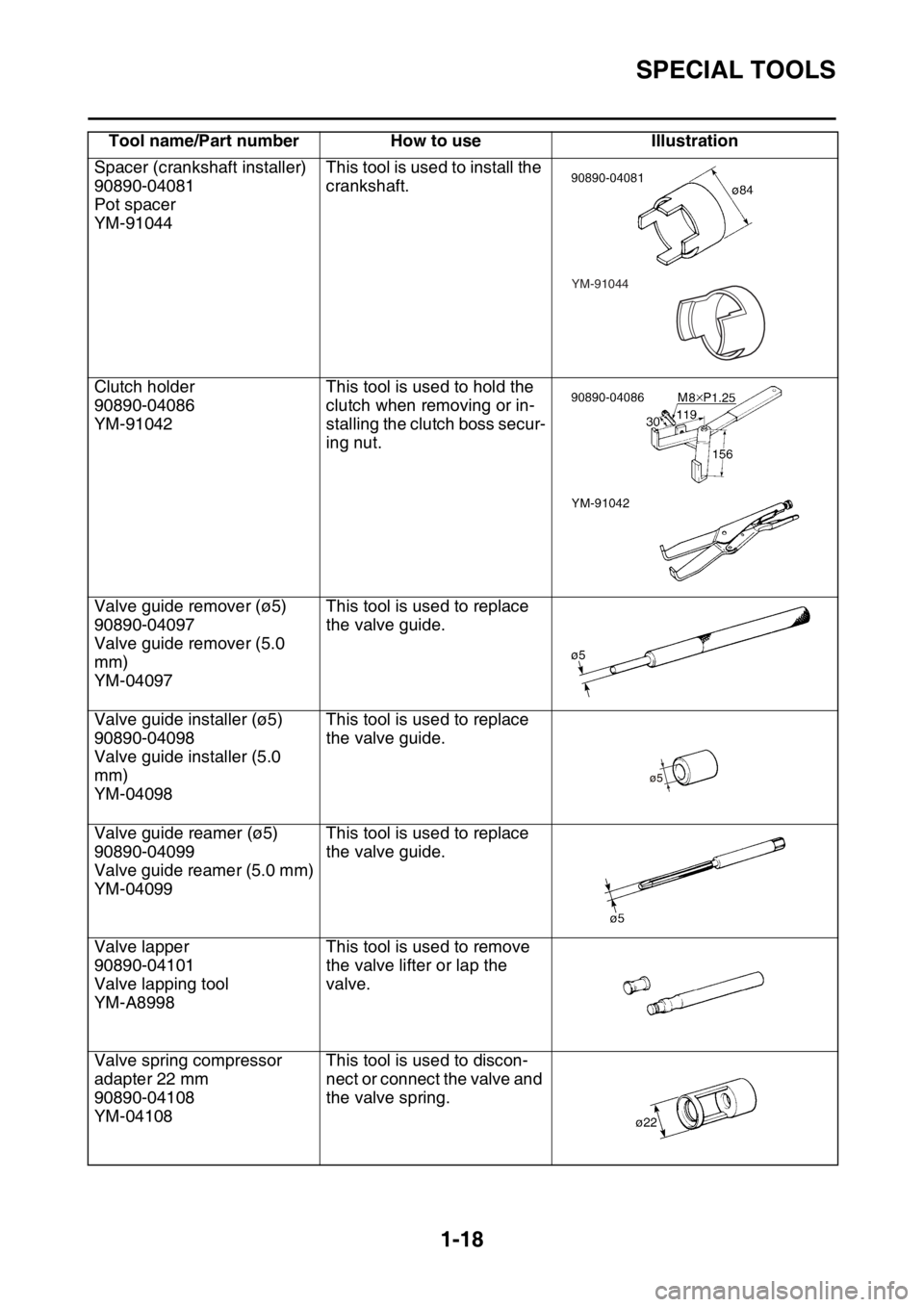
SPECIAL TOOLS
1-18
Spacer (crankshaft installer)
90890-04081
Pot spacer
YM-91044This tool is used to install the
crankshaft.
Clutch holder
90890-04086
YM-91042This tool is used to hold the
clutch when removing or in-
stalling the clutch boss secur-
ing nut.
Valve guide remover (ø5)
90890-04097
Valve guide remover (5.0
mm)
YM-04097This tool is used to replace
the valve guide.
Valve guide installer (ø5)
90890-04098
Valve guide installer (5.0
mm)
YM-04098This tool is used to replace
the valve guide.
Valve guide reamer (ø5)
90890-04099
Valve guide reamer (5.0 mm)
YM-04099This tool is used to replace
the valve guide.
Valve lapper
90890-04101
Valve lapping tool
YM-A8998This tool is used to remove
the valve lifter or lap the
valve.
Valve spring compressor
adapter 22 mm
90890-04108
YM-04108This tool is used to discon-
nect or connect the valve and
the valve spring. Tool name/Part number How to use Illustration
YM-91044
Page 34 of 356
CONTROL FUNCTIONS
1-20
EAS1SM5032
CONTROL FUNCTIONS
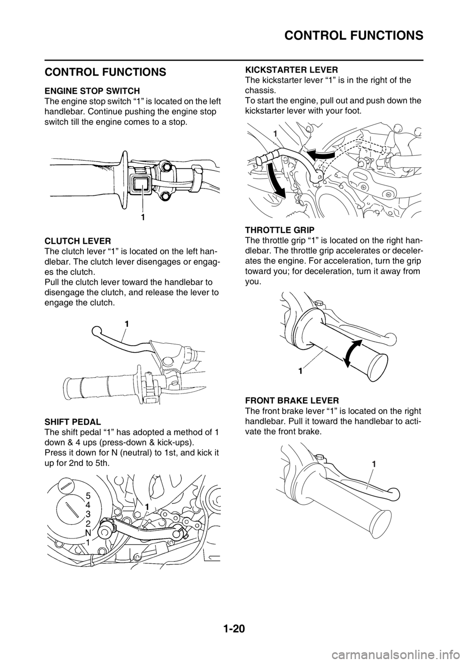
EAS1SM5033ENGINE STOP SWITCH
The engine stop switch “1” is located on the left
handlebar. Continue pushing the engine stop
switch till the engine comes to a stop.
EAS1SM5034CLUTCH LEVER
The clutch lever “1” is located on the left han-
dlebar. The clutch lever disengages or engag-
es the clutch.
Pull the clutch lever toward the handlebar to
disengage the clutch, and release the lever to
engage the clutch.
EAS1SM5035SHIFT PEDAL
The shift pedal “1” has adopted a method of 1
down & 4 ups (press-down & kick-ups).
Press it down for N (neutral) to 1st, and kick it
up for 2nd to 5th.
EAS1SM5036
KICKSTARTER LEVER
The kickstarter lever “1” is in the right of the
chassis.
To start the engine, pull out and push down the
kickstarter lever with your foot.
EAS1SM5037THROTTLE GRIP
The throttle grip “1” is located on the right han-
dlebar. The throttle grip accelerates or deceler-
ates the engine. For acceleration, turn the grip
toward you; for deceleration, turn it away from
you.
EAS1SM5038FRONT BRAKE LEVER
The front brake lever “1” is located on the right
handlebar. Pull it toward the handlebar to acti-
vate the front brake.
1
1
Page 49 of 356
ENGINE SPECIFICATIONS
2-6
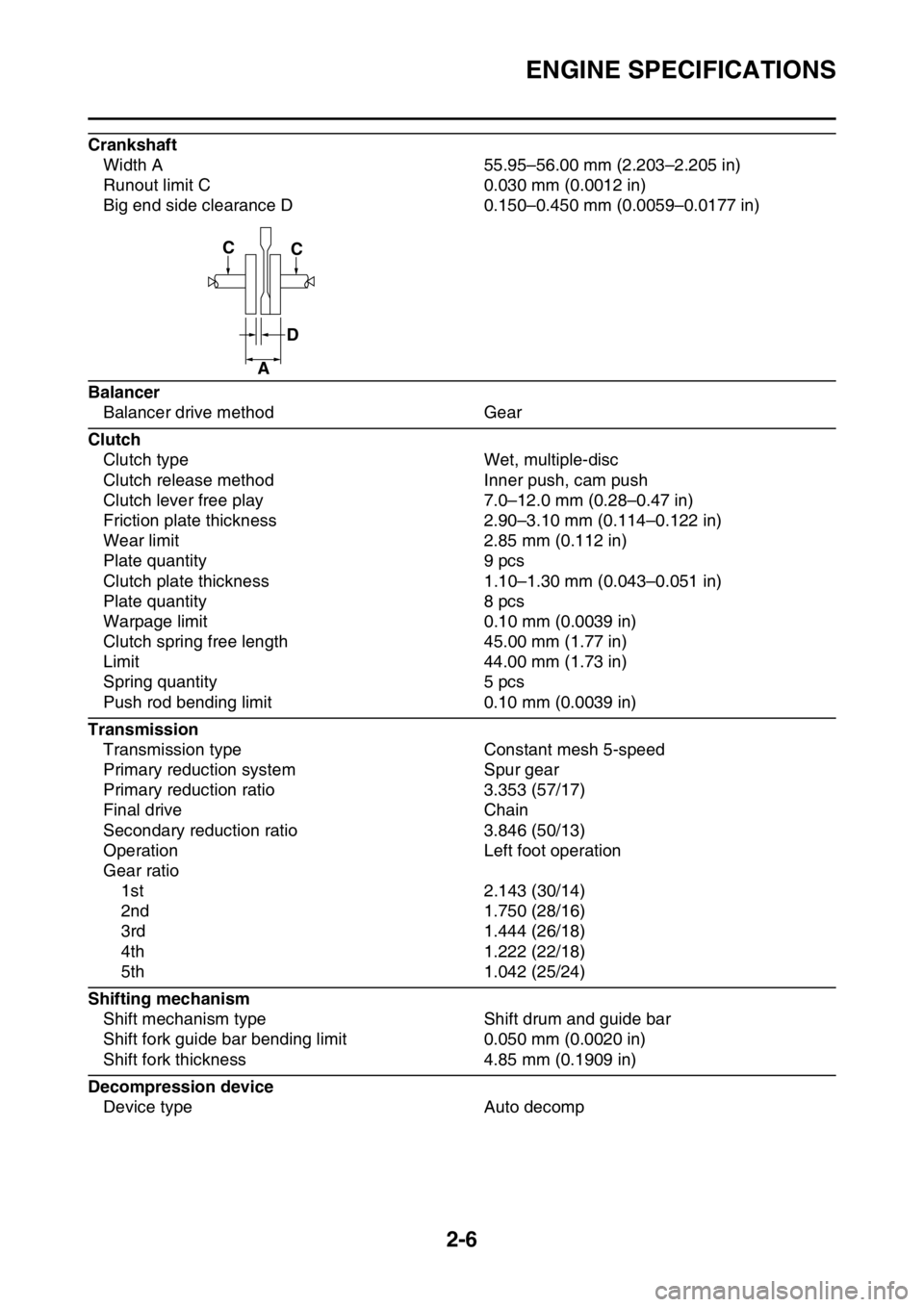
Crankshaft
Width A 55.95–56.00 mm (2.203–2.205 in)
Runout limit C 0.030 mm (0.0012 in)
Big end side clearance D 0.150–0.450 mm (0.0059–0.0177 in)
Balancer
Balancer drive method Gear
Clutch
Clutch type Wet, multiple-disc
Clutch release method Inner push, cam push
Clutch lever free play 7.0–12.0 mm (0.28–0.47 in)
Friction plate thickness 2.90–3.10 mm (0.114–0.122 in)
Wear limit 2.85 mm (0.112 in)
Plate quantity 9 pcs
Clutch plate thickness 1.10–1.30 mm (0.043–0.051 in)
Plate quantity 8 pcs
Warpage limit 0.10 mm (0.0039 in)
Clutch spring free length 45.00 mm (1.77 in)
Limit 44.00 mm (1.73 in)
Spring quantity 5 pcs
Push rod bending limit 0.10 mm (0.0039 in)
Transmission
Transmission type Constant mesh 5-speed
Primary reduction system Spur gear
Primary reduction ratio 3.353 (57/17)
Final drive Chain
Secondary reduction ratio 3.846 (50/13)
Operation Left foot operation
Gear ratio
1st 2.143 (30/14)
2nd 1.750 (28/16)
3rd 1.444 (26/18)
4th 1.222 (22/18)
5th 1.042 (25/24)
Shifting mechanism
Shift mechanism type Shift drum and guide bar
Shift fork guide bar bending limit 0.050 mm (0.0020 in)
Shift fork thickness 4.85 mm (0.1909 in)
Decompression device
Device type Auto decomp
CC
D
A
Page 57 of 356

TIGHTENING TORQUES
2-14
Air filter case cap screw
M5 1 2.5 Nm (0.25 m·kgf, 1.8 ft·lbf)
Starter knob/Idle screw
M12 1 2.1 Nm (0.21 m·kgf, 1.5 ft·lbf)
Throttle cable nut (pull)
M10 1 7 Nm (0.7 m·kgf, 5.1 ft·lbf)
Throttle cable nut (return)
M10 1 7 Nm (0.7 m·kgf, 5.1 ft·lbf)
Clutch cable adjuster and locknut
M6 1 4.3 Nm (0.43 m·kgf, 3.1 ft·lbf)
Clutch cable locknut (engine side)
M8 1 7 Nm (0.7 m·kgf, 5.1 ft·lbf)
Exhaust pipe nut
M8 2 See TIP.
Exhaust pipe protector screw
M6 4 10 Nm (1.0 m·kgf, 7.2 ft·lbf)
Exhaust pipe bracket bolt
M8 1 20 Nm (2.0 m·kgf, 14 ft·lbf)
Frame and silencer bolt (front) M8 1 30 Nm (3.0 m·kgf, 22 ft·lbf)
Frame and silencer bolt (rear) M8 1 30 Nm (3.0 m·kgf, 22 ft·lbf)
Exhaust pipe clamp bolt
M8 2 12 Nm (1.2 m·kgf, 8.7 ft·lbf)
Silencer body bolt
M5 6 8 Nm (0.8 m·kgf, 5.8 ft·lbf)
Oil nozzle bolt
M5 1 5 Nm (0.5 m·kgf, 3.6 ft·lbf)
Engine oil drain bolt
M10 1 20 Nm (2.0 m·kgf, 14 ft·lbf)
Crankcase bolt
M6 12 12 Nm (1.2 m·kgf, 8.7 ft·lbf)
Clutch cable holder bolt
M6 2 10 Nm (1.0 m·kgf, 7.2 ft·lbf)
Crankshaft end accessing screw
M36 1 10 Nm (1.0 m·kgf, 7.2 ft·lbf)
Timing mark accessing screw
M14 1 6 Nm (0.6 m·kgf, 4.3 ft·lbf)
Drive chain sprocket cover bolt
M6 2 7 Nm (0.7 m·kgf, 5.1 ft·lbf)
Crankcase bearing cover plate
screwM6 6 10 Nm (1.0 m·kgf, 7.2 ft·lbf)
Crankcase bearing cover plate
screw (crankshaft)M8 4 22 Nm (2.2 m·kgf, 16 ft·lbf)
Oil passage squeeze nozzle
M8 1 3.0 Nm (0.30 m·kgf, 2.2 ft·lbf)
Clutch cover bolt
M6 7 10 Nm (1.0 m·kgf, 7.2 ft·lbf)
Left crankcase cover bolt
M6 7 10 Nm (1.0 m·kgf, 7.2 ft·lbf)
Right crankcase cover bolt
M6 11 10 Nm (1.0 m·kgf, 7.2 ft·lbf)
Oil filter element cover bolt
M6 2 10 Nm (1.0 m·kgf, 7.2 ft·lbf)
Kick shaft ratchet wheel guide bolt
M6 2 12 Nm (1.2 m·kgf, 8.7 ft·lbf)
Kick starter lever bolt
M8 1 33 Nm (3.3 m·kgf, 24 ft·lbf)
Kick starter lever boss screw
M6 1 7 Nm (0.7 m·kgf, 5.1 ft·lbf)
Primary drive gear nut
M16 1 75 Nm (7.5 m·kgf, 54 ft·lbf)
Clutch spring bolt
M6 5 10 Nm (1.0 m·kgf, 7.2 ft·lbf)
Clutch boss nut M16 1 75 Nm (7.5 m·kgf, 54 ft·lbf)Use a
lock
washer. ITEMThread
sizeQ’ty TIGHTENING TORQUES Remarks
LT
LT
LT
LT
LT
LT
LT
LT
Page 59 of 356
TIGHTENING TORQUES
2-16
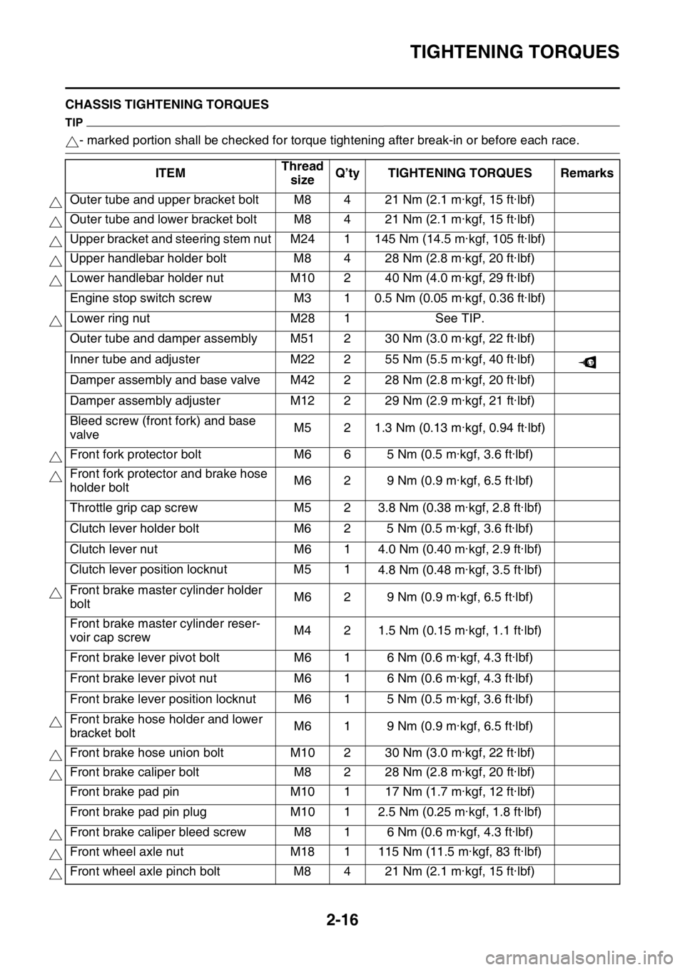
EAS1SM5059CHASSIS TIGHTENING TORQUES
TIP
- marked portion shall be checked for torque tightening after break-in or before each race.
ITEMThread
sizeQ’ty TIGHTENING TORQUES Remarks
Outer tube and upper bracket bolt M8 4 21 Nm (2.1 m·kgf, 15 ft·lbf)
Outer tube and lower bracket bolt M8 4 21 Nm (2.1 m·kgf, 15 ft·lbf)
Upper bracket and steering stem nut M24 1 145 Nm (14.5 m·kgf, 105 ft·lbf)
Upper handlebar holder bolt M8 4 28 Nm (2.8 m·kgf, 20 ft·lbf)
Lower handlebar holder nut M10 2 40 Nm (4.0 m·kgf, 29 ft·lbf)
Engine stop switch screw M3 1 0.5 Nm (0.05 m·kgf, 0.36 ft·lbf)
Lower ring nut M28 1 See TIP.
Outer tube and damper assembly M51 2 30 Nm (3.0 m·kgf, 22 ft·lbf)
Inner tube and adjuster M22 2 55 Nm (5.5 m·kgf, 40 ft·lbf)
Damper assembly and base valve M42 2 28 Nm (2.8 m·kgf, 20 ft·lbf)
Damper assembly adjuster M12 2 29 Nm (2.9 m·kgf, 21 ft·lbf)
Bleed screw (front fork) and base
valveM5 2 1.3 Nm (0.13 m·kgf, 0.94 ft·lbf)
Front fork protector bolt M6 6 5 Nm (0.5 m·kgf, 3.6 ft·lbf)
Front fork protector and brake hose
holder boltM6 2 9 Nm (0.9 m·kgf, 6.5 ft·lbf)
Throttle grip cap screw M5 2 3.8 Nm (0.38 m·kgf, 2.8 ft·lbf)
Clutch lever holder bolt M6 2 5 Nm (0.5 m·kgf, 3.6 ft·lbf)
Clutch lever nut M6 1 4.0 Nm (0.40 m·kgf, 2.9 ft·lbf)
Clutch lever position locknut M5 1
4.8 Nm (0.48 m·kgf, 3.5 ft·lbf)
Front brake master cylinder holder
boltM6 2 9 Nm (0.9 m·kgf, 6.5 ft·lbf)
Front brake master cylinder reser-
voir cap screwM4 2 1.5 Nm (0.15 m·kgf, 1.1 ft·lbf)
Front brake lever pivot bolt M6 1 6 Nm (0.6 m·kgf, 4.3 ft·lbf)
Front brake lever pivot nut M6 1 6 Nm (0.6 m·kgf, 4.3 ft·lbf)
Front brake lever position locknut M6 1 5 Nm (0.5 m·kgf, 3.6 ft·lbf)
Front brake hose holder and lower
bracket boltM6 1 9 Nm (0.9 m·kgf, 6.5 ft·lbf)
Front brake hose union bolt M10 2 30 Nm (3.0 m·kgf, 22 ft·lbf)
Front brake caliper bolt M8 2 28 Nm (2.8 m·kgf, 20 ft·lbf)
Front brake pad pin M10 1 17 Nm (1.7 m·kgf, 12 ft·lbf)
Front brake pad pin plug M10 1 2.5 Nm (0.25 m·kgf, 1.8 ft·lbf)
Front brake caliper bleed screw M8 1 6 Nm (0.6 m·kgf, 4.3 ft·lbf)
Front wheel axle nut M18 1 115 Nm (11.5 m·kgf, 83 ft·lbf)
Front wheel axle pinch bolt M8 4 21 Nm (2.1 m·kgf, 15 ft·lbf)
LT
Page 62 of 356
LUBRICATION POINTS AND LUBRICANT TYPES
2-19
EAS1SM5060
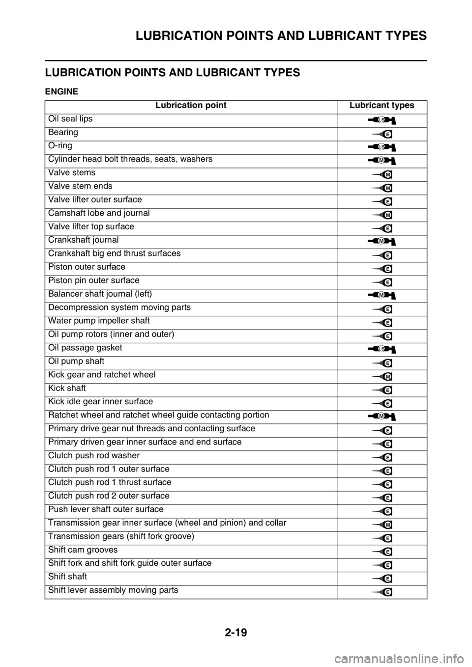
LUBRICATION POINTS AND LUBRICANT TYPES
EAS1SM5061ENGINE
Lubrication point Lubricant types
Oil seal lips
Bearing
O-ring
Cylinder head bolt threads, seats, washers
Valve stems
Valve stem ends
Valve lifter outer surface
Camshaft lobe and journal
Valve lifter top surface
Crankshaft journal
Crankshaft big end thrust surfaces
Piston outer surface
Piston pin outer surface
Balancer shaft journal (left)
Decompression system moving parts
Water pump impeller shaft
Oil pump rotors (inner and outer)
Oil passage gasket
Oil pump shaft
Kick gear and ratchet wheel
Kick shaft
Kick idle gear inner surface
Ratchet wheel and ratchet wheel guide contacting portion
Primary drive gear nut threads and contacting surface
Primary driven gear inner surface and end surface
Clutch push rod washer
Clutch push rod 1 outer surface
Clutch push rod 1 thrust surface
Clutch push rod 2 outer surface
Push lever shaft outer surface
Transmission gear inner surface (wheel and pinion) and collar
Transmission gears (shift fork groove)
Shift cam grooves
Shift fork and shift fork guide outer surface
Shift shaft
Shift lever assembly moving parts
LS
E
LS
M
M
M
E
M
E
M
E
E
E
M
E
E
E
LS
E
M
E
E
M
E
E
E
E
E
E
E
M
E
E
E
E
E
Page 64 of 356
LUBRICATION POINTS AND LUBRICANT TYPES
2-21
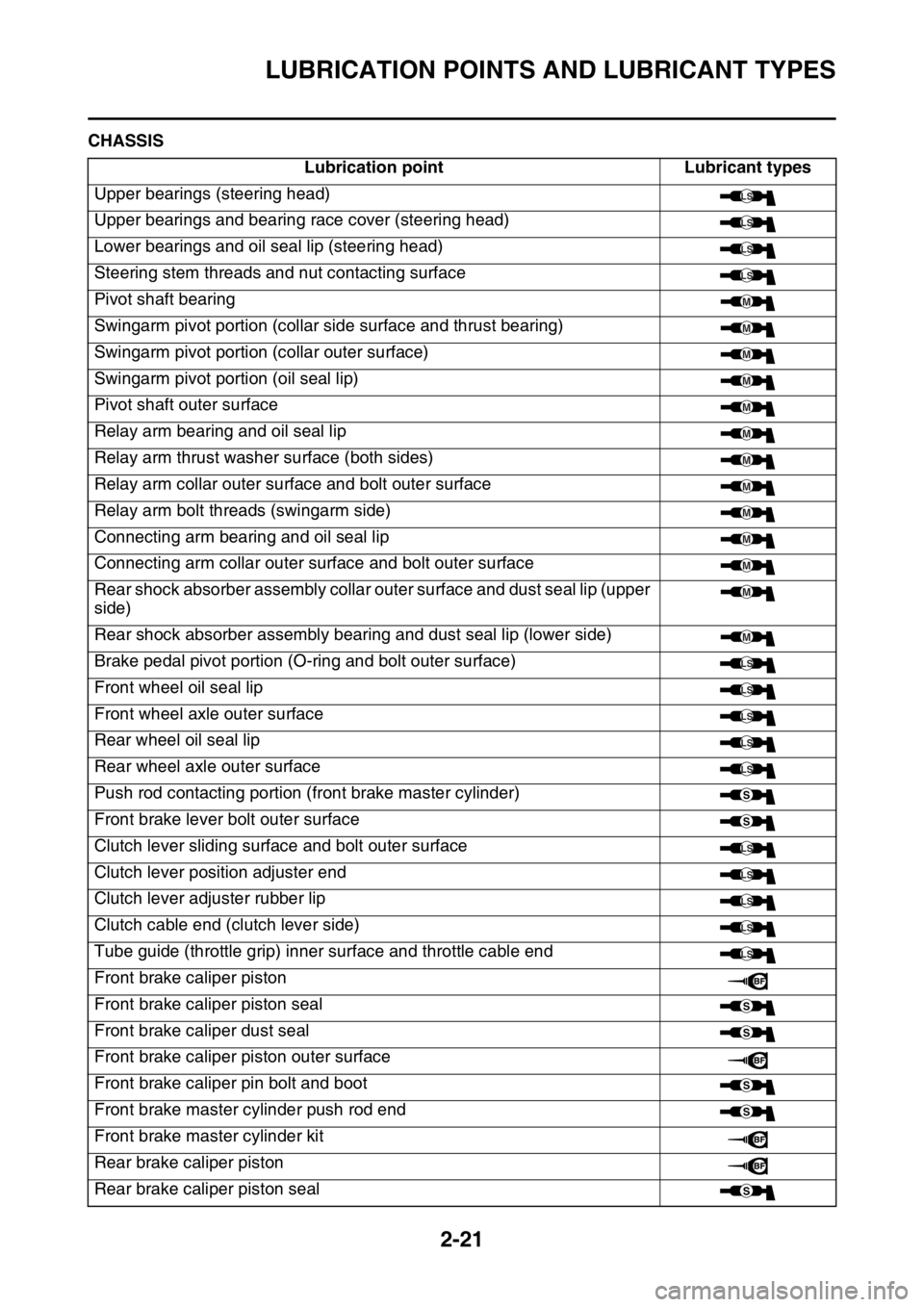
EAS1SM5062CHASSIS
Lubrication point Lubricant types
Upper bearings (steering head)
Upper bearings and bearing race cover (steering head)
Lower bearings and oil seal lip (steering head)
Steering stem threads and nut contacting surface
Pivot shaft bearing
Swingarm pivot portion (collar side surface and thrust bearing)
Swingarm pivot portion (collar outer surface)
Swingarm pivot portion (oil seal lip)
Pivot shaft outer surface
Relay arm bearing and oil seal lip
Relay arm thrust washer surface (both sides)
Relay arm collar outer surface and bolt outer surface
Relay arm bolt threads (swingarm side)
Connecting arm bearing and oil seal lip
Connecting arm collar outer surface and bolt outer surface
Rear shock absorber assembly collar outer surface and dust seal lip (upper
side)
Rear shock absorber assembly bearing and dust seal lip (lower side)
Brake pedal pivot portion (O-ring and bolt outer surface)
Front wheel oil seal lip
Front wheel axle outer surface
Rear wheel oil seal lip
Rear wheel axle outer surface
Push rod contacting portion (front brake master cylinder)
Front brake lever bolt outer surface
Clutch lever sliding surface and bolt outer surface
Clutch lever position adjuster end
Clutch lever adjuster rubber lip
Clutch cable end (clutch lever side)
Tube guide (throttle grip) inner surface and throttle cable end
Front brake caliper piston
Front brake caliper piston seal
Front brake caliper dust seal
Front brake caliper piston outer surface
Front brake caliper pin bolt and boot
Front brake master cylinder push rod end
Front brake master cylinder kit
Rear brake caliper piston
Rear brake caliper piston seal
LS
LS
LS
LS
M
M
M
M
M
M
M
M
M
M
M
M
M
LS
LS
LS
LS
LS
S
S
LS
LS
LS
LS
LS
S
S
S
S
S
Page 75 of 356

CABLE ROUTING DIAGRAM
2-32
1. Clutch cable
2. Throttle cable (pull)
3. Throttle cable (return)
4. Cable holder
5. Engine stop switch lead
6. Frame
7. Coupler for connecting optional part
8. Bracket
9. Engine stop switch coupler
10. Rectifier/regulator coupler
11. Starter knob/idle screw
12. Neutral switch lead
13. Crankcase cover
14. AC magneto lead
15. Front engine bracket
16. Radiator hose
17. Coupler cover
18. Tension arm
19. Rectifier/regulator lead
20. Main harness
21. Tank rail
22. Radiator
23. Cylinder head breather hose
24. Radiator breather hose
25. Down tube
26. Crankcase
A. Pass the engine stop switch lead between the
frame and the cable holder.
B. Pass the engine stop switch lead between the
coupler for connecting optional part and the
frame, where the main harness should face the
outside of the vehicle.
C. Insert the coupler for connecting optional part into
the connector, and fix it to the bracket.
D. Insert and fix the engine stop switch coupler to
the bracket.
E. Insert and fix the rectifier/regulator coupler to the
bracket.
F. Pass the AC magneto lead to the front of the ve-
hicle beyond the starter knob/idle screw and to
the rear of the vehicle beyond the radiator. No
pinch is allowed between the radiator and the
tension arm.
G. 70 mm (2.76 in)
H. Bring the neutral switch lead into line with the
crankcase cover with no sag allowed.
I. Bring the AC magneto lead into line with the
clutch cable with no sag allowed.
J. Pass the neutral switch lead to the inside of the
front engine bracket (the side of the vehicle).
K. Clamp the clutch cable and the AC magneto lead
by the plastic locking tie. Regardless of the orien-
tation of the lock on the plastic locking tie, cut the
end.
L. Pass the clutch cable with no downward sag al-
lowed.
M. Bring the grommet of the clutch cable into contact
with the radiator hose, and pass it to the outside
of the neutral switch lead and the AC magneto
lead (the outside of the vehicle).
N. 40 mm (1.57 in)
O. Clamp the clutch cable, the AC magneto lead,
and the neutral switch lead by the plastic locking
tie. Make sure that they are clamped at the posi-
tioning tape in the clutch cable. Make the lock on
the plastic locking tie face the front of the vehicle,
and cut the end.
P. After connecting the neutral switch coupler, at-
tach the coupler cover.
Q. After connecting the AC magneto coupler, attach
the coupler cover.R. Pass the rectifier/regulator lead to the inside of
the tension arm (the side of the vehicle).
S. Pass the main harness to the front of the radiator
hose (the front of the vehicle), and to the inside of
the clutch cable (the side of the vehicle).
T. Pass the engine stop switch lead between the
coupler for connecting optional part and the tank
rail, with the lead on the main harness side facing
the top of the vehicle.
U. Pass the radiator breather hose between the
down tubes.
V. Clamp the radiator breather hose, above the en-
gine bracket (front). Clamp the lock on the plastic
tie with it located outside the vehicle, and face the
end toward the front of the vehicle.
W. Clamp the clutch cable at the front of the lead (the
front of the vehicle).
X. Make the lock on the plastic locking tie face the
front of the vehicle, and insert the projection into
the hole in the frame. Cut the end of the plastic
locking tie.