YAMAHA YZ250LC 2001 Notices Demploi (in French)
Manufacturer: YAMAHA, Model Year: 2001, Model line: YZ250LC, Model: YAMAHA YZ250LC 2001Pages: 578, PDF Size: 14.12 MB
Page 231 of 578

ENG
4-10
CARBURATEUR ET SOUPAPE FLEXIBLE
VERGASER UND ZUNGENVENTIL
CARBURATORE E VALVOLA A LAMELLA
INSPEKTION
Vergaser
1. Prüfen:
9Vergasergehäuse
VerschmutzungÕReinigen.
ANMERKUNG:
9Lösungmittel auf Petroleumbasis für
das Reinigen verwenden. Alle
Kanäle und Düsen mit Druckluft
durchblasen.
9Niemals einen Draht verwenden.
VERIFICATION
Carburateur
1. Examiner:
9Corps du carburateur
EncrasséÕNettoyer.
N.B.:
9Pour le nettoyage, employer un dis-
solvant à base de pétrole. Passer tous
les conduits et gicleurs à l’air compri-
mé.
9Ne jamais utiliser de fil.
IC464000
ISPEZIONE
IC464130
Carburatore
1. Ispezionare:
9Corpo del carburatore
Contaminazione ÕPulirlo.
NOTA:
9Per la pulitura, usare un solvente a
base di petrolio. Soffiare con aria
compressa tutti i passaggi e i getti.
9Non usare mai un filo metallico.
Pointeau
1. Examiner:
9Pointeau 1
9Siège de pointeau 2
Usure creusée aÕChanger.
Poussière bÕNettoyer.Nadelventil
1. Prüfen:
9Nadelventil 1
9Ventilsitz 2
Nutenförmiger Abnutzung
aÕErneuern.
Staub bÕReinigen.IC464210Valvola ad ago
1. Ispezionare:
9Valvola ad ago 1
9Sede della valvola 2
Usura con scanalature aÕ
Sostituirle.
Polvere bÕPulirle.
Boisseau
1. Contrôler:
9Mouvement
CoincementÕRéparer ou chan-
ger.
N.B.:
Insérer le boisseau 2dans le corps du
carburateur tout en maintenant le levier
1relevé et contrôler s’il coulisse en
douceur.
Drosselventil
1. Kontrollieren:
9Freie Bewegung
KlemmungÕReparieren oder
erneuern.
ANMERKUNG:
Drosselventil 2bei hochgezogenem
Hebel 1in das Vergasergehäuse ein-
bringen und auf Bewegungsfreiheit
prüfen.
IC464310Valvola regolatrice del flusso
1. Controllare:
9Libertà di movimento
InceppamentoÕRipararla o
sostituirla.
NOTA:
Inserire la valvola a farfalla 2nel
corpo del carburatore e, tirando la leva
1verso l’alto, controllare il movimen-
to.
2. Examiner:
9Gicleur principal 1
9Gicleur de ralenti 2
9Gicleur auxiliaire 3
EncrasséÕNettoyer.
N.B.:
9Pour le nettoyage, employer un dis-
solvant à base de pétrole. Passer tous
les conduits et gicleurs à l’air compri-
mé.
9Ne jamais utiliser de fil.
2. Prüfen:
9Hauptdüse 1
9Leerlaufdüse 2
9Kraftdüse 3
VerschmutzungÕReinigen.
ANMERKUNG:
9Lösungmittel auf Petroleumbasis für
das Reinigen verwenden. Alle
Kanäle und Düsen mit Druckluft
durchblasen.
9Niemals einen Draht verwenden.
2. Ispezionare:
9Getto principale 1
9Getto pilota 2
9Getto di potenza 3
Contaminazione ÕPulirli.
NOTA:
9Per la pulitura, usare un solvente a
base di petrolio. Soffiare con aria
compressa tutti i passaggi e i getti.
9Non usare mai un filo metallico.
5MW-9-30-4A 7/3/00 5:03 PM Page 21
Page 232 of 578

ENG
4-11
CARBURETOR AND REED VALVE
EC464401
Jet needle
1. Inspect:
9Jet needle 1
Bends/Wear ÕReplace.
9Clip groove
Free play exists/Wear ÕReplace.
9Clip position
*For EUROPE
EC464511
Float height
1. Measure:
9Float height a
Out of specification ÕAdjust.
Standard clip position:
No.2 Groove
*No.3 Groove
Float height:
5.5~7.5 mm (0.22~0.30 in)
Measurement and adjustment steps:
9Hold the carburetor in an upside down posi-
tion.
9Measure the distance between the mating
surface of the float chamber and top of the
float using a vernier calipers.
NOTE:
The float arm should be resting on the nee-
dle valve, but not compressing the needle
valve.
9If the float height is not within specification,
inspect the valve seat and needle valve.
9If either is worn, replace them both.
9If both are fine, adjust the float height by
bending the float tab bon the float.
9Recheck the float height.
5MW-9-30-4A 7/3/00 5:04 PM Page 22
Page 233 of 578
ENG
4-11
CARBURATEUR ET SOUPAPE FLEXIBLE
VERGASER UND ZUNGENVENTIL
CARBURATORE E VALVOLA A LAMELLA
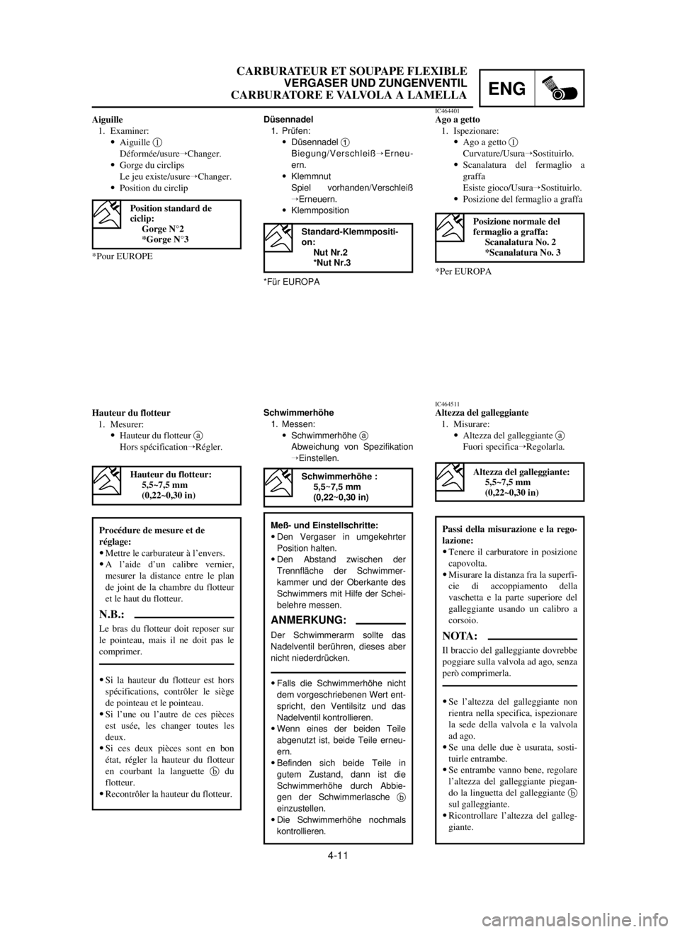
Aiguille
1. Examiner:
9Aiguille 1
Déformée/usureÕChanger.
9Gorge du circlips
Le jeu existe/usureÕChanger.
9Position du circlip
*Pour EUROPEDüsennadel
1. Prüfen:
9Düsennadel 1
Biegung/VerschleißÕErneu-
ern.
9Klemmnut
Spiel vorhanden/Verschleiß
ÕErneuern.
9Klemmposition
*Für EUROPAIC464401Ago a getto
1. Ispezionare:
9Ago a getto 1
Curvature/UsuraÕSostituirlo.
9Scanalatura del fermaglio a
graffa
Esiste gioco/UsuraÕSostituirlo.
9Posizione del fermaglio a graffa
*Per EUROPA
Standard-Klemmpositi-
on:
Nut Nr.2
*Nut Nr.3Posizione normale del
fermaglio a graffa:
Scanalatura No. 2
*Scanalatura No. 3
Position standard de
ciclip:
Gorge N°2
*Gorge N°3
Hauteur du flotteur
1. Mesurer:
9Hauteur du flotteur a
Hors spécificationÕRégler.Schwimmerhöhe
1. Messen:
9Schwimmerhöhe a
Abweichung von Spezifikation
ÕEinstellen.IC464511Altezza del galleggiante
1. Misurare:
9Altezza del galleggiante a
Fuori specificaÕRegolarla.
Schwimmerhöhe :
5,5~7,5 mm
(0,22~0,30 in)
Meß- und Einstellschritte:
9Den Vergaser in umgekehrter
Position halten.
9Den Abstand zwischen der
Trennfläche der Schwimmer-
kammer und der Oberkante des
Schwimmers mit Hilfe der Schei-
belehre messen.
ANMERKUNG:
Der Schwimmerarm sollte das
Nadelventil berühren, dieses aber
nicht niederdrücken.
9Falls die Schwimmerhöhe nicht
dem vorgeschriebenen Wert ent-
spricht, den Ventilsitz und das
Nadelventil kontrollieren.
9Wenn eines der beiden Teile
abgenutzt ist, beide Teile erneu-
ern.
9Befinden sich beide Teile in
gutem Zustand, dann ist die
Schwimmerhöhe durch Abbie-
gen der Schwimmerlasche b
einzustellen.
9Die Schwimmerhöhe nochmals
kontrollieren.
Altezza del galleggiante:
5,5~7,5 mm
(0,22~0,30 in)
Passi della misurazione e la rego-
lazione:
9Tenere il carburatore in posizione
capovolta.
9Misurare la distanza fra la superfi-
cie di accoppiamento della
vaschetta e la parte superiore del
galleggiante usando un calibro a
corsoio.
NOTA:
Il braccio del galleggiante dovrebbe
poggiare sulla valvola ad ago, senza
però comprimerla.
9Se l’altezza del galleggiante non
rientra nella specifica, ispezionare
la sede della valvola e la valvola
ad ago.
9Se una delle due è usurata, sosti-
tuirle entrambe.
9Se entrambe vanno bene, regolare
l’altezza del galleggiante piegan-
do la linguetta del galleggiante b
sul galleggiante.
9Ricontrollare l’altezza del galleg-
giante.
Hauteur du flotteur:
5,5~7,5 mm
(0,22~0,30 in)
Procédure de mesure et de
réglage:
9Mettre le carburateur à l’envers.
9A l’aide d’un calibre vernier,
mesurer la distance entre le plan
de joint de la chambre du flotteur
et le haut du flotteur.
N.B.:
Le bras du flotteur doit reposer sur
le pointeau, mais il ne doit pas le
comprimer.
9Si la hauteur du flotteur est hors
spécifications, contrôler le siège
de pointeau et le pointeau.
9Si l’une ou l’autre de ces pièces
est usée, les changer toutes les
deux.
9Si ces deux pièces sont en bon
état, régler la hauteur du flotteur
en courbant la languette bdu
flotteur.
9Recontrôler la hauteur du flotteur.
5MW-9-30-4A 7/3/00 5:04 PM Page 23
Page 234 of 578

ENG
4-12
CARBURETOR AND REED VALVE
EC465000
ASSEMBLY AND INSTALLATION
EC465171
Reed valve
1. Install:
9Reed valve 1
9Stopper (reed valve) 2
9Screw (reed valve) 3
NOTE:
9Install the reed valve with the reed valve bend-
ing as shown.
9Note the cut ain the lower corner of the reed
and stopper plate.
cC
Tighten each screw gradually to avoid
warping.
1 Nm (0.1 m•kg, 0.7 ft•lb)
9Valve stopper height b
Out of specification Õ Adjust stopper/
Replace valve stopper.
Valve stopper height:
10.3 ~10.7 mm (0.406~0.421 in)
EC464600
Float
1. Inspect:
9Float 1
Damage ÕReplace.
EC464701
Reed valve
1. Measure:
9Reed valve bending a
Out of specification ÕReplace.
Reed valve bending limit:
0.2 mm (0.008 in)
5MW-9-30-4A 7/3/00 5:05 PM Page 24
Page 235 of 578
ENG
4-12
CARBURATEUR ET SOUPAPE FLEXIBLE
VERGASER UND ZUNGENVENTIL
CARBURATORE E VALVOLA A LAMELLA
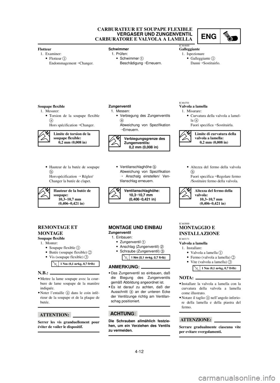
9Hauteur de la butée de soupape
b
Hors spécification ÕRégler/
Changer la butée de clapet.9Altezza del fermo della valvola
b
Fuori specificaÕRegolare fermo
/Sostituire fermo della valvola.
IC465000
MONTAGGIO E
INSTALLAZIONE
IC465171
Valvola a lamella
1. Installare:
9Valvola a lamella 1
9Fermo (valvola a lamella) 2
9Vite (valvola a lamella) 3
NOTA:
9Installare la valvola a lamella con la
curvatura della valvola a lamella
come illustrato.
9Notare il taglio anell’angolo inferio-
re della lamella e della piastra del
fermo.
iI
Serrare gradualmente ciascuna vite
per evitare svergolamenti.
9Ventilanschlaghöhe b
Abweichung von Spezifikation
Õ Anschalg einstellen/ Ven-
tilanschlag erneuern.
MONTAGE UND EINBAU
Zungenventil
1. Einbauen:
9Zungenventil 1
9Anschlag (Zungenventil) 2
9Schraube (Zungenventil) 3
ANMERKUNG:
9Das Zungenventil so einbauen, daß
die Biegung des Zungenventils
gemäß Abbildung angeordnet ist.
9Es ist darauf zu achten, daß der
Ausschnitt aan der unteren Ecke
der Ventilzunge richtig am Ventilan-
schag positioniert.
dD
Die Schrauben allmählich festzie-
hen, um ein Verziehen des Ventils
zu vermeiden.
REMONTAGE ET
MONTAGE
Soupape flexible
1. Monter:
9Soupape flexible 1
9Butée (soupape flexible) 2
9Vis (soupape flexible) 3
N.B.:
9Mettre la lame soupape avec la cour-
bure de lame soupape de la manière
indiquée.
9Noter l’entaille adans le coin infé-
rieur de la soupape et de la plaque de
butée.
fF
Serrer les vis granduellement pour
éviter de voiler le dispositif.
Ventilanschlaghöhe:
10,3~10,7 mm
(0,406~0,421 in)
1 Nm (0,1 m•kg, 0,7 ft•lb)
Altezza del fermo della
valvola:
10,3~10,7 mm
(0,406~0,421 in)
1 Nm (0,1 m•kg, 0,7 ft•lb)
1 Nm (0,1 m•kg, 0,7 ft•lb)
Hauteur de la butée de
soupape:
10,3~10,7 mm
(0,406~0,421 in)
IC464701Valvola a lamella
1. Misurare:
9Curvatura della valvola a lamel-
la a
Fuori specificaÕSostituirla.Zungenventil
1. Messen:
9Verbiegung des Zungenventils
a
Abweichung von Spezifikation
ÕErneuern. Schwimmer
1. Prüfen:
9Schwimmer 1
BeschädigungÕErneuern.
Flotteur
1. Examiner:
9Flotteur 1
EndommagementÕChanger.
Soupape flexible
1. Mesurer:
9Torsion de la soupape flexible
a
Hors spécificationÕChanger.IC464600Galleggiante
1. Ispezionare
9Galleggiante 1
DanniÕSostituirlo.
Verbiegungsgrenze des
Zungenventils:
0,2 mm (0,008 in)
Limite di curvatura della
valvola a lamella:
0,2 mm (0,008 in)Limite de torsion de la
soupape flexible:
0,2 mm (0,008 in)
5MW-9-30-4A 7/3/00 5:05 PM Page 25
Page 236 of 578
ENG
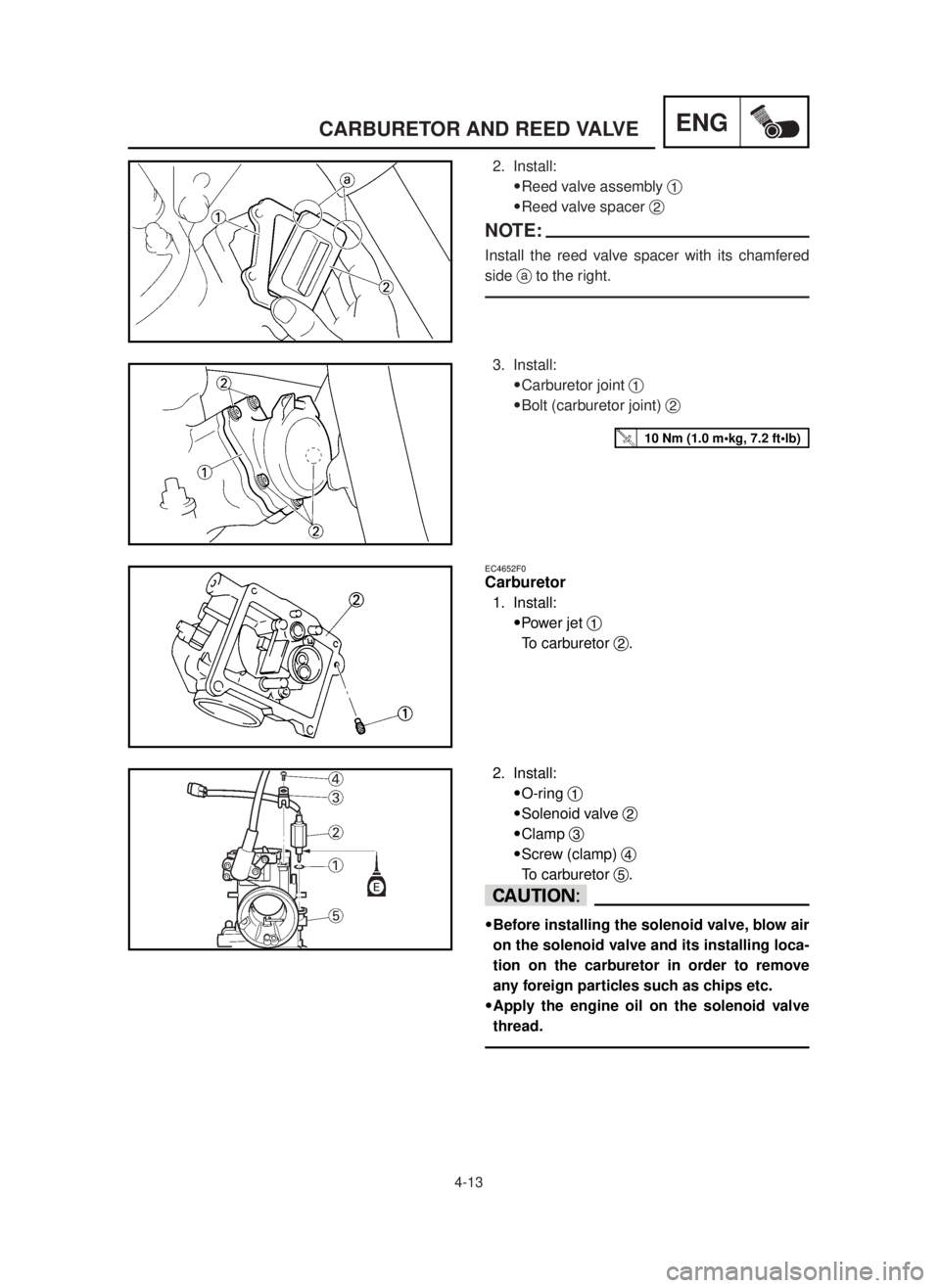
2. Install:
9Reed valve assembly 1
9Reed valve spacer 2
NOTE:
Install the reed valve spacer with its chamfered
side ato the right.
3. Install:
9Carburetor joint 1
9Bolt (carburetor joint) 2
4-13
CARBURETOR AND REED VALVE
10 Nm (1.0 m•kg, 7.2 ft•lb)
EC4652F0
Carburetor
1. Install:
9Power jet 1
To carburetor 2.
2. Install:
9O-ring 1
9Solenoid valve 2
9Clamp 3
9Screw (clamp) 4
To carburetor 5.
cC
9Before installing the solenoid valve, blow air
on the solenoid valve and its installing loca-
tion on the carburetor in order to remove
any foreign particles such as chips etc.
9Apply the engine oil on the solenoid valve
thread.
5MW-9-30-4A 7/3/00 5:24 PM Page 26
Page 237 of 578
ENG
4-13
CARBURATEUR ET SOUPAPE FLEXIBLE
VERGASER UND ZUNGENVENTIL
CARBURATORE E VALVOLA A LAMELLA
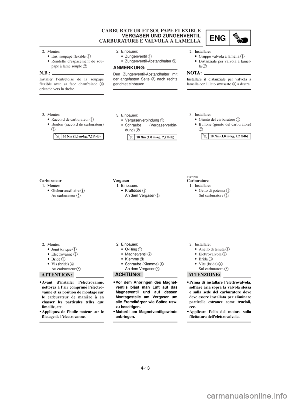
IC4652F0Carburatore
1. Installare:
9Getto di potenza 1
Sul carburatore 2.
2. Installare:
9Anello di tenuta 1
9Elettrovalvola 2
9Brida 3
9Vite (brida) 4
Sul carburatore 5.
iI
9Prima di installare l’elettrovalvola,
soffiare aria sopra la valvola stessa
e sulla sede del carburatore dove
deve essere installata per eliminare
particelle estranee come trucioli,
ecc.
9Applicare l’olio del motore sulla
filettatura dell’elettrovalvola.
Vergaser
1. Einbauen:
9Kraftdüse 1
An dem Vergaser 2.
2. Einbauen:
9O-Ring 1
9Magnetventil 2
9Klemme 3
9Schraube (Klemme) 4
An dem Vergaser 5.
dD
9Vor dem Anbringen des Magnet-
ventils bläst man Luft auf das
Magnetventil und auf dessen
Montagestelle am Vergaser um
alle Fremdkörper wie Späne usw.
zu beseitigen.
9Motoröl am Magnetventilgewinde
anbringen.
Carburateur
1. Monter:
9Gicleur auxiliaire 1
Au carburateur 2.
2. Monter:
9Joint torique 1
9Electrovanne 2
9Bride 3
9Vis (bride) 4
Au carburateur 5.
fF
9Avant d’installer l’électrovanne,
nettoyez à l’air comprimé l’électro-
vanne et sa position de montage sur
le carburateur de manière à en
chasser les particules telles que
limaille, etc.
9Appliquez de l’huile moteur sur le
filetage de l’électrovanne.
2. Installare:
9Gruppo valvola a lamella 1
9Distanziale per valvola a lamel-
la 2
NOTA:
Installare il distanziale per valvola a
lamella con il lato smussato aa destra.
3. Installare:
9Giunto del carburatore 1
9Bullone (giunto del carburatore)
23. Einbauen:
9Vergaserverbindung 1
9Schraube (Vergaserverbin-
dung) 2 2. Einbauen:
9Zungenventil 1
9Zungenventil-Abstandhalter 2
ANMERKUNG:
Den Zungenventil-Abstandhalter mit
der angefasten Seite anach rechts
gerichtet einbauen.
2. Monter:
9Ens. soupape flexible 1
9Rondelle d’espacement de sou-
pape à lame souple 2
N.B.:
Installer l’entretoise de la soupape
flexible avec sa face chanfreinée a
orientée vers la droite.
3. Monter:
9Raccord de carburateur 1
9Boulon (raccord de carburateur)
2
10 Nm (1,0 m•kg, 7,2 ft•lb)10 Nm (1,0 m•kg, 7,2 ft•lb)10 Nm (1,0 m•kg, 7,2 ft•lb)
5MW-9-30-4A 7/3/00 5:24 PM Page 27
Page 238 of 578

ENG
3. Install:
9Pilot air screw 1
9Throttle stop screw 2
*For EUROPE
4. Install:
9Starter plunger 1
4-14
CARBURETOR AND REED VALVE
Pilot air screw:
1 turn out
*1-3/4 turns out
(for reference only)
Note the following installation points:
9Turn in the pilot air screw until it is lightly
seated.
9Turn out the pilot air screw by the number of
turns recorded before removing.
5. Install:
9Pilot jet 1
9Main jet 2
6. Install:
9Needle valve 1
9Float 2
9Float pin 3
NOTE:
9After installing the needle valve to the float,
install them to the carburetor.
9Check the float for smooth movement.
7. Install:
9Float chamber 1
9Plate 2
9Screw (float chamber) 3
5MW-9-30-4A 7/3/00 5:24 PM Page 28
Page 239 of 578
ENG
4-14
CARBURATEUR ET SOUPAPE FLEXIBLE
VERGASER UND ZUNGENVENTIL
CARBURATORE E VALVOLA A LAMELLA
6. Einbauen:
9Nadelventil 1
9Schwimmer 2
9Schwimmerstift 3
ANMERKUNG:
9Nachdem das Nadelventil am
Schwimmer angebracht wurde,
diese Einheit in den Vergaser ein-
bauen.
9Den Schwimmer auf glatte Bewe-
gung prüfen.
6. Monter:
9Pointeau 1
9Flotteur 2
9Axe de flotteur 3
N.B.:
9Aprés avoir installé le pointeau sur le
flotteur, les installer sur le carbura-
teur.
9Vérifier que le flotteur bouge en dou-
ceur.
6. Installare:
9Valvola ad ago 1
9Galleggiante 2
9Perno del galleggiante 3
NOTA:
9Dopo avere installato la valvola ad
ago sul galleggiante, installarli sul
carburatore.
9Controllare che il galleggiante si
muova senza difficoltà.
7. Monter:
9Chambre du flotteur 1
9Plaque 2
9Vis (chambre du flotteur) 37. Einbauen:
9Schwimmerkammer 1
9Platte 2
9Schraube (Schwimmerkam-
mer) 37. Installare:
9Vaschetta 1
9Piastra 2
9Vite (vaschetta) 3 5. Monter:
9Gicleur de ralenti 1
9Gicleur principal 2
5. Einbauen:
9Leerlanfdüse 1
9Hauptdüse 25. Installare:
9Getto pilota 1
9Getto principale 2 3. Monter:
9Vis de richesse 1
9Vis butée d’accélérateur 2
*Pour EUROPE
4. Monter:
9Plongeur de démarreur 1 Noter les points de montage sui-
vants:
9Visser la vis de richesse jusqu’à
ce qu’elle touche légèrement son
siège.
9Dévisser la vis de richesse du
nombre de tours consigné préala-
blement à la dépose.
Vis de richesse:
1 tour en arrière
*1-3/4 tours en arrière
(référence uniquement)
3. Einbauen:
9Leerlauf-Luftregulierschraube
1
9Drosselanschlagschraube 2
*Für EUROPA
4. Einbauen:
9Starter-Plungerkolben 1 Die folgeden Einbaupunkte
beachten:
9Die Leerlauf-Luftregulierschrau-
be einschrauben, bis diese leicht
ansteht.
9Leerlauf-Luftregulierschraube
um die vor dem Ausbau aufge-
zeichnete Anzahl Umdrehungen
ausdrehen.
Leerlauf-Luftregulier-
schraube:
1 Ausdrehung
*1-3/4 Ausdrehungen
(nur als Hinweis)
3. Installare:
9Vite dell’aria pilota 1
9Vite di arresto della valvola a
farfalla 2
*Per EUROPA
4. Installare:
9Stantuffo dell’avviamento 1 Notare i seguenti punti di instal-
lazione:
9Avvitare la vite dell’aria pilota
finché non è alloggiata legger-
mente.
9Allentare la vite dell’aria pilota
del numero di giri registrato prima
della rimozione.
Vite dell’aria pilota:
Svitata di 1 giro
*Svitata di 1-3/4 di giro
(solo riferimento)
5MW-9-30-4A 7/3/00 5:25 PM Page 29
Page 240 of 578
![YAMAHA YZ250LC 2001 Notices Demploi (in French) ENG
4-15
CARBURETOR AND REED VALVE
8. Install:
9Air vent hose [
R=580 mm (22.8 in)] 1
9Air vent hose [R=400mm (15.7 in)] 2
9Overflow hose [R=280mm (11.0 in)] 3
9Clamp 4
NOTE:
Install the air vent hose YAMAHA YZ250LC 2001 Notices Demploi (in French) ENG
4-15
CARBURETOR AND REED VALVE
8. Install:
9Air vent hose [
R=580 mm (22.8 in)] 1
9Air vent hose [R=400mm (15.7 in)] 2
9Overflow hose [R=280mm (11.0 in)] 3
9Clamp 4
NOTE:
Install the air vent hose](/img/51/53969/w960_53969-239.png)
ENG
4-15
CARBURETOR AND REED VALVE
8. Install:
9Air vent hose [
R=580 mm (22.8 in)] 1
9Air vent hose [R=400mm (15.7 in)] 2
9Overflow hose [R=280mm (11.0 in)] 3
9Clamp 4
NOTE:
Install the air vent hoses and overflow hose to
the carburetor with their ends not having the cuts
atoward the carburetor.
9. Install:
9Jet needle 1
9Collar 2
9Spring 3
9Needle holder 4
To throttle valve 5.
NOTE:
Install the spring with its smaller dia. afacing
the collar.
10. Install:
9Throttle cable 1
9Mixing chamber top 2
9Spring (throttle valve) 3
9Ring 4
9Throttle valve 5
NOTE:
9While compressing the spring, connect the
throttle cable.
9Align the projection aon the ring with the
groove bin the needle holder 6.
5MW-9-30-4A 7/3/00 5:25 PM Page 30