YAMAHA YZ250LC 2007 Manuale duso (in Italian)
Manufacturer: YAMAHA, Model Year: 2007, Model line: YZ250LC, Model: YAMAHA YZ250LC 2007Pages: 596, PDF Dimensioni: 14.47 MB
Page 461 of 596
![YAMAHA YZ250LC 2007 Manuale duso (in Italian) 2. Installare:
9Manubrio 1
9Supporto del manubrio (supe-
riore) 2
9Bullone [supporto del manubrio
(superiore)] 32. Einbauen:
9Lenkstange 1
9Lenkerhalter (oben) 2
9Schraube [Lenkerhalter (oben)]
32. Mo YAMAHA YZ250LC 2007 Manuale duso (in Italian) 2. Installare:
9Manubrio 1
9Supporto del manubrio (supe-
riore) 2
9Bullone [supporto del manubrio
(superiore)] 32. Einbauen:
9Lenkstange 1
9Lenkerhalter (oben) 2
9Schraube [Lenkerhalter (oben)]
32. Mo](/img/51/53963/w960_53963-460.png)
2. Installare:
9Manubrio 1
9Supporto del manubrio (supe-
riore) 2
9Bullone [supporto del manubrio
(superiore)] 32. Einbauen:
9Lenkstange 1
9Lenkerhalter (oben) 2
9Schraube [Lenkerhalter (oben)]
32. Monter:
9Guidon 1
9Support de guidon (supérieur)
2
9Boulon [support de guidon
(supérieur)] 3
5-45
CHAS
GUIDON
LENKSTANGE
MANUBRIO
2. Einbauen:
9Griffkappe (oben) 1
9Griffkappe (unten) 2
9Schraube (Griffkappe) 3
HINWEIS:
Die Schrauben (Griffkappe) vorläufig
festziehen.
2. Monter:
9Capuchon de poignée (supé-
rieur) 1
9Capuchon de poignée (inférieur)
2
9Boulon (capuchon de poignée)
3
N.B.:
Serrer les boulons (capuchon de poi-
gnée) provisoirement.
2. Installare:
9Calotta della manopola (supe-
riore) 1
9Calotta della manopola (inferio-
re) 2
9Bullone (calotta della manopo-
la) 3
NOTA:
Serrare temporaneamente i bulloni (ca-
lotta della manopola).
28 Nm (2,8 m•kg, 20 ft•lb)28 Nm (2,8 m•kg, 20 ft•lb)28 Nm (2,8 m•kg, 20 ft•lb)
Guidon
1. Monter:
9Support de guidon (inférieur) 1
9Rondelle plate 2
9Ecrou [support de guidon (infé-
rieur)] 3
N.B.:
9Installer le support de guidon (infé-
rieur) avec le côté offrant la plus gran-
de distance apar rapport à l’axe du
boulon de montage orienté vers
l’avant.
9Appliquer de la graisse à base de
savon au lithium sur le filetage du
support de guidon (inférieur).
9L’installation du support de guidon
(inférieur) en sens inverse permet de
changer le décalage d’avant en arrière
de la position du guidon.
9Ne pas serrer l’écrou à ce stade.
Lenkstange
1. Einbauen:
9Lenkerhalter (unten) 1
9Unterlegscheibe 2
9Mutter [Lenkerhalter (unten)]
3
HINWEIS:
9Die Lenkerhalterung (unten) mit
nach vorne weisender Seite, die den
größeren Abstand avon der Mitte
der Befestigungsschraube aufweist,
einbauen.
9Lithium-Fett auf dem Gewinde des
Lenkerhalterung (unten) auftragen.
9Der Einbau der Lenkerhalterung
(unten) in umgekehrter Richtung
ermöglicht eine Änderung des Ver-
satzumfangs vorne-nach-hinten der
Lenkerposition.
9Die Mutter noch nicht festziehen.
IC5B5210
Manubrio
1. Installare:
9Supporto (inferiore) del manu-
brio 1
9Rondella piana 2
9Dado [supporto (inferiore) del
manubrio] 3
NOTA:
9Installare il supporto del manubrio
(inferiore) con il lato che dista a
maggiormente dal centro del bullone
di montaggio rivolto in avanti.
9Applicare il grasso a base di sapone di
litio sulla filettatura del supporto del
manubrio (inferiore).
9Installando in direzione opposta il
supporto del manubrio (inferiore) è
possibile modificare lo sfalsamento da
anteriore a posteriore della posizione
del manubrio.
9Non serrare ancora il dado.
1P8-9-32-5c 4/10/06 4:42 PM Page 9
Page 462 of 596
5-46
CHASHANDLEBAR
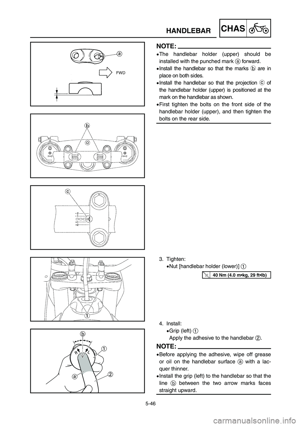
NOTE:
9The handlebar holder (upper) should be
installed with the punched mark aforward.
9Install the handlebar so that the marks bare in
place on both sides.
9Install the handlebar so that the projection cof
the handlebar holder (upper) is positioned at the
mark on the handlebar as shown.
9First tighten the bolts on the front side of the
handlebar holder (upper), and then tighten the
bolts on the rear side.
4. Install:
9Grip (left) 1
Apply the adhesive to the handlebar 2.
NOTE:
9Before applying the adhesive, wipe off grease
or oil on the handlebar surface awith a lac-
quer thinner.
9Install the grip (left) to the handlebar so that the
line bbetween the two arrow marks faces
straight upward.
3. Tighten:
9Nut [handlebar holder (lower)] 1
40 Nm (4.0 m•kg, 29 ft•lb)
1P8-9-32-5c 4/10/06 4:42 PM Page 10
Page 463 of 596
5-46
CHAS
GUIDON
LENKSTANGE
MANUBRIO
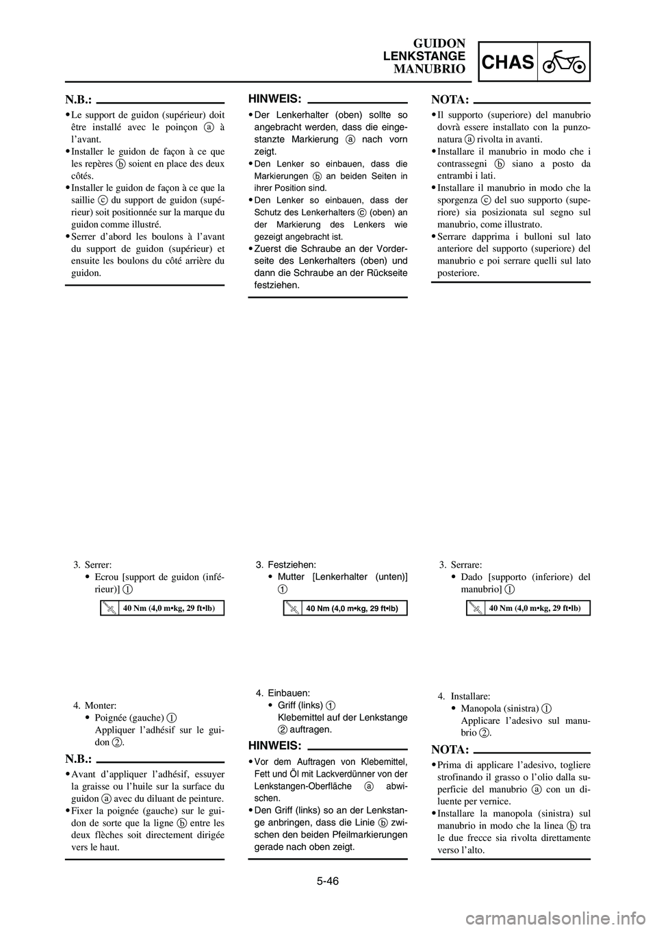
4. Monter:
9Poignée (gauche) 1
Appliquer l’adhésif sur le gui-
don 2.
N.B.:
9Avant d’appliquer l’adhésif, essuyer
la graisse ou l’huile sur la surface du
guidon aavec du diluant de peinture.
9Fixer la poignée (gauche) sur le gui-
don de sorte que la ligne bentre les
deux flèches soit directement dirigée
vers le haut.
4. Einbauen:
9Griff (links) 1
Klebemittel auf der Lenkstange
2auftragen.
HINWEIS:
9Vor dem Auftragen von Klebemittel,
Fett und Öl mit Lackverdünner von der
Lenkstangen-Oberfläche aabwi-
schen.
9Den Griff (links) so an der Lenkstan-
ge anbringen, dass die Linie bzwi-
schen den beiden Pfeilmarkierungen
gerade nach oben zeigt.
4. Installare:
9Manopola (sinistra) 1
Applicare l’adesivo sul manu-
brio 2.
NOTA:
9Prima di applicare l’adesivo, togliere
strofinando il grasso o l’olio dalla su-
perficie del manubrio acon un di-
luente per vernice.
9Installare la manopola (sinistra) sul
manubrio in modo che la linea btra
le due frecce sia rivolta direttamente
verso l’alto.
N.B.:
9Le support de guidon (supérieur) doit
être installé avec le poinçon aà
l’avant.
9
Installer le guidon de façon à ce que
les repères bsoient en place des deux
côtés.
9Installer le guidon de façon à ce que la
saillie cdu support de guidon (supé-
rieur) soit positionnée sur la marque du
guidon comme illustré.
9Serrer d’abord les boulons à l’avant
du support de guidon (supérieur) et
ensuite les boulons du côté arrière du
guidon.
HINWEIS:
9Der Lenkerhalter (oben) sollte so
angebracht werden, dass die einge-
stanzte Markierung anach vorn
zeigt.
9
Den Lenker so einbauen, dass die
Markierungen ban beiden Seiten in
ihrer Position sind.
9Den Lenker so einbauen, dass der
Schutz des Lenkerhalters c(oben) an
der Markierung des Lenkers wie
gezeigt angebracht ist.
9Zuerst die Schraube an der Vorder-
seite des Lenkerhalters (oben) und
dann die Schraube an der Rückseite
festziehen.
NOTA:
9Il supporto (superiore) del manubrio
dovrà essere installato con la punzo-
natura arivolta in avanti.
9Installare il manubrio in modo che i
contrassegni bsiano a posto da
entrambi i lati.
9Installare il manubrio in modo che la
sporgenza cdel suo supporto (supe-
riore) sia posizionata sul segno sul
manubrio, come illustrato.
9Serrare dapprima i bulloni sul lato
anteriore del supporto (superiore) del
manubrio e poi serrare quelli sul lato
posteriore.
3. Serrer:
9Ecrou [support de guidon (infé-
rieur)] 13. Festziehen:
9Mutter [Lenkerhalter (unten)]
13. Serrare:
9Dado [supporto (inferiore) del
manubrio] 1
40 Nm (4,0 m•kg, 29 ft•lb)40 Nm (4,0 m•kg, 29 ft•lb)40 Nm (4,0 m•kg, 29 ft•lb)
1P8-9-32-5c 4/10/06 4:42 PM Page 11
Page 464 of 596
5-47
CHASHANDLEBAR
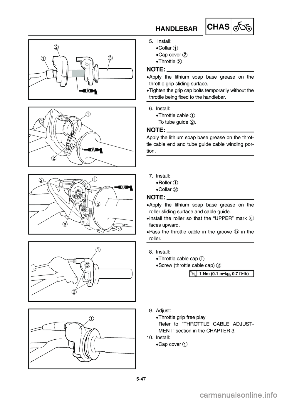
7. Install:
9Roller 1
9Collar 2
NOTE:
9Apply the lithium soap base grease on the
roller sliding surface and cable guide.
9Install the roller so that the “UPPER” mark a
faces upward.
9Pass the throttle cable in the groove bin the
roller.
8. Install:
9Throttle cable cap 1
9Screw (throttle cable cap) 2
9. Adjust:
9Throttle grip free play
Refer to ”THROTTLE CABLE ADJUST-
MENT” section in the CHAPTER 3.
10. Install:
9Cap cover 1
1 Nm (0.1 m•kg, 0.7 ft•lb)
6. Install:
9Throttle cable 1
To tube guide 2.
NOTE:
Apply the lithium soap base grease on the throt-
tle cable end and tube guide cable winding por-
tion.
5. Install:
9Collar 1
9Cap cover 2
9Throttle 3
NOTE:
9Apply the lithium soap base grease on the
throttle grip sliding surface.
9Tighten the grip cap bolts temporarily without the
throttle being fixed to the handlebar.
1P8-9-32-5c 4/10/06 4:42 PM Page 12
Page 465 of 596
5-47
CHAS
GUIDON
LENKSTANGE
MANUBRIO
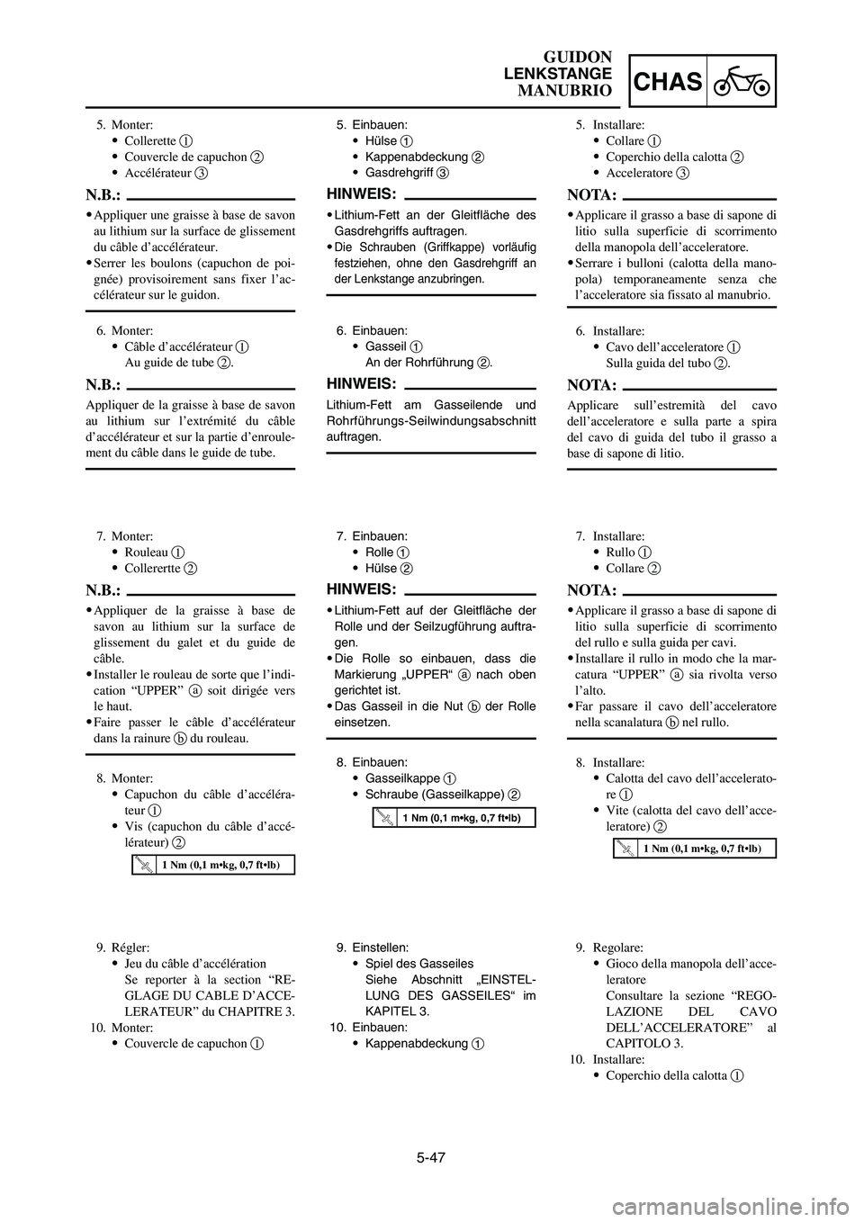
7. Einbauen:
9Rolle 1
9Hülse 2
HINWEIS:
9Lithium-Fett auf der Gleitfläche der
Rolle und der Seilzugführung auftra-
gen.
9Die Rolle so einbauen, dass die
Markierung „UPPER“ anach oben
gerichtet ist.
9Das Gasseil in die Nut bder Rolle
einsetzen.
8. Einbauen:
9Gasseilkappe 1
9Schraube (Gasseilkappe) 2
7. Monter:
9Rouleau 1
9Collerertte 2
N.B.:
9Appliquer de la graisse à base de
savon au lithium sur la surface de
glissement du galet et du guide de
câble.
9Installer le rouleau de sorte que l’indi-
cation “UPPER” asoit dirigée vers
le haut.
9Faire passer le câble d’accélérateur
dans la rainure bdu rouleau.
8. Monter:
9Capuchon du câble d’accéléra-
teur 1
9Vis (capuchon du câble d’accé-
lérateur) 27. Installare:
9Rullo 1
9Collare 2
NOTA:
9Applicare il grasso a base di sapone di
litio sulla superficie di scorrimento
del rullo e sulla guida per cavi.
9Installare il rullo in modo che la mar-
catura “UPPER” asia rivolta verso
l’alto.
9Far passare il cavo dell’acceleratore
nella scanalatura bnel rullo.
8. Installare:
9Calotta del cavo dell’accelerato-
re 1
9Vite (calotta del cavo dell’acce-
leratore) 2
1 Nm (0,1 m•kg, 0,7 ft•lb)
1 Nm (0,1 m•kg, 0,7 ft•lb)
1 Nm (0,1 m•kg, 0,7 ft•lb)
5. Monter:
9Collerette 1
9Couvercle de capuchon 2
9Accélérateur 3
N.B.:
9Appliquer une graisse à base de savon
au lithium sur la surface de glissement
du câble d’accélérateur.
9Serrer les boulons (capuchon de poi-
gnée) provisoirement sans fixer l’ac-
célérateur sur le guidon.
5. Einbauen:
9Hülse 1
9Kappenabdeckung 2
9Gasdrehgriff 3
HINWEIS:
9Lithium-Fett an der Gleitfläche des
Gasdrehgriffs auftragen.
9
Die Schrauben (Griffkappe) vorläufig
festziehen, ohne den Gasdrehgriff an
der Lenkstange anzubringen.
5. Installare:
9Collare 1
9Coperchio della calotta 2
9Acceleratore 3
NOTA:
9Applicare il grasso a base di sapone di
litio sulla superficie di scorrimento
della manopola dell’acceleratore.
9Serrare i bulloni (calotta della mano-
pola) temporaneamente senza che
l’acceleratore sia fissato al manubrio.
6. Installare:
9Cavo dell’acceleratore 1
Sulla guida del tubo 2.
NOTA:
Applicare sull’estremità del cavo
dell’acceleratore e sulla parte a spira
del cavo di guida del tubo il grasso a
base di sapone di litio.
6. Einbauen:
9Gasseil 1
An der Rohrführung 2.
HINWEIS:
Lithium-Fett am Gasseilende und
Rohrführungs-Seilwindungsabschnitt
auftragen.
6. Monter:
9Câble d’accélérateur 1
Au guide de tube 2.
N.B.:
Appliquer de la graisse à base de savon
au lithium sur l’extrémité du câble
d’accélérateur et sur la partie d’enroule-
ment du câble dans le guide de tube.
9. Régler:
9Jeu du câble d’accélération
Se reporter à la section “RE-
GLAGE DU CABLE D’ACCE-
LERATEUR” du CHAPITRE 3.
10. Monter:
9Couvercle de capuchon 19. Einstellen:
9Spiel des Gasseiles
Siehe Abschnitt „EINSTEL-
LUNG DES GASSEILES“ im
KAPITEL 3.
10. Einbauen:
9Kappenabdeckung 19. Regolare:
9Gioco della manopola dell’acce-
leratore
Consultare la sezione “REGO-
LAZIONE DEL CAVO
DELL’ACCELERATORE” al
CAPITOLO 3.
10. Installare:
9Coperchio della calotta 1
1P8-9-32-5c 4/10/06 4:42 PM Page 13
Page 466 of 596
5-48
CHASHANDLEBAR
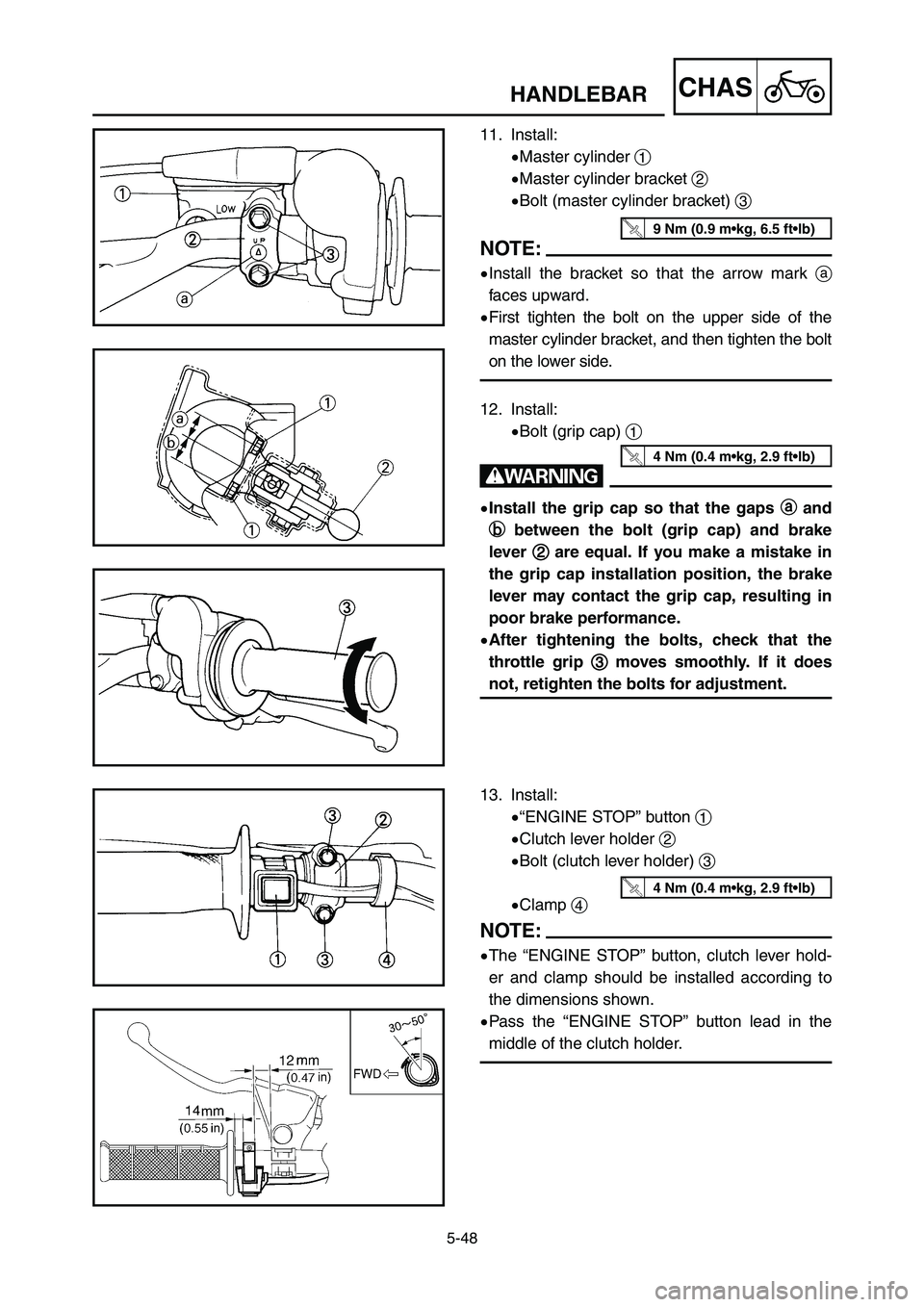
13. Install:
9“ENGINE STOP” button 1
9Clutch lever holder 2
9Bolt (clutch lever holder) 3
9Clamp 4
NOTE:
9The “ENGINE STOP” button, clutch lever hold-
er and clamp should be installed according to
the dimensions shown.
9Pass the “ENGINE STOP” button lead in the
middle of the clutch holder.
4 Nm (0.4 m•kg, 2.9 ft•lb)
12. Install:
9Bolt (grip cap) 1
w
9Install the grip cap so that the gaps a a
and
b b
between the bolt (grip cap) and brake
lever 2 2
are equal. If you make a mistake in
the grip cap installation position, the brake
lever may contact the grip cap, resulting in
poor brake performance.
9After tightening the bolts, check that the
throttle grip 3 3
moves smoothly. If it does
not, retighten the bolts for adjustment.
4 Nm (0.4 m•kg, 2.9 ft•lb)
11. Install:
9Master cylinder 1
9Master cylinder bracket 2
9Bolt (master cylinder bracket) 3
NOTE:
9Install the bracket so that the arrow mark a
faces upward.
9First tighten the bolt on the upper side of the
master cylinder bracket, and then tighten the bolt
on the lower side.
9 Nm (0.9 m•kg, 6.5 ft•lb)
1P8-9-32-5c 4/10/06 4:42 PM Page 14
Page 467 of 596
5-48
CHAS
GUIDON
LENKSTANGE
MANUBRIO
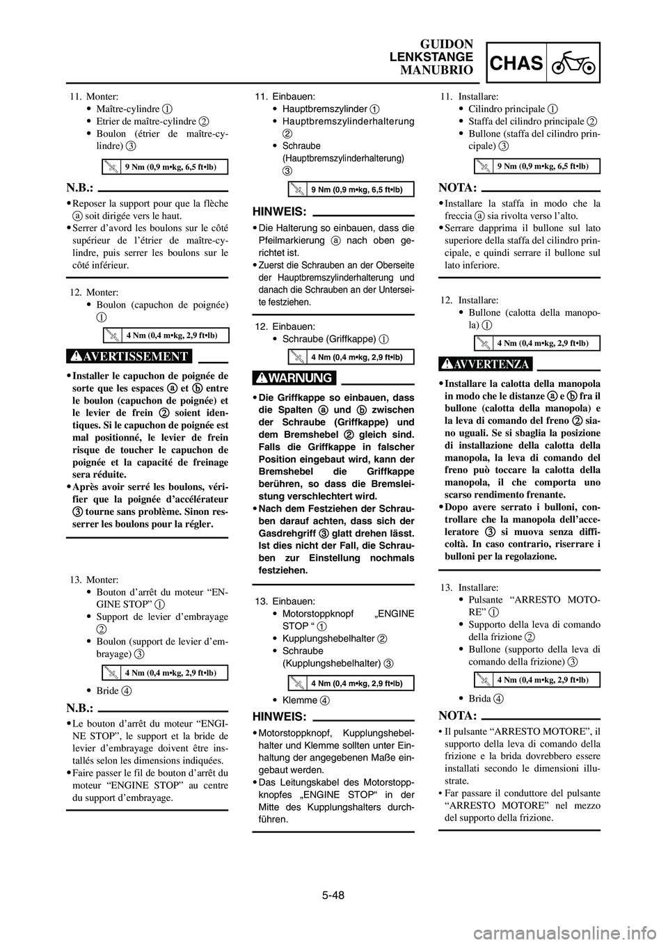
11. Einbauen:
9Hauptbremszylinder 1
9
Hauptbremszylinderhalterung
2
9
Schraube
(Hauptbremszylinderhalterung)
3
HINWEIS:
9Die Halterung so einbauen, dass die
Pfeilmarkierung anach oben ge-
richtet ist.
9
Zuerst die Schrauben an der Oberseite
der Hauptbremszylinderhalterung und
danach die Schrauben an der Untersei-
te festziehen.
11. Monter:
9Maître-cylindre 1
9Etrier de maître-cylindre 2
9Boulon (étrier de maître-cy-
lindre) 3
N.B.:
9Reposer la support pour que la flèche
asoit dirigée vers le haut.
9Serrer d’avord les boulons sur le côté
supérieur de l’étrier de maître-cy-
lindre, puis serrer les boulons sur le
côté inférieur.
12. Einbauen:
9Schraube (Griffkappe) 1
W
9Die Griffkappe so einbauen, dass
die Spalten a a
und b b
zwischen
der Schraube (Griffkappe) und
dem Bremshebel 2 2
gleich sind.
Falls die Griffkappe in falscher
Position eingebaut wird, kann der
Bremshebel die Griffkappe
berühren, so dass die Bremslei-
stung verschlechtert wird.
9Nach dem Festziehen der Schrau-
ben darauf achten, dass sich der
Gasdrehgriff 3 3
glatt drehen lässt.
Ist dies nicht der Fall, die Schrau-
ben zur Einstellung nochmals
festziehen.
13. Einbauen:
9Motorstoppknopf „ENGINE
STOP “ 1
9Kupplungshebelhalter 2
9Schraube
(Kupplungshebelhalter) 3
9Klemme 4
HINWEIS:
9Motorstoppknopf, Kupplungshebel-
halter und Klemme sollten unter Ein-
haltung der angegebenen Maße ein-
gebaut werden.
9Das Leitungskabel des Motorstopp-
knopfes „ENGINE STOP“ in der
Mitte des Kupplungshalters durch-
führen.
12. Monter:
9Boulon (capuchon de poignée)
1
XG
9Installer le capuchon de poignée de
sorte que les espaces a a
et b b
entre
le boulon (capuchon de poignée) et
le levier de frein 2 2
soient iden-
tiques. Si le capuchon de poignée est
mal positionné, le levier de frein
risque de toucher le capuchon de
poignée et la capacité de freinage
sera réduite.
9Après avoir serré les boulons, véri-
fier que la poignée d’accélérateur
3 3
tourne sans problème. Sinon res-
serrer les boulons pour la régler.
13. Monter:
9Bouton d’arrêt du moteur “EN-
GINE STOP” 1
9Support de levier d’embrayage
2
9Boulon (support de levier d’em-
brayage) 3
9Bride 4
N.B.:
9Le bouton d’arrêt du moteur “ENGI-
NE STOP”, le support et la bride de
levier d’embrayage doivent être ins-
tallés selon les dimensions indiquées.
9Faire passer le fil de bouton d’arrêt du
moteur “ENGINE STOP” au centre
du support d’embrayage.
12. Installare:
9Bullone (calotta della manopo-
la) 1
T
9Installare la calotta della manopola
in modo che le distanze a a
e b b
fra il
bullone (calotta della manopola) e
la leva di comando del freno 2 2
sia-
no uguali. Se si sbaglia la posizione
di installazione della calotta della
manopola, la leva di comando del
freno può toccare la calotta della
manopola, il che comporta uno
scarso rendimento frenante.
9Dopo avere serrato i bulloni, con-
trollare che la manopola dell’acce-
leratore 3 3
si muova senza diffi-
coltà. In caso contrario, riserrare i
bulloni per la regolazione.
13. Installare:
9Pulsante “ARRESTO MOTO-
RE” 1
9Supporto della leva di comando
della frizione 2
9Bullone (supporto della leva di
comando della frizione) 3
9Brida 4
NOTA:
• Il pulsante “ARRESTO MOTORE”, il
supporto della leva di comando della
frizione e la brida dovrebbero essere
installati secondo le dimensioni illu-
strate.
• Far passare il conduttore del pulsante
“ARRESTO MOTORE” nel mezzo
del supporto della frizione.
4 Nm (0,4 m•kg, 2,9 ft•lb)
4 Nm (0,4 m•kg, 2,9 ft•lb)
4 Nm (0,4 m•kg, 2,9 ft•lb)
4 Nm (0,4 m•kg, 2,9 ft•lb)4 Nm (0,4 m•kg, 2,9 ft•lb)4 Nm (0,4 m•kg, 2,9 ft•lb)
9 Nm (0,9 m•kg, 6,5 ft•lb)
9 Nm (0,9 m•kg, 6,5 ft•lb)
11. Installare:
9Cilindro principale 1
9Staffa del cilindro principale 2
9Bullone (staffa del cilindro prin-
cipale) 3
NOTA:
9Installare la staffa in modo che la
freccia asia rivolta verso l’alto.
9Serrare dapprima il bullone sul lato
superiore della staffa del cilindro prin-
cipale, e quindi serrare il bullone sul
lato inferiore.
9 Nm (0,9 m•kg, 6,5 ft•lb)
1P8-9-32-5c 4/10/06 4:42 PM Page 15
Page 468 of 596
5-49
CHASHANDLEBAR
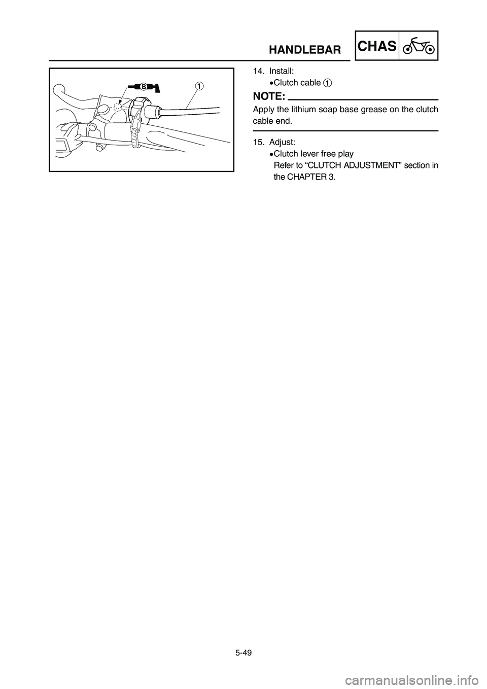
14. Install:
9Clutch cable 1
NOTE:
Apply the lithium soap base grease on the clutch
cable end.
15. Adjust:
9Clutch lever free play
Refer to “CLUTCH ADJUSTMENT” section in
the CHAPTER 3.
1P8-9-32-5c 4/10/06 4:42 PM Page 16
Page 469 of 596
5-49
CHAS
GUIDON
LENKSTANGE
MANUBRIO
14. Monter:
9Câble d’embrayage 1
N.B.:
Appliquer de la graisse à base de savon
au lithium sur l’extrémité du câble
d’embrayage.
15. Régler:
9Jeu du levier d’embrayage
Se reporter à la section “RE-
GLAGE DE L’EMBRAYAGE”
du CHAPITRE 3.
14. Einbauen:
9Kupplungskabel 1
HINWEIS:
Lithium-Fett am Kupplungskabelende
auftragen.
15. Einstellen:
9Spiel des Kupplungshebels
Siehe Abschnitt „EINSTEL-
LUNG DER KUPPLUNG“ im
KAPITEL 3.
14. Installare:
9Cavo della frizione 1
NOTA:
Applicare sull’estremità del cavo della
frizione il grasso a base di sapone di li-
tio.
15. Regolare:
9Gioco della leva di comando
della frizione
Consultare la sezione “REGO-
LAZIONE DELLA FRIZIO-
NE” al CAPITOLO 3.
1P8-9-32-5c 4/10/06 4:42 PM Page 17
Page 470 of 596
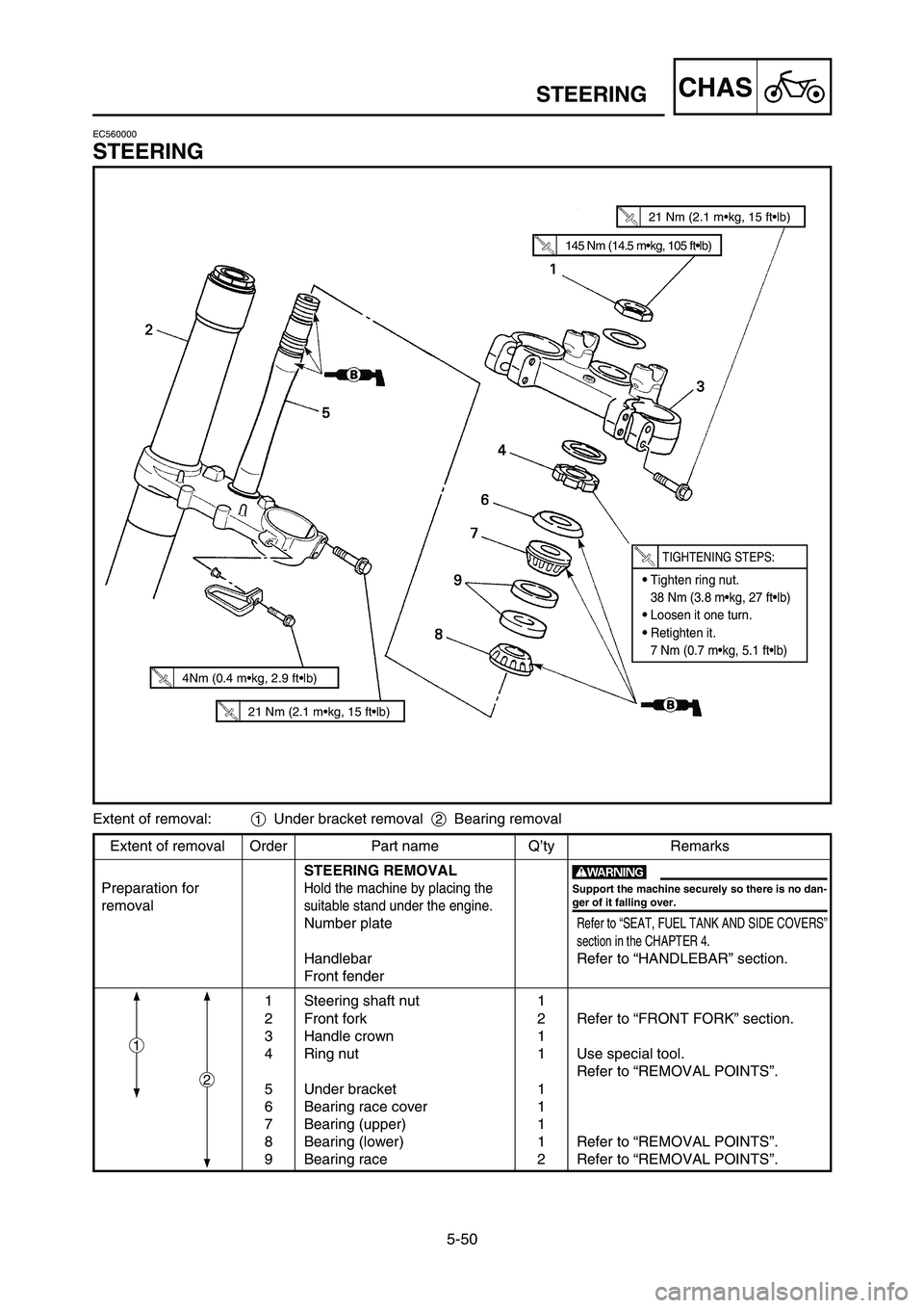
5-50
CHASSTEERING
Extent of removal Order Part name Q’ty Remarks
STEERING REMOVAL
Preparation for
Hold the machine by placing the
removalsuitable stand under the engine.
Number plateRefer to “SEAT, FUEL TANK AND SIDE COVERS”
section in the CHAPTER 4.
Handlebar Refer to “HANDLEBAR” section.
Front fender
1 Steering shaft nut 1
2 Front fork 2 Refer to “FRONT FORK” section.
3 Handle crown 1
4 Ring nut 1 Use special tool.
Refer to “REMOVAL POINTS”.
5 Under bracket 1
6 Bearing race cover 1
7 Bearing (upper) 1
8 Bearing (lower) 1 Refer to “REMOVAL POINTS”.
9 Bearing race 2 Refer to “REMOVAL POINTS”. Extent of removal:1Under bracket removal 2Bearing removal
2
1
w
Support the machine securely so there is no dan-
ger of it falling over.
EC560000
STEERING
145 Nm (14.5 m•kg, 105 ft•lb)
21 Nm (2.1 m•kg, 15 ft•lb)
9Tighten ring nut.
38 Nm (3.8 m•kg, 27 ft•lb)
9Loosen it one turn.
9Retighten it.
7 Nm (0.7 m•kg, 5.1 ft•lb)
TIGHTENING STEPS:
21 Nm (2.1 m•kg, 15 ft•lb)
4Nm (0.4 m•kg, 2.9 ft•lb)
1P8-9-32-5c 4/10/06 4:42 PM Page 18