YAMAHA YZ250LC 2007 Notices Demploi (in French)
Manufacturer: YAMAHA, Model Year: 2007, Model line: YZ250LC, Model: YAMAHA YZ250LC 2007Pages: 596, PDF Size: 14.47 MB
Page 341 of 596
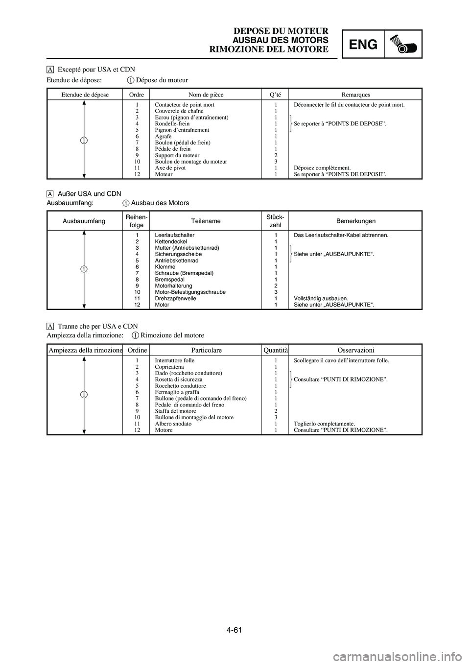
4-61
DEPOSE DU MOTEUR
AUSBAU DES MOTORS
RIMOZIONE DEL MOTOREENG
AusbauumfangReihen-
TeilenameStück-
Bemerkungenfolge zahl
1 Leerlaufschalter 1 Das Leerlaufschalter-Kabel abtrennen.
2 Kettendeckel 1
3 Mutter (Antriebskettenrad) 1
4 Sicherungsscheibe 1 Siehe unter „AUSBAUPUNKTE“.
5 Antriebskettenrad 1
6 Klemme 1
7 Schraube (Bremspedal) 1
8 Bremspedal 1
9 Motorhalterung 2
10 Motor-Befestigungsschraube 3
11 Drehzapfenwelle 1 Vollständig ausbauen.
12 Motor 1 Siehe unter „AUSBAUPUNKTE“.
Ausbauumfang:1Ausbau des Motors
Etendue de dépose:1Dépose du moteur
Etendue de dépose Ordre Nom de pièce Q’té Remarques
1 Contacteur de point mort 1 Déconnecter le fil du contacteur de point mort.
2 Couvercle de chaîne 1
3 Ecrou (pignon d’entraînement) 1
4 Rondelle-frein 1 Se reporter à “POINTS DE DEPOSE”.
5 Pignon d’entraînement 1
6 Agrafe 1
7 Boulon (pédal de frein) 1
8 Pédale de frein 1
9 Support du moteur 2
10 Boulon de montage du moteur 3
11 Axe de pivot 1 Déposez complètement.
12 Moteur 1 Se reporter à “POINTS DE DEPOSE”.
Ampiezza della rimozione:1Rimozione del motore
Ampiezza della rimozione Ordine Particolare Quantità Osservazioni
1 Interruttore folle 1 Scollegare il cavo dell’interruttore folle.
2 Copricatena 1
3 Dado (rocchetto conduttore) 1
4 Rosetta di sicurezza 1 Consultare “PUNTI DI RIMOZIONE”.
5 Rocchetto conduttore 1
6 Fermaglio a graffa 1
7 Bullone (pedale di comando del freno) 1
8 Pedale di comando del freno 1
9 Staffa del motore 2
10 Bullone di montaggio del motore 3
11 Albero snodato 1 Toglierlo completamente.
12 Motore 1 Consultare “PUNTI DI RIMOZIONE”.
1
1
1
åAußer USA und CDN
åTranne che per USA e CDN åExcepté pour USA et CDN
1P8-9-32-4c 5/1/06 10:46 AM Page 25
Page 342 of 596
4-62
ENGINE REMOVALENG
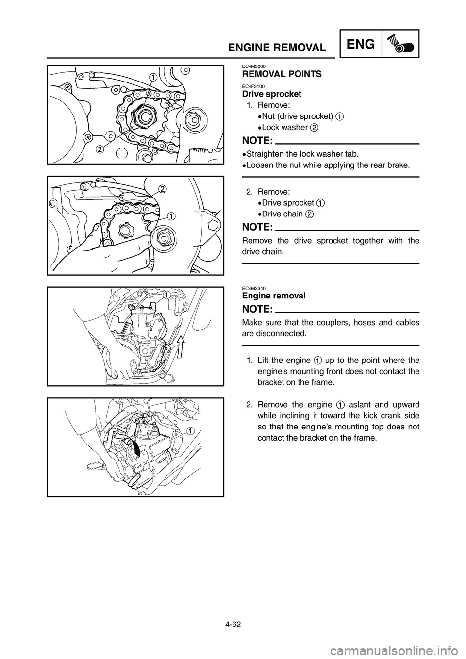
EC4M3340
Engine removal
NOTE:
Make sure that the couplers, hoses and cables
are disconnected.
1. Lift the engine 1up to the point where the
engine’s mounting front does not contact the
bracket on the frame.
2. Remove the engine 1aslant and upward
while inclining it toward the kick crank side
so that the engine’s mounting top does not
contact the bracket on the frame.
EC4M3000
REMOVAL POINTS
EC4F3100
Drive sprocket
1. Remove:
9Nut (drive sprocket) 1
9Lock washer 2
NOTE:
9Straighten the lock washer tab.
9Loosen the nut while applying the rear brake.
2. Remove:
9Drive sprocket 1
9Drive chain 2
NOTE:
Remove the drive sprocket together with the
drive chain.
1P8-9-32-4c 5/1/06 10:46 AM Page 26
Page 343 of 596
4-62
DEPOSE DU MOTEUR
AUSBAU DES MOTORS
RIMOZIONE DEL MOTOREENG
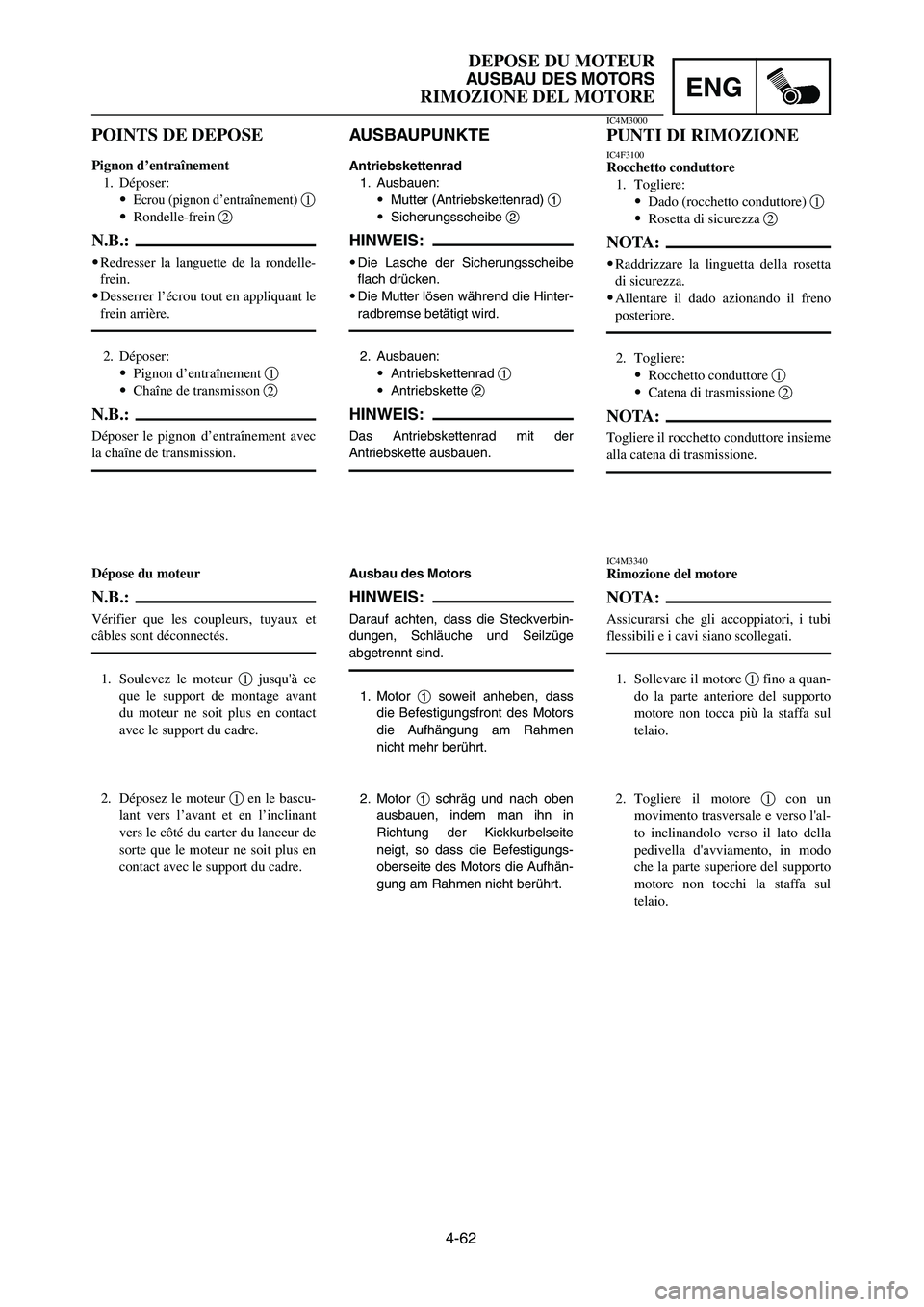
AUSBAUPUNKTE
Antriebskettenrad
1. Ausbauen:
9Mutter (Antriebskettenrad) 1
9Sicherungsscheibe 2
HINWEIS:
9Die Lasche der Sicherungsscheibe
flach drücken.
9Die Mutter lösen während die Hinter-
radbremse betätigt wird.
2. Ausbauen:
9Antriebskettenrad 1
9Antriebskette 2
HINWEIS:
Das Antriebskettenrad mit der
Antriebskette ausbauen.
Ausbau des Motors
HINWEIS:
Darauf achten, dass die Steckverbin-
dungen, Schläuche und Seilzüge
abgetrennt sind.
1. Motor 1soweit anheben, dass
die Befestigungsfront des Motors
die Aufhängung am Rahmen
nicht mehr berührt.
2. Motor 1schräg und nach oben
ausbauen, indem man ihn in
Richtung der Kickkurbelseite
neigt, so dass die Befestigungs-
oberseite des Motors die Aufhän-
gung am Rahmen nicht berührt.
IC4M3000
PUNTI DI RIMOZIONE
IC4F3100Rocchetto conduttore
1. Togliere:
9Dado (rocchetto conduttore) 1
9Rosetta di sicurezza 2
NOTA:
9Raddrizzare la linguetta della rosetta
di sicurezza.
9Allentare il dado azionando il freno
posteriore.
2. Togliere:
9Rocchetto conduttore 1
9Catena di trasmissione 2
NOTA:
Togliere il rocchetto conduttore insieme
alla catena di trasmissione.
IC4M3340Rimozione del motore
NOTA:
Assicurarsi che gli accoppiatori, i tubi
flessibili e i cavi siano scollegati.
1. Sollevare il motore 1fino a quan-
do la parte anteriore del supporto
motore non tocca più la staffa sul
telaio.
2. Togliere il motore 1con un
movimento trasversale e verso l'al-
to inclinandolo verso il lato della
pedivella d'avviamento, in modo
che la parte superiore del supporto
motore non tocchi la staffa sul
telaio.
POINTS DE DEPOSE
Pignon d’entraînement
1. Déposer:
9
Ecrou (pignon d’entraînement) 1
9Rondelle-frein 2
N.B.:
9Redresser la languette de la rondelle-
frein.
9Desserrer l’écrou tout en appliquant le
frein arrière.
2. Déposer:
9Pignon d’entraînement 1
9Chaîne de transmisson 2
N.B.:
Déposer le pignon d’entraînement avec
la chaîne de transmission.
Dépose du moteur
N.B.:
Vérifier que les coupleurs, tuyaux et
câbles sont déconnectés.
1. Soulevez le moteur 1jusqu'à ce
que le support de montage avant
du moteur ne soit plus en contact
avec le support du cadre.
2. Déposez le moteur 1en le bascu-
lant vers l’avant et en l’inclinant
vers le côté du carter du lanceur de
sorte que le moteur ne soit plus en
contact avec le support du cadre.
1P8-9-32-4c 5/1/06 10:46 AM Page 27
Page 344 of 596
4-63
ENGINE REMOVALENG
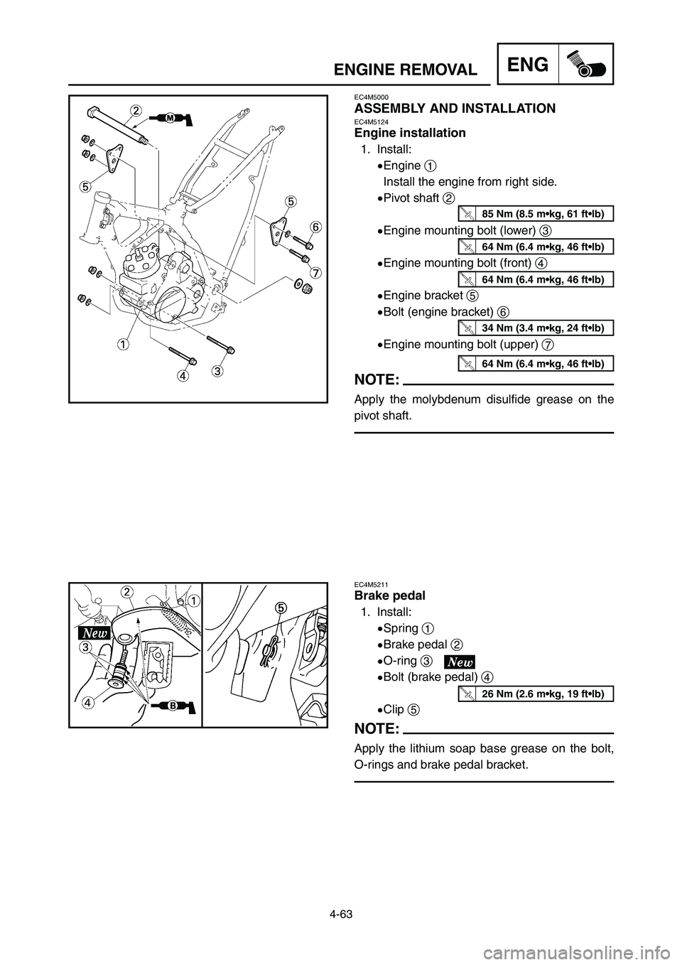
EC4M5211
Brake pedal
1. Install:
9Spring 1
9Brake pedal 2
9O-ring 3
9Bolt (brake pedal) 4
9Clip 5
NOTE:
Apply the lithium soap base grease on the bolt,
O-rings and brake pedal bracket.
EC4M5000
ASSEMBLY AND INSTALLATIONEC4M5124
Engine installation
1. Install:
9Engine 1
Install the engine from right side.
9Pivot shaft 2
9Engine mounting bolt (lower) 3
9Engine mounting bolt (front) 4
9Engine bracket 5
9Bolt (engine bracket) 6
9Engine mounting bolt (upper) 7
NOTE:
Apply the molybdenum disulfide grease on the
pivot shaft.
85 Nm (8.5 m•kg, 61 ft•lb)
64 Nm (6.4 m•kg, 46 ft•lb)
64 Nm (6.4 m•kg, 46 ft•lb)
34 Nm (3.4 m•kg, 24 ft•lb)
64 Nm (6.4 m•kg, 46 ft•lb)
26 Nm (2.6 m•kg, 19 ft•lb)
1P8-9-32-4c 5/1/06 10:46 AM Page 28
Page 345 of 596
4-63
DEPOSE DU MOTEUR
AUSBAU DES MOTORS
RIMOZIONE DEL MOTOREENG
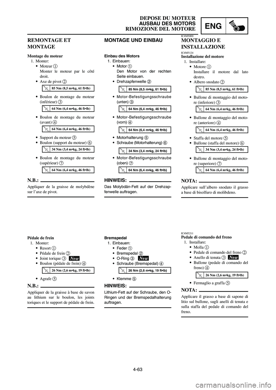
MONTAGE UND EINBAU
Einbau des Motors
1. Einbauen:
9Motor 1
Den Motor von der rechten
Seite einbauen.
9Drehzapfenwelle 2
9
Motor-Befestigungsschraube
(unten)
3
9Motor-Befestigungsschraube
(vorn) 4
9Motorhalterung 5
9Schraube (Motorhalterung) 6
9
Motor-Befestigungsschraube
(oben)
7
HINWEIS:
Das Molybdän-Fett auf der Drehzap-
fenwelle auftragen.
Bremspedal
1. Einbauen:
9Feder 1
9Bremspedal 2
9O-Ring 3
9Schraube (Bremspedal) 4
9Klemme 5
HINWEIS:
Lithium-Fett auf der Schraube, den O-
Ringen und der Bremspedalhalterung
auftragen.
REMONTAGE ET
MONTAGE
Montage du moteur
1. Monter:
9Moteur 1
Monter le moteur par le côté
droit.
9Axe de pivot 2
9Boulon de montage du moteur
(inférieur) 3
9Boulon de montage du moteur
(avant) 4
9Support du moteur 5
9Boulon (support du moteur) 6
9Boulon de montage du moteur
(supérieur) 7
N.B.:
Appliquer de la graisse de molybdène
sur l’axe de pivot.
Pédale de frein
1. Monter:
9Resort 1
9Pédale de frein 2
9Joint torique 3
9Boulon (pédale de frein) 4
9Agrafe 5
N.B.:
Appliquer de la graisse à base de savon
au lithium sur le boulon, les joints
toriques et le support de pédale de frein.
IC4M5000
MONTAGGIO E
INSTALLAZIONE
IC4M5124Installazione del motore
1. Installare:
9Motore 1
Installare il motore dal lato
destro.
9Albero snodato 2
9Bullone di montaggio del moto-
re (inferiore) 3
9Bullone di montaggio del moto-
re (anteriore) 4
9Staffa del motore 5
9Bullone (staffa del motore) 6
9Bullone di montaggio del moto-
re (superiore) 7
NOTA:
Applicare sull’albero snodato il grasso
a base di bisolfuro di molibdeno.
IC4M5211Pedale di comando del freno
1. Installare:
9Molla 1
9Pedale di comando del freno 2
9Anello di tenuta 3
9Bullone (pedale di comando del
freno) 4
9Fermaglio a graffa 5
NOTA:
Applicare il grasso a base di sapone di
litio sul bullone, sugli anelli di tenuta e
sulla staffa del pedale di comando del
freno.
85 Nm (8,5 m•kg, 61 ft•lb)
64 Nm (6,4 m•kg, 46 ft•lb)
64 Nm (6,4 m•kg, 46 ft•lb)
34 Nm (3,4 m•kg, 24 ft•lb)
26 Nm (2,6 m•kg, 19 ft•lb)
85 Nm (8,5 m•kg, 61 ft•lb)
64 Nm (6,4 m•kg, 46 ft•lb)
64 Nm (6,4 m•kg, 46 ft•lb)
34 Nm (3,4 m•kg, 24 ft•lb)
64 Nm (6,4 m•kg, 46 ft•lb)
26 Nm (2,6 m•kg, 19 ft•lb)
85 Nm (8,5 m•kg, 61 ft•lb)
64 Nm (6,4 m•kg, 46 ft•lb)
64 Nm (6,4 m•kg, 46 ft•lb)
34 Nm (3,4 m•kg, 24 ft•lb)
64 Nm (6,4 m•kg, 46 ft•lb)
26 Nm (2,6 m•kg, 19 ft•lb)
64 Nm (6,4 m•kg, 46 ft•lb)
1P8-9-32-4c 5/1/06 10:46 AM Page 29
Page 346 of 596
4-64
ENGINE REMOVALENG
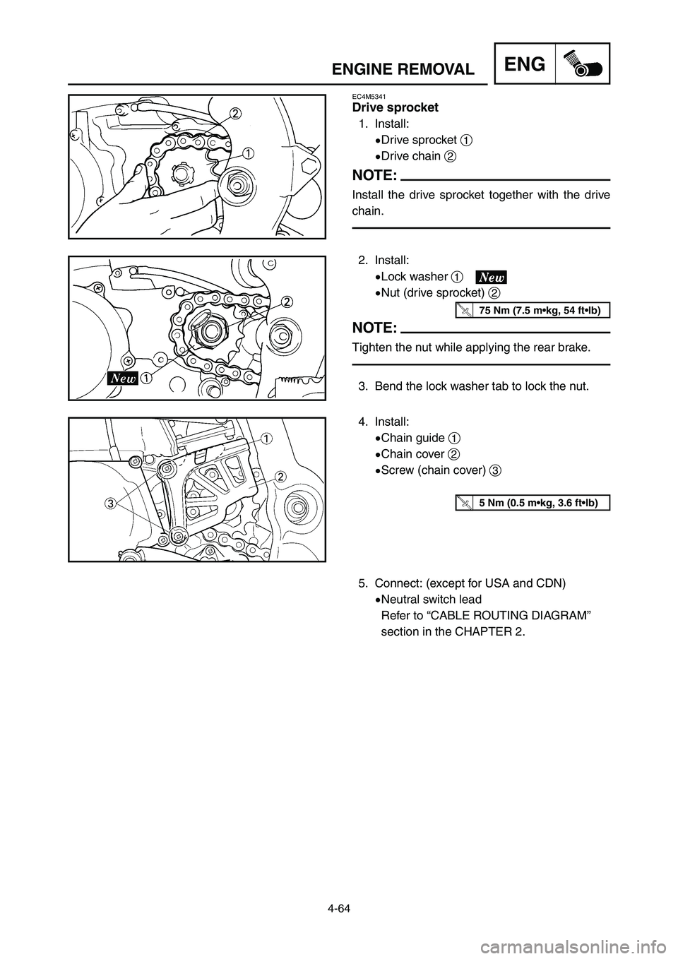
4. Install:
9Chain guide 1
9Chain cover 2
9Screw (chain cover) 3 2. Install:
9Lock washer 1
9Nut (drive sprocket) 2
NOTE:
Tighten the nut while applying the rear brake.
3. Bend the lock washer tab to lock the nut.
5 Nm (0.5 m•kg, 3.6 ft•lb)
75 Nm (7.5 m•kg, 54 ft•lb)
EC4M5341
Drive sprocket
1. Install:
9Drive sprocket 1
9Drive chain 2
NOTE:
Install the drive sprocket together with the drive
chain.
5. Connect: (except for USA and CDN)
9Neutral switch lead
Refer to “CABLE ROUTING DIAGRAM”
section in the CHAPTER 2.
1P8-9-32-4c 5/1/06 10:46 AM Page 30
Page 347 of 596
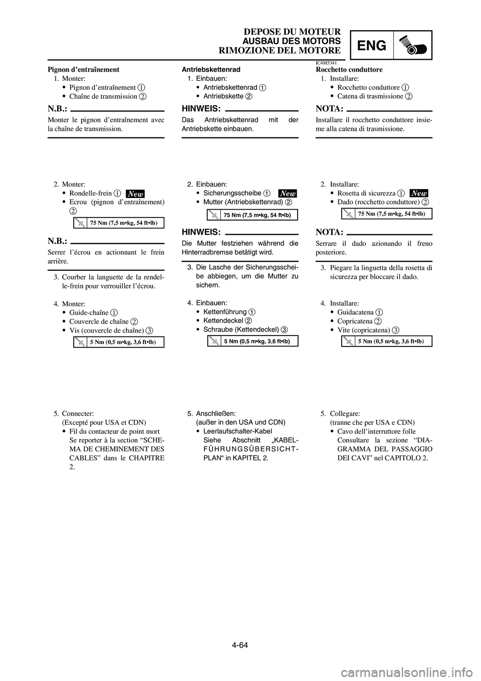
3. Die Lasche der Sicherungsschei-
be abbiegen, um die Mutter zu
sichern.
4. Einbauen:
9Kettenführung 1
9Kettendeckel 2
9Schraube (Kettendeckel) 3
3. Courber la languette de la rendel-
le-frein pour verrouiller l’écrou.
4. Monter:
9Guide-chaîne 1
9Couvercle de chaîne 2
9Vis (couvercle de chaîne) 33. Piegare la linguetta della rosetta di
sicurezza per bloccare il dado.
4. Installare:
9Guidacatena 1
9Copricatena 2
9Vite (copricatena) 3
4-64
DEPOSE DU MOTEUR
AUSBAU DES MOTORS
RIMOZIONE DEL MOTOREENG
2. Einbauen:
9Sicherungsscheibe 1
9Mutter (Antriebskettenrad) 2
HINWEIS:
Die Mutter festziehen während die
Hinterradbremse betätigt wird.
2. Monter:
9Rondelle-frein 1
9Ecrou (pignon d’entraînement)
2
N.B.:
Serrer l’écrou en actionnant le frein
arrière.
2. Installare:
9Rosetta di sicurezza 1
9Dado (rocchetto conduttore) 2
NOTA:
Serrare il dado azionando il freno
posteriore.
75 Nm (7,5 m•kg, 54 ft•lb)75 Nm (7,5 m•kg, 54 ft•lb)75 Nm (7,5 m•kg, 54 ft•lb)
5 Nm (0,5 m•kg, 3,6 ft•lb)5 Nm (0,5 m•kg, 3,6 ft•lb)5 Nm (0,5 m•kg, 3,6 ft•lb)
Pignon d’entraînement
1. Monter:
9Pignon d’entraînement 1
9Chaîne de transmission 2
N.B.:
Monter le pignon d’entraînement avec
la chaîne de transmission.
Antriebskettenrad
1. Einbauen:
9Antriebskettenrad 1
9Antriebskette 2
HINWEIS:
Das Antriebskettenrad mit der
Antriebskette einbauen.
IC4M5341Rocchetto conduttore
1. Installare:
9Rocchetto conduttore 1
9Catena di trasmissione 2
NOTA:
Installare il rocchetto conduttore insie-
me alla catena di trasmissione.
5. Connecter:
(Excepté pour USA et CDN)
9Fil du contacteur de point mort
Se reporter à la section “SCHE-
MA DE CHEMINEMENT DES
CABLES” dans le CHAPITRE
2.5. Anschließen:
(außer in den USA und CDN)
9Leerlaufschalter-Kabel
Siehe Abschnitt „KABEL-
FÜHRUNGSÜBERSICHT-
PLAN“ in KAPITEL 2.5. Collegare:
(tranne che per USA e CDN)
9Cavo dell’interruttore folle
Consultare la sezione “DIA-
GRAMMA DEL PASSAGGIO
DEI CAVI” nel CAPITOLO 2.
1P8-9-32-4c 5/1/06 10:46 AM Page 31
Page 348 of 596
4-65
CRANKCASE AND CRANKSHAFTENG
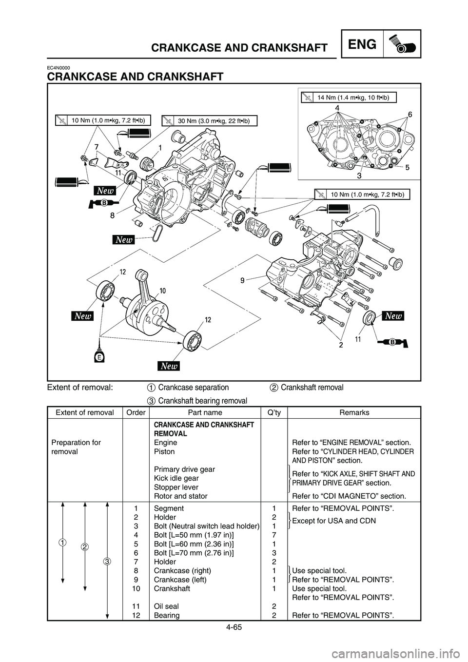
EC4N0000
CRANKCASE AND CRANKSHAFT
Extent of removal:1Crankcase separation2Crankshaft removal
3Crankshaft bearing removal
10 Nm (1.0 m•kg, 7.2 ft•lb)30 Nm (3.0 m•kg, 22 ft•lb)
14 Nm (1.4 m•kg, 10 ft•lb)
10 Nm (1.0 m•kg, 7.2 ft•lb)
Extent of removal Order Part name Q’ty Remarks
CRANKCASE AND CRANKSHAFT
REMOVAL
Preparation for Engine Refer to “ENGINE REMOVAL”section.
removal Piston Refer to “
CYLINDER HEAD, CYLINDER
AND PISTON
” section.
Primary drive gear
Kick idle gearRefer to “
KICK AXLE, SHIFT SHAFT AND
Stopper leverPRIMARY DRIVE GEAR”section.
Rotor and stator Refer to “CDI MAGNETO” section.
1 Segment 1 Refer to “REMOVAL POINTS”.
2 Holder 2
Except for USA and CDN
3 Bolt (Neutral switch lead holder) 1
4 Bolt [L=50 mm (1.97 in)] 7
5 Bolt [L=60 mm (2.36 in)] 1
6 Bolt [L=70 mm (2.76 in)] 3
7 Holder 2
8 Crankcase (right) 1 Use special tool.
9 Crankcase (left) 1 Refer to “REMOVAL POINTS”.
10 Crankshaft 1 Use special tool.
Refer to “REMOVAL POINTS”.
11 Oil seal 2
12 Bearing 2 Refer to “REMOVAL POINTS”.
12
3
1P8-9-32-4c 5/1/06 10:46 AM Page 32
Page 349 of 596
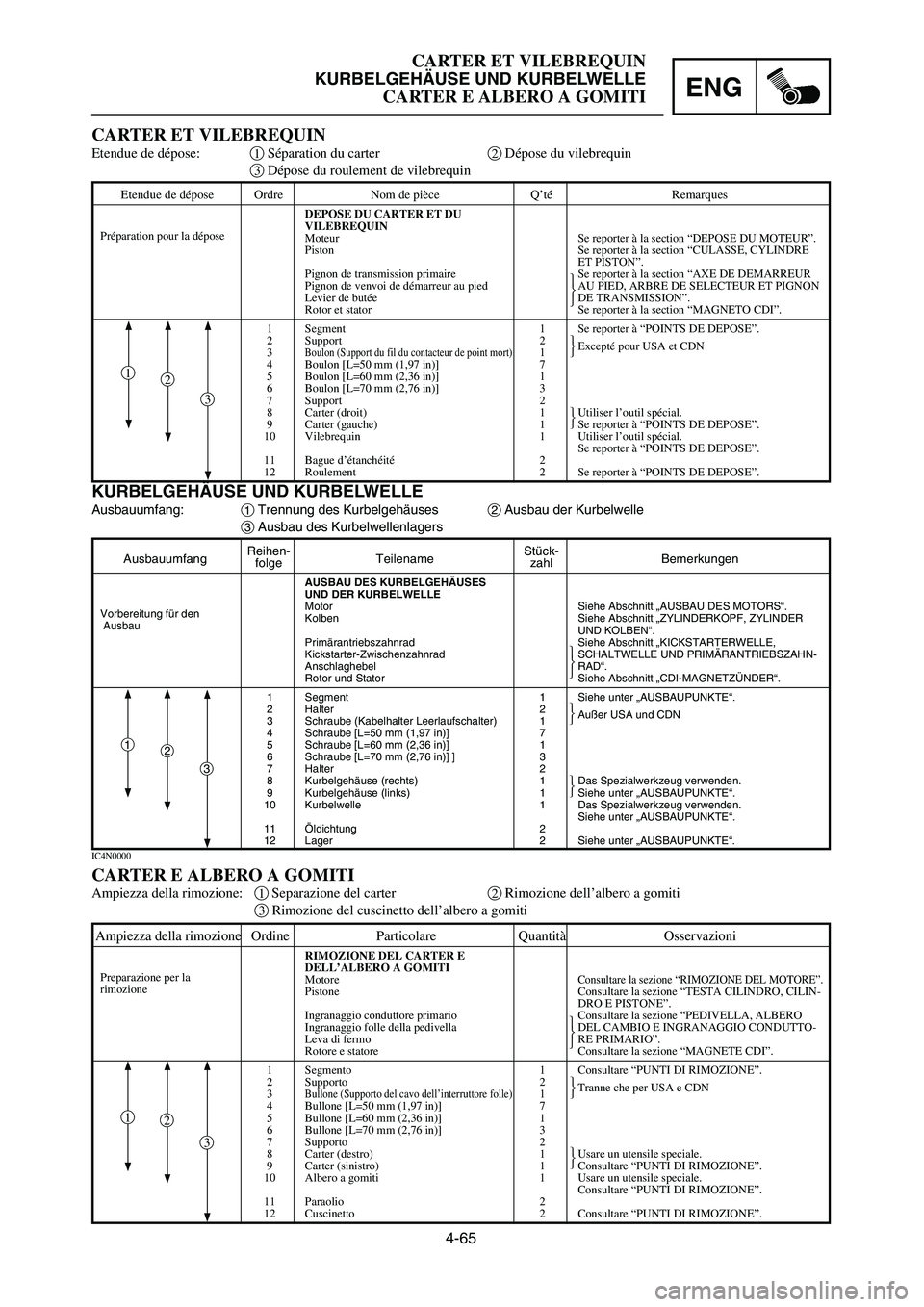
Etendue de dépose Ordre Nom de pièce Q’té Remarques
DEPOSE DU CARTER ET DU
VILEBREQUIN
Moteur Se reporter à la section “DEPOSE DU MOTEUR”.
Piston Se reporter à la section “CULASSE, CYLINDRE
ET PISTON”.
Pignon de transmission primaire Se reporter à la section “AXE DE DEMARREUR
Pignon de venvoi de démarreur au pied AU PIED, ARBRE DE SELECTEUR ET PIGNON
Levier de butée DE TRANSMISSION”.
Rotor et stator Se reporter à la section “MAGNETO CDI”.
1 Segment 1 Se reporter à “POINTS DE DEPOSE”.
2 Support 2
Excepté pour USA et CDN
3
Boulon (Support du fil du contacteur de point mort)1
4 Boulon [L=50 mm (1,97 in)] 7
5 Boulon [L=60 mm (2,36 in)] 1
6 Boulon [L=70 mm (2,76 in)] 3
7 Support 2
8 Carter (droit) 1 Utiliser l’outil spécial.
9 Carter (gauche) 1 Se reporter à “POINTS DE DEPOSE”.
10 Vilebrequin 1 Utiliser l’outil spécial.
Se reporter à “POINTS DE DEPOSE”.
11 Bague d’étanchéité 2
12 Roulement 2 Se reporter à “POINTS DE DEPOSE”.
4-65
CARTER ET VILEBREQUIN
KURBELGEHÄUSE UND KURBELWELLE
CARTER E ALBERO A GOMITIENG
AusbauumfangReihen-
TeilenameStück-
Bemerkungenfolge zahl
AUSBAU DES KURBELGEHÄUSES
UND DER KURBELWELLE
Motor Siehe Abschnitt „AUSBAU DES MOTORS“.
Kolben Siehe Abschnitt „ZYLINDERKOPF, ZYLINDER
UND KOLBEN“.
Primärantriebszahnrad Siehe Abschnitt „KICKSTARTERWELLE,
Kickstarter-Zwischenzahnrad SCHALTWELLE UND PRIMÄRANTRIEBSZAHN-
Anschlaghebel RAD“.
Rotor und Stator Siehe Abschnitt „CDI-MAGNETZÜNDER“.
1 Segment 1 Siehe unter „AUSBAUPUNKTE“.
2 Halter 2
Außer USA und CDN
3 Schraube (Kabelhalter Leerlaufschalter) 1
4 Schraube [L=50 mm (1,97 in)] 7
5 Schraube [L=60 mm (2,36 in)] 1
6 Schraube [L=70 mm (2,76 in)] ] 3
7 Halter 2
8 Kurbelgehäuse (rechts) 1 Das Spezialwerkzeug verwenden.
9 Kurbelgehäuse (links) 1 Siehe unter „AUSBAUPUNKTE“.
10 Kurbelwelle 1 Das Spezialwerkzeug verwenden.
Siehe unter „AUSBAUPUNKTE“.
11 Öldichtung 2
12 Lager 2 Siehe unter „AUSBAUPUNKTE“.
KURBELGEHÄUSE UND KURBELWELLE
Ausbauumfang:1Trennung des Kurbelgehäuses2Ausbau der Kurbelwelle
3Ausbau des Kurbelwellenlagers
CARTER ET VILEBREQUIN
Etendue de dépose:1Séparation du carter2Dépose du vilebrequin
3Dépose du roulement de vilebrequin
IC4N0000
CARTER E ALBERO A GOMITI
Ampiezza della rimozione:1Separazione del carter2Rimozione dell’albero a gomiti
3Rimozione del cuscinetto dell’albero a gomiti
Vorbereitung für den
Ausbau
Préparation pour la dépose
2
3
1
2
3
1
Ampiezza della rimozione Ordine Particolare Quantità Osservazioni
RIMOZIONE DEL CARTER E
DELL’ALBERO A GOMITI
Motore
Consultare la sezione “RIMOZIONE DEL MOTORE”.Pistone Consultare la sezione “TESTA CILINDRO, CILIN-
DRO E PISTONE”.
Ingranaggio conduttore primario Consultare la sezione “PEDIVELLA, ALBERO
Ingranaggio folle della pedivella DEL CAMBIO E INGRANAGGIO CONDUTTO-
Leva di fermo RE PRIMARIO”.
Rotore e statore Consultare la sezione “MAGNETE CDI”.
1 Segmento 1 Consultare “PUNTI DI RIMOZIONE”.
2 Supporto 2
Tranne che per USA e CDN
3
Bullone (Supporto del cavo dell’interruttore folle)1
4 Bullone [L=50 mm (1,97 in)] 7
5 Bullone [L=60 mm (2,36 in)] 1
6 Bullone [L=70 mm (2,76 in)] 3
7 Supporto 2
8 Carter (destro) 1 Usare un utensile speciale.
9 Carter (sinistro) 1 Consultare “PUNTI DI RIMOZIONE”.
10 Albero a gomiti 1 Usare un utensile speciale.
Consultare “PUNTI DI RIMOZIONE”.
11 Paraolio 2
12 Cuscinetto 2 Consultare “PUNTI DI RIMOZIONE”.
Preparazione per la
rimozione
2
3
1
1P8-9-32-4c 5/1/06 10:46 AM Page 33
Page 350 of 596
4-66
CRANKCASE AND CRANKSHAFTENG
EC4N3212
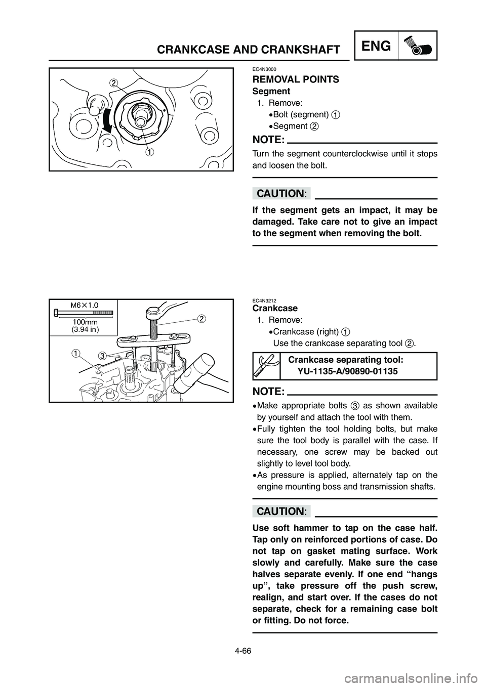
Crankcase
1. Remove:
9Crankcase (right) 1
Use the crankcase separating tool 2.
NOTE:
9Make appropriate bolts 3as shown available
by yourself and attach the tool with them.
9Fully tighten the tool holding bolts, but make
sure the tool body is parallel with the case. If
necessary, one screw may be backed out
slightly to level tool body.
9As pressure is applied, alternately tap on the
engine mounting boss and transmission shafts.
cC
Use soft hammer to tap on the case half.
Tap only on reinforced portions of case. Do
not tap on gasket mating surface. Work
slowly and carefully. Make sure the case
halves separate evenly. If one end “hangs
up”, take pressure off the push screw,
realign, and start over. If the cases do not
separate, check for a remaining case bolt
or fitting. Do not force.
EC4N3000
REMOVAL POINTS
Segment
1. Remove:
9Bolt (segment) 1
9Segment 2
NOTE:
Turn the segment counterclockwise until it stops
and loosen the bolt.
cC
If the segment gets an impact, it may be
damaged. Take care not to give an impact
to the segment when removing the bolt.
Crankcase separating tool:
YU-1135-A/90890-01135
1P8-9-32-4c 5/1/06 10:46 AM Page 34