fuel pump YAMAHA YZ426F 2000 Betriebsanleitungen (in German)
[x] Cancel search | Manufacturer: YAMAHA, Model Year: 2000, Model line: YZ426F, Model: YAMAHA YZ426F 2000Pages: 608, PDF-Größe: 45.52 MB
Page 22 of 608

CHAPTER 4
ENGINE
SEAT, FUEL TANK AND
SIDE COVERS
.......................................... 4-1
EXHAUST PIPE AND SILENCER
............ 4-3
RADIATOR
................................................ 4-4
CARBURETOR
......................................... 4-7
CAMSHAFTS
.......................................... 4-17
CYLINDER HEAD
................................... 4-24
VALVES AND VALVE SPRINGS
........... 4-27
CYLINDER AND PISTON
....................... 4-35
CLUTCH
.................................................. 4-41
OIL FILTER, WATER PUMP AND
CRANKCASE COVER (RIGHT)
............. 4-47
BALANCER
............................................ 4-53
OIL PUMP
............................................... 4-56
KICK AXLE AND SHIFT SHAFT
............ 4-60
CDI MAGNETO
....................................... 4-67
ENGINE REMOVAL
................................ 4-71
CRANKCASE AND CRANKSHAFT
....... 4-76
TRANSMISSION, SHIFT CAM,
SHIFT FORK
........................................... 4-85
CHAPTER 5
CHASSIS
FRONT WHEEL AND REAR WHEEL
...... 5-1
FRONT BRAKE AND REAR BRAKE
..... 5-10
FRONT FORK
......................................... 5-27
HANDLEBAR
.......................................... 5-40
STEERING
.............................................. 5-45
SWINGARM
............................................ 5-50
REAR SHOCK ABSORBER
................... 5- 57
Page 54 of 608

1 - 13
GEN
INFO
STARTING AND BREAK-IN
EC190000
STARTING AND BREAK-IN
WARNING
Never start or run the engine in a closed
area. The exhaust fumes are poisonous;
they can cause loss of consciousness and
death in a very short time. Always operate
the machine in a well-ventilated area.
CAUTION:
lThe carburetor on this motorcycle has a
built-in accelerator pump. Therefore,
when starting the engine, do not operate
the throttle or the spark plug will foul.
lUnlike a two-stroke engine, this engine
cannot be kick started when the throttle is
open because the kick starter may kick
back. Also, if the throttle is open the air/
fuel mixture may be too lean for the
engine to start.
lNever use the decompression lever after
the engine is started. The engine may be
damaged if you use the decompression
lever while it is running.
lBefore starting the machine, perform the
checks in the pre-operation check list.
EC191001
STARTING A COLD ENGINE
1. Inspect the coolant level.
2. Turn the fuel cock to “ON”.
3. Shift the transmission into neutral.
4. Fully open the cold starter knob.
5. Without pulling in the decompression
lever, slowly depress the kick starter until
the compression stroke is found. When
considerable resistance of the kick starter
is felt, the engine is on the compression
stroke. If the engine is on the exhaust
stroke, resistance will only be felt when
the kick starter is initially depressed, not
through the entire range of depression
(as when the engine is on the compres-
sion stroke); therefore, depress the kick
starter a few more times.
Page 56 of 608

1 - 14
GEN
INFO
STARTING AND BREAK-IN
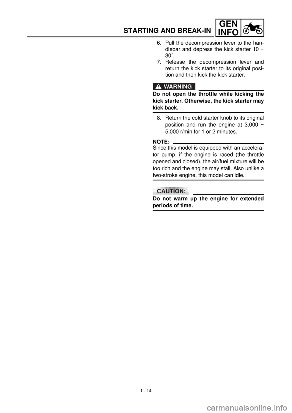
6. Pull the decompression lever to the han-
dlebar and depress the kick starter 10 ~
30˚.
7. Release the decompression lever and
return the kick starter to its original posi-
tion and then kick the kick starter.
WARNING
Do not open the throttle while kicking the
kick starter. Otherwise, the kick starter may
kick back.
8. Return the cold starter knob to its original
position and run the engine at 3,000 ~
5,000 r/min for 1 or 2 minutes.
NOTE:
Since this model is equipped with an accelera-
tor pump, if the engine is raced (the throttle
opened and closed), the air/fuel mixture will be
too rich and the engine may stall. Also unlike a
two-stroke engine, this model can idle.
CAUTION:
Do not warm up the engine for extended
periods of time.
Page 139 of 608

3 - 2
INSP
ADJ
MAINTENANCE INTERVALS
SHIFT FORK, SHIFT CAM, GUIDE BAR
Inspect
c
Inspect wear
ROTOR NUT
Retighten
cc
MUFFLER
Inspect
Clean
Replace
cc
cc
* Whichever comes first
CRANK
Inspect and clean
cc
CARBURETOR
Inspect, adjust and clean
cc
When using a high-pres-
sure washer, make sure
that water does not enter
the accelerator pump.
SPARK PLUG
Inspect and clean
Replace
cc
c
DRIVE CHAIN
Lubricate, slack, alignment
Replace
cc
c
Use chain lube
Chain slack: 40~50 mm
(1.6~2.0 in)
COOLING SYSTEM
Check coolant level and leakage
Check radiator cap operation
Replace coolant
Inspect hoses
cc
cc
c
Every two years
OUTSIDE NUTS AND BOLTS
Retighten
cc
Refer to “STARTING AND
BREAK-IN” section in the
CHAPTER 1.
AIR FILTER
Clean and lubricate
Replace
cc
c
Use foam air-filter oil
OIL STRAINER (frame)
Clean
c
FRAME
Clean and inspect
cc
FUEL TANK, COCK
Clean and inspect
cc
BRAKES
Adjust lever position and pedal height
Lubricate pivot point
Check brake disc surface
Check fluid level and leakage
Retighten brake disc bolts, caliper
bolts, master cylinder bolts and union
bolts
Replace pads
Replace brake fluid
c
c
c
c
cc
c
c
c
c
c
c
Every one year
FRONT FORKS
Inspect and adjust
Replace oil
Replace oil seal
c
cc
c
c
Suspension oil “01” ItemAfter
break-inEvery
race
Every
third
(or
500 km)Every
fifth
(or
1,000 km)
As re-
quiredRemarks
3
Page 174 of 608

3 - 17
INSP
ADJ
PILOT SCREW ADJUSTMENT
12. Check:
lOil pressure
Checking steps:
lSlightly loosen the oil gallery bolt 1.
lStart the engine and keep it idling until oil
starts to seep from the oil gallery bolt. If no
oil comes out after one minute, turn the
engine off so it will not seize.
lCheck oil passages, oil filter and oil pump
for damage or leakage.
lStart the engine after solving the prob-
lem(s) and recheck the oil pressure.
lTighten the oil gallery bolt to specification.
T R..
Oil gallery bolt:
18 Nm (1.8 m • kg, 13 ft • lb)
PILOT SCREW ADJUSTMENT
1. Adjust:
lPilot screw 1
* Except for USAAdjusting steps:
lTurn in the pilot screw until it is lightly
seated.
lTurn out the pilot screw by the factory-set
number of turns.
Pilot screw:
1-3/4 turns out
* 1-1/2 turns out
(for reference only)
NOTE:
To optimize the fuel flow at a smaller throt-
tle opening, each machine’s pilot screw has
been individually set at the factory. Before
adjusting the pilot screw, turn it in fully and
count the number of turns. Record this
number as the factory-set number of turns
out.
Page 562 of 608

7 - 1
TUN
EC700000
TUNING
EC710000
ENGINE
Carburetor setting
l
The air/fuel mixture will vary depending on
atmospheric conditions. Therefore, it is nec-
essary to take into consideration the air pres-
sure, ambient temperature, humidity, etc.,
when adjusting the carburetor.
l
Perform a test run to check for proper engine
performance (e.g., throttle response) and
spark plug(-s) discoloration or fouling. Use
these readings to determine the best possi-
ble carburetor setting.
NOTE:
It is recommended to keep a record of all car-
buretor settings and external conditions (e.g.,
atmospheric conditions, track/surface condi-
tions, lap times) to make future carburetor set-
ting easier.
WARNING
l
The carburetor is a part of the fuel line.
Therefore, be sure to install it in a well-
ventilated area, away from flammable
objects and any sources of fire.
l
Never look into the carburetor intake.
Flames may shoot out from the pipe if the
engine backfires while it is being started.
Gasoline may be discharged from the
accelerator pump nozzle when the carbu-
retor has been removed.
CAUTION:
l
The carburetor is extremely sensitive to
foreign matter (dirt, sand, water, etc.).
During installation, do not allow foreign
matter to get into the carburetor.
l
Always handle the carburetor and its com-
ponents carefully. Even slight scratches,
bends or damage to carburetor parts may
prevent the carburetor from functioning
correctly. Carefully perform all servicing
with the appropriate tools and without
applying excessive force.
l
When the engine is stopped or when
riding at no load, do not open and close
the throttle unnecessarily. Otherwise, too
much fuel may be discharged, starting
may become difficult or the engine may
not run well.
SETTING
7
Page 578 of 608

7 - 9
TUN
EC71D021
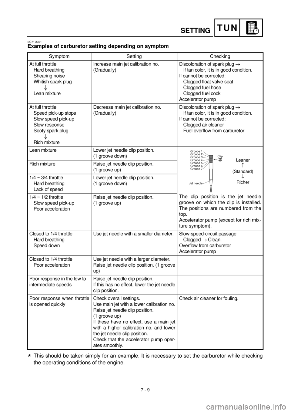
Examples of carburetor setting depending on symptom
This should be taken simply for an example. It is necessary to set the carburetor while checking
the operating conditions of the engine.
Symptom Setting Checking
At full throttle
Hard breathing
Shearing noise
Whitish spark plug
Lean mixtureIncrease main jet calibration no.
(Gradually)Discoloration of spark plug ®
If tan color, it is in good condition.
If cannot be corrected:
Clogged float valve seat
Clogged fuel hose
Clogged fuel cock
Accelerator pump
At full throttle
Speed pick-up stops
Slow speed pick-up
Slow response
Sooty spark plug
Rich mixtureDecrease main jet calibration no.
(Gradually)Discoloration of spark plug ®
If tan color, it is in good condition.
If cannot be corrected:
Clogged air cleaner
Fuel overflow from carburetor
Lean mixture Lower jet needle clip position.
(1 groove down)
The clip position is the jet needle
groove on which the clip is installed.
The positions are numbered from the
top.
Accelerator pump (except for rich mix-
ture symptom). Rich mixture Raise jet needle clip position.
(1 groove up)
1/4 ~ 3/4 throttle
Hard breathing
Lack of speedLower jet needle clip position.
(1 groove down)
1/4 ~ 1/2 throttle
Slow speed pick-up
Poor accelerationRaise jet needle clip position.
(1 groove up)
Closed to 1/4 throttle
Hard breathing
Speed downUse jet needle with a smaller diameter. Slow-speed-circuit passage
Clogged ® Clean.
Overflow from carburetor
Accelerator pump
Closed to 1/4 throttle
Poor accelerationUse jet needle with a larger diameter.
Raise jet needle clip position. (1 groove
up)
Poor response in the low to
intermediate speedsRaise jet needle clip position.
If this has no effect, lower the jet needle
clip position.
Poor response when throttle
is opened quicklyCheck overall settings.
Use main jet with a lower calibration no.
Raise jet needle clip position.
(1 groove up)
If these have no effect, use a main jet
with a higher calibration no. and lower
the jet needle clip position.
Check that the accelerator pump oper-
ates smoothly.Check air cleaner for fouling.
Jet needleClip
Groobe 7 Groobe 6
Groobe 5
Groobe 4
Groobe 3
Groobe 2
Groobe 1
Leaner
(Standard)
¯
Richer
*
SETTING