YAMAHA YZ426F 2000 Owners Manual
Manufacturer: YAMAHA, Model Year: 2000, Model line: YZ426F, Model: YAMAHA YZ426F 2000Pages: 608, PDF Size: 45.52 MB
Page 271 of 608
ENG
4 - 18
ARBRE A CAMES
NOCKENWELLE
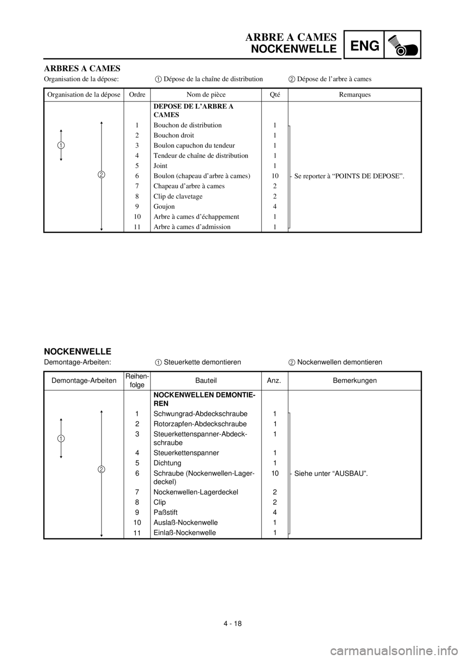
NOCKENWELLE
Demontage-Arbeiten:1 Steuerkette demontieren2 Nockenwellen demontieren
Demontage-ArbeitenReihen-
folgeBauteil Anz. Bemerkungen
NOCKENWELLEN DEMONTIE-
REN
1 Schwungrad-Abdeckschraube 1
Siehe unter “AUSBAU”. 2 Rotorzapfen-Abdeckschraube 1
3 Steuerkettenspanner-Abdeck-
schraube1
4 Steuerkettenspanner 1
5 Dichtung 1
6 Schraube (Nockenwellen-Lager-
deckel)10
7 Nockenwellen-Lagerdeckel 2
8 Clip 2
9 Paßstift 4
10 Auslaß-Nockenwelle 1
11Einlaß-Nockenwelle 1
2
1
ARBRES A CAMES
Organisation de la dépose:1 Dépose de la chaîne de distribution2 Dépose de l’arbre à cames
Organisation de la dépose Ordre Nom de pièce Qté Remarques
DEPOSE DE L’ARBRE A
CAMES
1 Bouchon de distribution 1
Se reporter à “POINTS DE DEPOSE”. 2 Bouchon droit 1
3 Boulon capuchon du tendeur 1
4 Tendeur de chaîne de distribution 1
5 Joint 1
6 Boulon (chapeau d’arbre à cames) 10
7 Chapeau d’arbre à cames 2
8 Clip de clavetage 2
9 Goujon 4
10 Arbre à cames d’échappement 1
11Arbre à cames d’admission
1
2
1
Page 272 of 608
4 - 19
ENGCAMSHAFTS
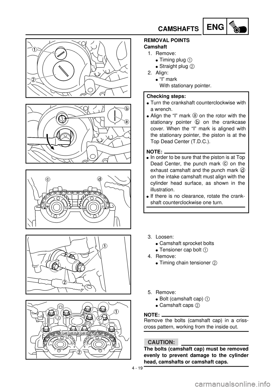
REMOVAL POINTS
Camshaft
1. Remove:
lTiming plug 1
lStraight plug 2
2. Align:
l“I” mark
With stationary pointer.
Checking steps:
lTurn the crankshaft counterclockwise with
a wrench.
lAlign the “I” mark a on the rotor with the
stationary pointer b on the crankcase
cover. When the “I” mark is aligned with
the stationary pointer, the piston is at the
Top Dead Center (T.D.C.).
NOTE:
lIn order to be sure that the piston is at Top
Dead Center, the punch mark c on the
exhaust camshaft and the punch mark d
on the intake camshaft must align with the
cylinder head surface, as shown in the
illustration.
lIf there is no clearance, rotate the crank-
shaft counterclockwise one turn.
3. Loosen:
lCamshaft sprocket bolts
lTensioner cap bolt 1
4. Remove:
lTiming chain tensioner 2
5. Remove:
lBolt (camshaft cap) 1
lCamshaft caps 2
NOTE:
Remove the bolts (camshaft cap) in a criss-
cross pattern, working from the inside out.
CAUTION:
The bolts (camshaft cap) must be removed
evenly to prevent damage to the cylinder
head, camshafts or camshaft caps.
Page 273 of 608
4 - 19
ENG
ARBRE A CAMES
NOCKENWELLE
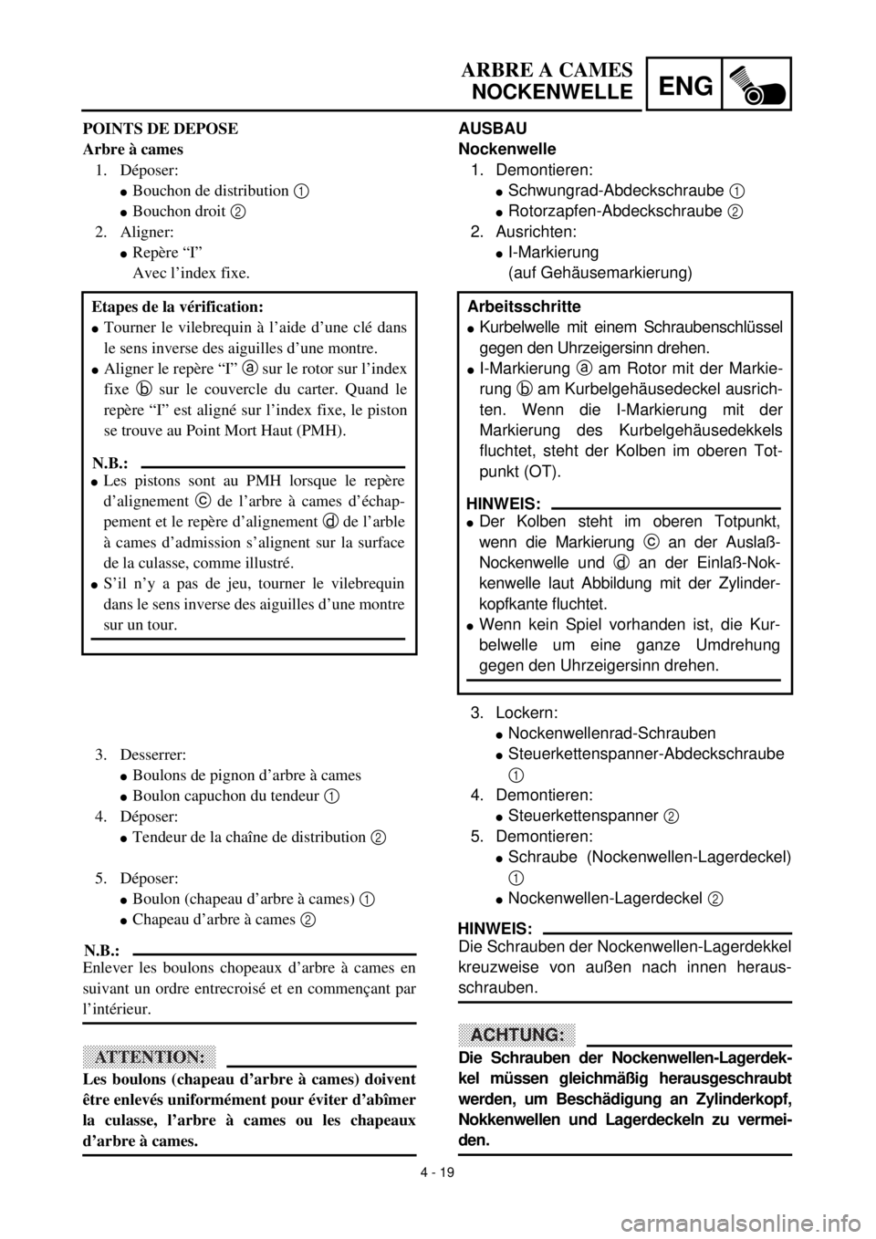
AUSBAU
Nockenwelle
1. Demontieren:
lSchwungrad-Abdeckschraube 1
lRotorzapfen-Abdeckschraube 2
2. Ausrichten:
lI-Markierung
(auf Gehäusemarkierung)
3. Lockern:
lNockenwellenrad-Schrauben
lSteuerkettenspanner-Abdeckschraube
1
4. Demontieren:
lSteuerkettenspanner 2
5. Demontieren:
lSchraube (Nockenwellen-Lagerdeckel)
1
lNockenwellen-Lagerdeckel 2
HINWEIS:
Die Schrauben der Nockenwellen-Lagerdekkel
kreuzweise von außen nach innen heraus-
schrauben.
ACHTUNG:
Die Schrauben der Nockenwellen-Lagerdek-
kel müssen gleichmäßig herausgeschraubt
werden, um Beschädigung an Zylinderkopf,
Nokkenwellen und Lagerdeckeln zu vermei-
den.Arbeitsschritte
lKurbelwelle mit einem Schraubenschlüssel
gegen den Uhrzeigersinn drehen.
lI-Markierung a am Rotor mit der Markie-
rung b am Kurbelgehäusedeckel ausrich-
ten. Wenn die I-Markierung mit der
Markierung des Kurbelgehäusedekkels
fluchtet, steht der Kolben im oberen Tot-
punkt (OT).
HINWEIS:
lDer Kolben steht im oberen Totpunkt,
wenn die Markierung c an der Auslaß-
Nockenwelle und d an der Einlaß-Nok-
kenwelle laut Abbildung mit der Zylinder-
kopfkante fluchtet.
lWenn kein Spiel vorhanden ist, die Kur-
belwelle um eine ganze Umdrehung
gegen den Uhrzeigersinn drehen. POINTS DE DEPOSE
Arbre à cames
1. Déposer:
lBouchon de distribution 1
lBouchon droit 2
2. Aligner:
lRepère “I”
Avec l’index fixe.
Etapes de la vérification:
lTourner le vilebrequin à l’aide d’une clé dans
le sens inverse des aiguilles d’une montre.
lAligner le repère “I” a sur le rotor sur l’index
fixe b sur le couvercle du carter. Quand le
repère “I” est aligné sur l’index fixe, le piston
se trouve au Point Mort Haut (PMH).
N.B.:
lLes pistons sont au PMH lorsque le repère
d’alignement c de l’arbre à cames d’échap-
pement et le repère d’alignement d de l’arble
à cames d’admission s’alignent sur la surface
de la culasse, comme illustré.
lS’il n’y a pas de jeu, tourner le vilebrequin
dans le sens inverse des aiguilles d’une montre
sur un tour.
3. Desserrer:
lBoulons de pignon d’arbre à cames
lBoulon capuchon du tendeur 1
4. Déposer:
lTendeur de la chaîne de distribution 2
5. Déposer:
lBoulon (chapeau d’arbre à cames) 1
lChapeau d’arbre à cames 2
N.B.:
Enlever les boulons chopeaux d’arbre à cames en
suivant un ordre entrecroisé et en commençant par
l’intérieur.
ATTENTION:
Les boulons (chapeau d’arbre à cames) doivent
être enlevés uniformément pour éviter d’abîmer
la culasse, l’arbre à cames ou les chapeaux
d’arbre à cames.
Page 274 of 608
4 - 20
ENGCAMSHAFTS
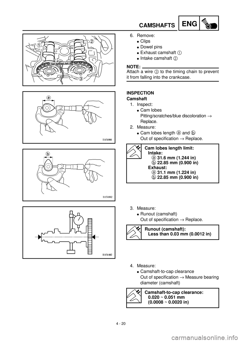
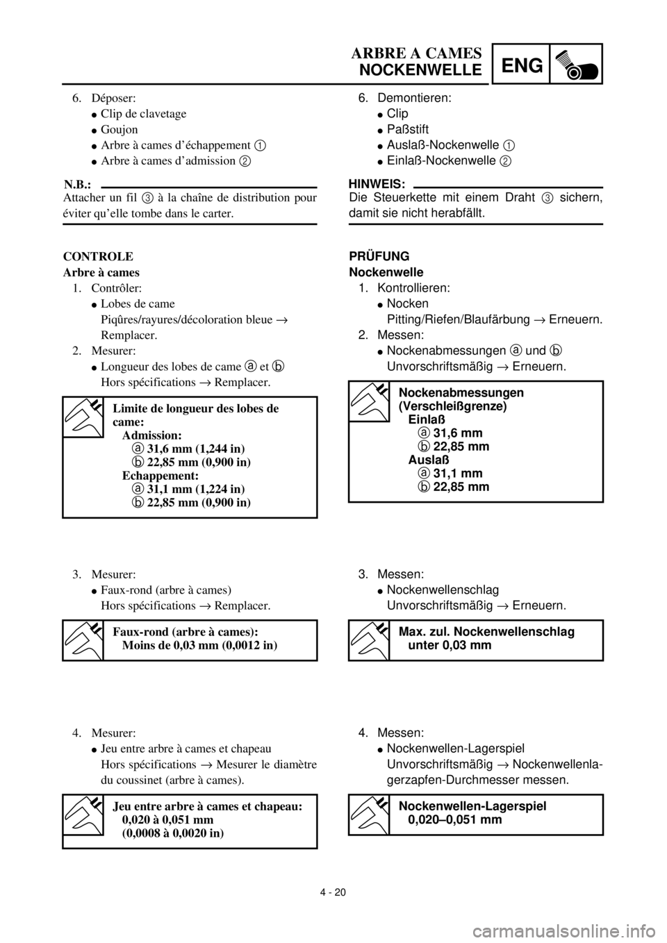
6. Remove:
lClips
lDowel pins
lExhaust camshaft 1
lIntake camshaft 2
NOTE:
Attach a wire 3 to the timing chain to prevent
it from falling into the crankcase.
INSPECTION
Camshaft
1. Inspect:
lCam lobes
Pitting/scratches/blue discoloration ®
Replace.
2. Measure:
lCam lobes length a and b
Out of specification ® Replace.
Cam lobes length limit:
Intake:
a 31.6 mm (1.244 in)
b 22.85 mm (0.900 in)
Exhaust:
a 31.1 mm (1.224 in)
b 22.85 mm (0.900 in)
3. Measure:
lRunout (camshaft)
Out of specification ® Replace.
Runout (camshaft):
Less than 0.03 mm (0.0012 in)
4. Measure:
lCamshaft-to-cap clearance
Out of specification ® Measure bearing
diameter (camshaft)
Camshaft-to-cap clearance:
0.020 ~ 0.051 mm
(0.0008 ~ 0.0020 in)
Page 275 of 608
4 - 20
ENG
ARBRE A CAMES
NOCKENWELLE
6. Demontieren:
lClip
lPaßstift
lAuslaß-Nockenwelle 1
lEinlaß-Nockenwelle 2
HINWEIS:
Die Steuerkette mit einem Draht 3 sichern,
damit sie nicht herabfällt.
PRÜFUNG
Nockenwelle
1. Kontrollieren:
lNocken
Pitting/Riefen/Blaufärbung ® Erneuern.
2. Messen:
lNockenabmessungen a und b
Unvorschriftsmäßig ® Erneuern.
Nockenabmessungen
(Verschleißgrenze)
Einlaß
a 31,6 mm
b 22,85 mm
Auslaß
a 31,1 mm
b 22,85 mm
3. Messen:
lNockenwellenschlag
Unvorschriftsmäßig ® Erneuern.
Max. zul. Nockenwellenschlag
unter 0,03 mm
4. Messen:
lNockenwellen-Lagerspiel
Unvorschriftsmäßig ® Nockenwellenla-
gerzapfen-Durchmesser messen.
Nockenwellen-Lagerspiel
0,020–0,051 mm
6. Déposer:
lClip de clavetage
lGoujon
lArbre à cames d’échappement 1
lArbre à cames d’admission 2
N.B.:
Attacher un fil 3 à la chaîne de distribution pour
éviter qu’elle tombe dans le carter.
CONTROLE
Arbre à cames
1. Contrôler:
lLobes de came
Piqûres/rayures/décoloration bleue ®
Remplacer.
2. Mesurer:
lLongueur des lobes de came a et b
Hors spécifications ® Remplacer.
Limite de longueur des lobes de
came:
Admission:
a 31,6 mm (1,244 in)
b 22,85 mm (0,900 in)
Echappement:
a 31,1 mm (1,224 in)
b 22,85 mm (0,900 in)
3. Mesurer:
lFaux-rond (arbre à cames)
Hors spécifications ® Remplacer.
Faux-rond (arbre à cames):
Moins de 0,03 mm (0,0012 in)
4. Mesurer:
lJeu entre arbre à cames et chapeau
Hors spécifications ® Mesurer le diamètre
du coussinet (arbre à cames).
Jeu entre arbre à cames et chapeau:
0,020 à 0,051 mm
(0,0008 à 0,0020 in)
Page 276 of 608
4 - 21
ENG
CAMSHAFTS
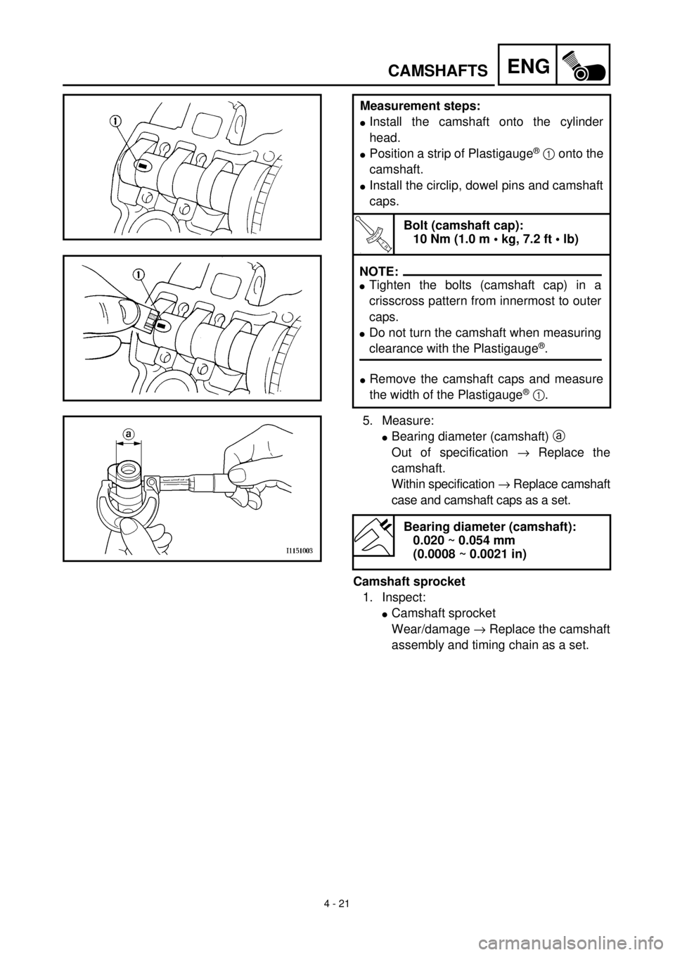
Measurement steps:
l
Install the camshaft onto the cylinder
head.
l
Position a strip of Plastigauge
®
1
onto the
camshaft.
l
Install the circlip, dowel pins and camshaft
caps.
T R..
Bolt (camshaft cap):
10 Nm (1.0 m • kg, 7.2 ft • lb)
.
l
Remove the camshaft caps and measure
the width of the Plastigauge
®
1
.
NOTE:
lTighten the bolts (camshaft cap) in a
crisscross pattern from innermost to outer
caps.
lDo not turn the camshaft when measuring
clearance with the Plastigauge®.
5. Measure:
l
Bearing diameter (camshaft)
a
Out of specification
®
Replace the
camshaft.
Within specification
®
Replace camshaft
case and camshaft caps as a set.
Bearing diameter (camshaft):
0.020 ~ 0.054 mm
(0.0008 ~ 0.0021 in)
Camshaft sprocket
1. Inspect:
l
Camshaft sprocket
Wear/damage
®
Replace the camshaft
assembly and timing chain as a set.
Page 277 of 608
4 - 21
ENG
ARBRE A CAMES
NOCKENWELLE
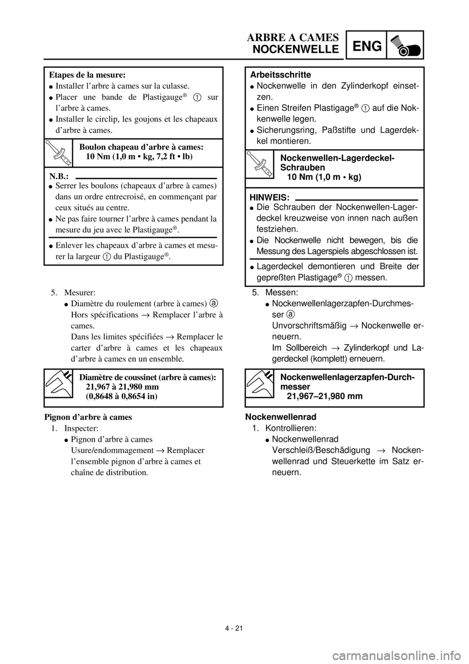
Arbeitsschritte
l
Nockenwelle in den Zylinderkopf einset-
zen.
l
Einen Streifen Plastigage
®
1
auf die Nok-
kenwelle legen.
l
Sicherungsring, Paßstifte und Lagerdek-
kel montieren.
T R..
Nockenwellen-Lagerdeckel-
Schrauben
10 Nm (1,0 m • kg)
.
l
Lagerdeckel demontieren und Breite der
gepreßten Plastigage
®
1
messen.
HINWEIS:
lDie Schrauben der Nockenwellen-Lager-
deckel kreuzweise von innen nach außen
festziehen.
lDie Nockenwelle nicht bewegen, bis die
Messung des Lagerspiels abgeschlossen ist.
5. Messen:
l
Nockenwellenlagerzapfen-Durchmes-
ser
a
Unvorschriftsmäßig
®
Nockenwelle er-
neuern.
Im Sollbereich
®
Zylinderkopf und La-
gerdeckel (komplett) erneuern.
Nockenwellenrad
1. Kontrollieren:
l
Nockenwellenrad
Verschleiß/Beschädigung
®
Nocken-
wellenrad und Steuerkette im Satz er-
neuern.
Nockenwellenlagerzapfen-Durch-
messer
21,967–21,980 mm
Etapes de la mesure:
l
Installer l’arbre à cames sur la culasse.
l
Placer une bande de Plastigauge
®
1
sur
l’arbre à cames.
l
Installer le circlip, les goujons et les chapeaux
d’arbre à cames.
T R..
Boulon chapeau d’arbre à cames:
10 Nm (1,0 m • kg, 7,2 ft • lb)
.
l
Enlever les chapeaux d’arbre à cames et mesu-
rer la largeur
1
du Plastigauge
®
.
N.B.:
lSerrer les boulons (chapeaux d’arbre à cames)
dans un ordre entrecroisé, en commençant par
ceux situés au centre.
lNe pas faire tourner l’arbre à cames pendant la
mesure du jeu avec le Plastigauge®.
5. Mesurer:
l
Diamètre du roulement (arbre à cames)
a
Hors spécifications
®
Remplacer l’arbre à
cames.
Dans les limites spécifiées
®
Remplacer le
carter d’arbre à cames et les chapeaux
d’arbre à cames en un ensemble.
Pignon d’arbre à cames
1. Inspecter:
l
Pignon d’arbre à cames
Usure/endommagement
®
Remplacer
l’ensemble pignon d’arbre à cames et
chaîne de distribution.
Diamètre de coussinet (arbre à cames):
21,967 à 21,980 mm
(0,8648 à 0,8654 in)
Page 278 of 608
4 - 22
ENG
CAMSHAFTS
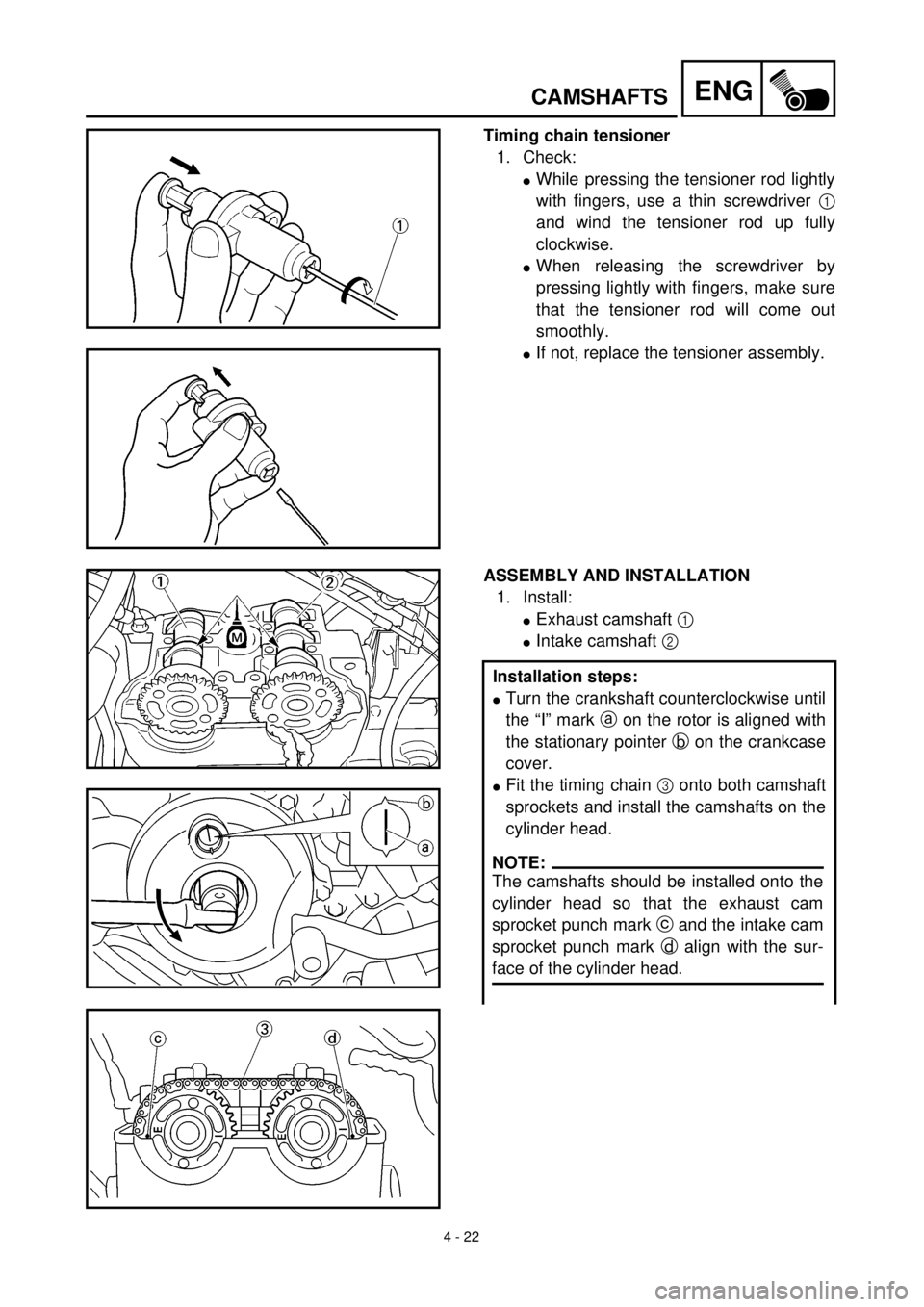
Timing chain tensioner
1. Check:
l
While pressing the tensioner rod lightly
with fingers, use a thin screwdriver
1
and wind the tensioner rod up fully
clockwise.
l
When releasing the screwdriver by
pressing lightly with fingers, make sure
that the tensioner rod will come out
smoothly.
l
If not, replace the tensioner assembly.
ASSEMBLY AND INSTALLATION
1. Install:
l
Exhaust camshaft
1
l
Intake camshaft
2
Installation steps:
l
Turn the crankshaft counterclockwise until
the “I” mark
a
on the rotor is aligned with
the stationary pointer
b
on the crankcase
cover.
l
Fit the timing chain
3
onto both camshaft
sprockets and install the camshafts on the
cylinder head.
NOTE:
The camshafts should be installed onto the
cylinder head so that the exhaust cam
sprocket punch mark c and the intake cam
sprocket punch mark d align with the sur-
face of the cylinder head.
Page 279 of 608
4 - 22
ENG
ARBRE A CAMES
NOCKENWELLE
Steuerkettenspanner
1. Kontrollieren:
l
Den Steuerkettenspannerkopf leicht mit
dem Finger eindrücken und den Span-
ner mit einem dünnen Schraubendre-
her
1
im Uhrzeigersinn aufdrehen.
l
Den Schraubendreher durch leichten
Fingerdruck auf dem Spannerkopf be-
freien; sicherstellen, daß sich der Span-
nerkopf dabei leichtgängig löst.
l
Anderenfalls den Steuerkettenspanner
(komplett) erneuern.
ZUSAMMENBAU UND MONTAGE
1. Montieren:
l
Auslaß-Nockenwelle
1
l
Einlaß-Nockenwelle
2
Arbeitsschritte
l
Kurbelwelle gegen den Uhrzeigersinn dre-
hen, bis die I-Markierung
a
am Rotor mit
der Markierung
b
des Kurbelgehäusedek-
kels fluchtet.
l
Die Steuerkette
3
auf beide Nockenwel-
lenräder legen und die Nockenwellen am
Zylinderkopf montieren.
HINWEIS:
Die Nockenwellen so auf den Zylinderkopf
setzen, daß die Stanzmarkierung c an der
Auslaß-Nockenwelle und d an der Einlaß-
Nockenwelle mit der Zylinderkopfkante
fluchtet.
Tendeur de la chaîne de distribution
1. Contrôler:
l
Tout en comprimant légèrement la tige du
tendeur à l’aide du doigt, la visser complè-
tement (tourner dans le sens des aiguilles
d’une montre) en se servant d’un tournevis
fin
1
.
l
Après avoir retiré le tournevis eh appuyant
légèrement du doigt, vérifier si la tige du
tendeur sort sans problème.
l
Si elle ne sort pas, remplacer le tendeur.
ASSEMBLAGE ET MONTAGE
1. Monter:
l
Arbre à cames d’échappement
1
l
Arbre à cames d’admission
2
Etapes de l’installation:
l
Tourner le vilebrequin dans le sens inverse des
aiguilles d’une montre pour aligner le repère
a
sur le rotor avec l’index fixe
b
du couver-
cle de carter.
l
Placer la chaîne de distribution
3
sur les deux
pignons d’arbre à cames et installer les arbres
à cames sur la culasse.
N.B.:
Monter les arbres à cames sur la culasse en
veillant à ce que les repères d’alignement c de
arbre à cames d’échappment et le repère d’ali-
gnement d de l’arbre à cames d’admission
s’alignent sur la surface de la culasse.
Page 280 of 608
4 - 23
ENG
CAMSHAFTS
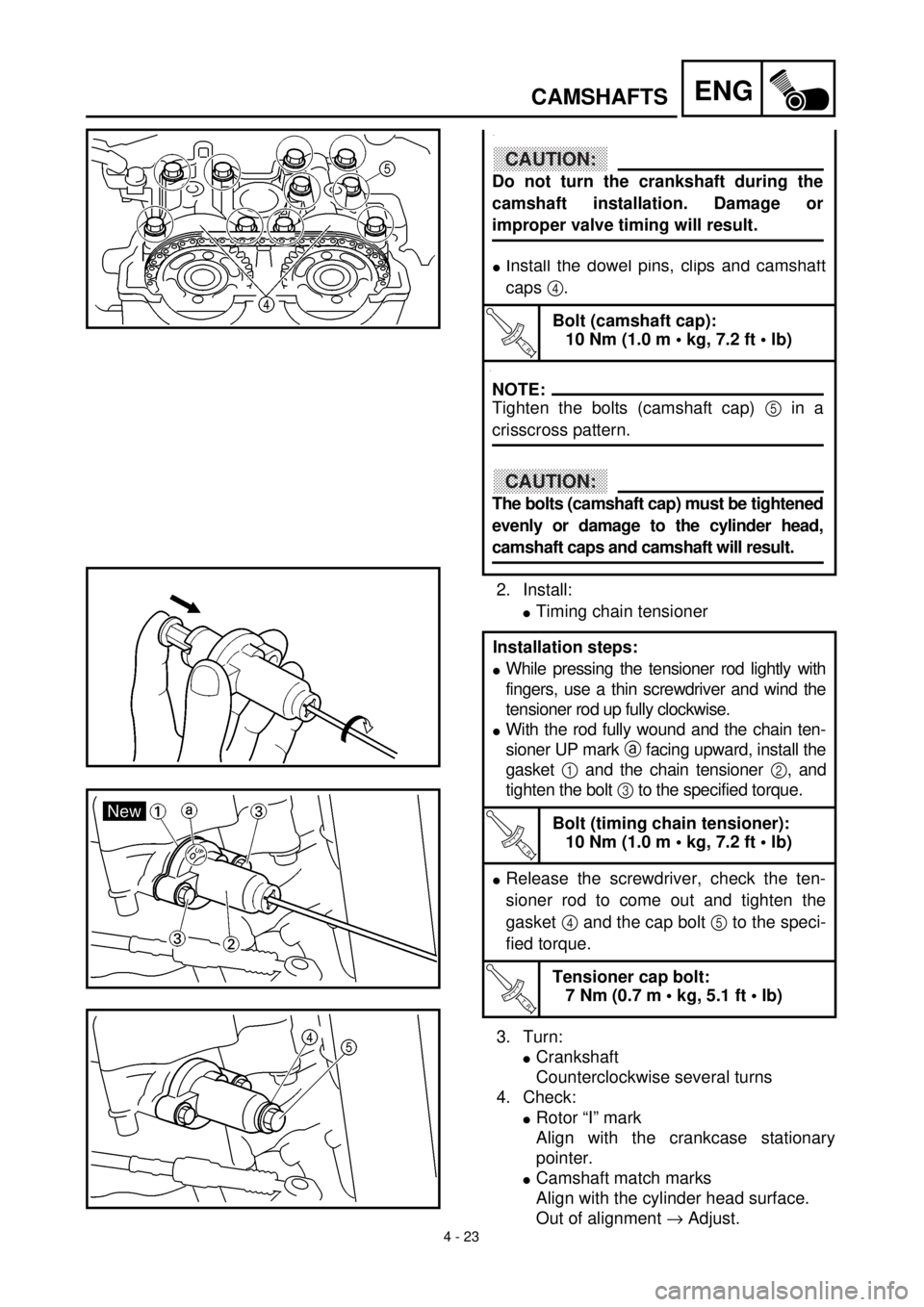
2. Install:
l
Timing chain tensioner
3. Turn:
l
Crankshaft
Counterclockwise several turns
4. Check:
l
Rotor “I” mark
Align with the crankcase stationary
pointer.
l
Camshaft match marks
Align with the cylinder head surface.
Out of alignment
®
Adjust.
.
l
Install the dowel pins, clips and camshaft
caps
4
.
T R..
Bolt (camshaft cap):
10 Nm (1.0 m • kg, 7.2 ft • lb)
.
Installation steps:
l
While pressing the tensioner rod lightly with
fingers, use a thin screwdriver and wind the
tensioner rod up fully clockwise.
l
With the rod fully wound and the chain ten-
sioner UP mark
a
facing upward, install the
gasket
1
and the chain tensioner
2
, and
tighten the bolt
3
to the specified torque.
T R..
Bolt (timing chain tensioner):
10 Nm (1.0 m • kg, 7.2 ft • lb)
l
Release the screwdriver, check the ten-
sioner rod to come out and tighten the
gasket
4
and the cap bolt
5
to the speci-
fied torque.
T R..
Tensioner cap bolt:
7 Nm (0.7 m • kg, 5.1 ft • lb)
CAUTION:
Do not turn the crankshaft during the
camshaft installation. Damage or
improper valve timing will result.
NOTE:
Tighten the bolts (camshaft cap) 5 in a
crisscross pattern.
CAUTION:
The bolts (camshaft cap) must be tightened
evenly or damage to the cylinder head,
camshaft caps and camshaft will result.